1
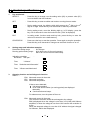
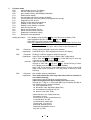
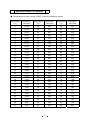
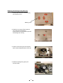
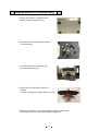
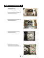
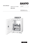
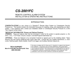
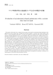
Service Manual
Shaker
MIR-S100
MIR-S100
Effective model
This service manual is effective following model.
Model name
MIR-S100
㩷
Model code
823 285 51
823 285 56
Voltage and Frequency
115V
60Hz
110V
60Hz
Contents
Page
Features ................................................................................................................ 1
Specifications ........................................................................................................ 2
Dimensions............................................................................................................ 3
Electrical parts....................................................................................................... 4
Wiring diagram ...................................................................................................... 6
Circuit diagram ...................................................................................................... 7
Components on PCB............................................................................................. 8
Connections on PCB ............................................................................................. 9
Control specifications .......................................................................................... 10
Specifications of Sensor...................................................................................... 18
Parts layout ......................................................................................................... 19
Replacement of the bearing ................................................................................ 20
Replacement of the base ass’y ........................................................................... 24
Replacement of the belt ...................................................................................... 25
Instruction Manual ............................................................................................... 27
Features
䂓㩷 The revolution is settable in variable speed, 50rpm~500rpm.
䂓㩷 Auto limit function is installed to make less vibration.
䂓㩷 MIR-S100 is the thin type shaker and it has the low center of gravity to realize less
vibration and less noise.
䂓㩷 MIR-S100 can combine with incubator (MIR-153 and MIR-253 and MIR-553) and
versatile test chamber (MLR-350).
The indication on the control panel can be checked with the window of the incubator
because the control panel is located in the center of the shaker.
䂓㩷 The stainless steel exterior makes cleaning easier.
1
㩷
Specifications
㩷
㩷
ŶStructural specifications
Name
Model
External dimensions
Exterior
Platform dimensions
Platform
Shaking motion
Amplitude
(Shaking diameter)
Revolution
Allowable load weight
Flask intake capacity
Display
Motor
Accessories
Power source
Weight
Optional component
Shaker
MIR-S100
W410 × D305 × H120 mm
Body: Painted steel
Cover: Stainless steel
W380 × D250 mm
Stainless steel containing copper
Circling
20 mm
50~500 rpm
5 kg
MIR-38PFT: 100ml Erlenmeyer Flask x 15, 500ml Erlenmeyer Flask x 5
MIR-38PFN: 100ml Erlenmeyer Flask x 15, 500ml Erlenmeyer Flask x 6
3-digit LED (speeds/time changeable)
Brushless DC motor (3-phase)
Power supply cord
100-240V, 50/60Hz
15 kg
DAQ communication kit MTR-480, MTR-2000
Platform (MIR-38PFT, MIR-38PFN), Clamp(MIR-51FC, MIR-101FC,
MIR-201FC, MIR-301FC, MIR-501FC, MIR-1001FC, MIR-2001FC)
Test tube rack (MIR-204SC)
㩷
㩷
㩷
㩷
㩷
㩷
㩷
㩷
㩷
㩷
㩷
㩷
㩷
㩷
㩷
㩷
㩷
2
㩷
ŶFunctions
Auto limit
Rotational acceleration
Timer
Total running time
Key lock
Auto start after power
failure
Revolution abnormality
Motor overload protection
circuit
Over-current breaker
Motor protection
Maintenance notice
Failure predicting
Reduces the revolution speed when it detects abnormal vibration during
shaker running.
AUTO LIMIT lamp is lit when Autolimit mode is activated.
At the start-up, accelerate the rotational speed slowly to prevent the
culture bubbling or spitting from the flask.
䋨acceleration speeds has 3steps, 1, 2, 3䋩
Changeable 0.0~99.9 hours, timer counts up 6minutes increment in more than
6 minutes indication.
䋨Counts up/down 1seconds increment/decrement in equal or less than 5
minutes and 59seconds䋩
Total running time can be checked in function mode.
The key in the control panel is not able to operate by.
Restarts operation after power failure. “PF” and revolution are alternately
displayed.
“E07” flashes when revolution doesn’t arrive setting speed or over
setting speed.
Stops automatically the operation when the motor is overloaded and the
over-current is detected. “E06” flashes.
The power switch serves as breaker
When the internal temperature goes higher abnormally, the unit stops
operation with the alarm occurred.
When the total running time is reached in 10,000hours, “CH1” flashes
twice after the power turns on.
Arrival time up to 100rpm (up to the setting rpm in the case of rpm less
than 100rpm) is 90 seconds or more, “CH2” flashes twice and the
diagnosis should be done that mechanical components are abnormal.
ŶPerformance
Usable environment condition
Maximum power consumption
Maximum total current
Maximum heat emission
Temperature: 0~60㷄㩷 Humidity: equal or less than 80%R.H.
27 W
0.27 A
97 KJ/h
* These data based on our measuring method.
㩷㩷
3
Dimensions
4
㩷
Electrical parts
㩷
㩷
Part name
Specifications
Type: ZUG2210-11
Noise filter
Rating: 10A
Power supply cord
Rating: AC125V, 12A
Motor
Type: FY8S25H-D3
Type: BAM205171
Power switch
Rating: AC250V, 5A
Type: ZWS50AF-24/J
Switching power supply
Rating:AC24V, 50W
Type: 103AT-1
Temp. sensor
Rating: 10K㱅, 25㷄
㩷
5
Wiring diagram
6
Circuit diagram
7
Components on PCB
8
Connections on PCB
Following shows the connections on the PCB.
Connecter
CN1
CN2
Connects to
CN1: #1-#3 100V
Switching power supply
CN51:#1-#4 DC24V
#1-#4 DC24V
Main PCB
#2-#4 DC12V
#3-#4 DC5V
Usage
To supply the power to PCB.
To supply the power to PCB.
CN3
CN9 on Main PCB
To communicate with PC.
CN4
DC motor
CN5
Power PCB
To connect with Power PCB.
CN6
Display PCB
To connect
PCB.
CN7
Main PCB
To connect with Main PCB
CN8
Temp. sensor
To detect the internal
temperature.
CN9
MTR-480
To connect with MTR-480
(option).
CN10
Display PCB
To connect with Display
PCB.
CN11
Main PCB
To connect with Main PCB.
#1-#2
DC12V
9
To control
motor.
brushless
with
DC
Display
㩷 Control specifications
1.
Key and Switch
SELECT
:
SET
2.
Press the key to change over the setting value (SV) or present value (PV)
from revolution and time indicator.
:
Press this key to enter revolution set mode or running time set mode.
:
During setting mode, the blinking digit shifts among the 1st digit or the 2nd
digit or 3rd digit. Press this key over 5 seconds to enter key lock mode.
:
During setting mode, count the blinking digit up. In PV display, press the
key over 5 seconds to enter the function mode. (“F00” is displayed)
ENT
:
In setting mode, function mode and key lock, press the key to enter the
value to be stored in non-volatile memory.
START/STOP
:
Press once the key to start the operation. Press again to stop the operation.
Press this key over 3seconds to change over auto limit function on or off.
Setting range and indication examples
Revolution setting range
: 50~500 rpm
Running period setting range : 00.0~99.9 hours (0.1hours increment)
Set in 00.0 to run the unit continuously.
Indication examples
Revolution “362 rpm”
Time
3.
:
“1.2hours”
362
1.2
Time
“5minuites and 45seconds”
5.45
Time
“15hours and 24minutes”
15.4
Alarming function and self-diagnosis function
Alarms
E06: Abnormal current in the motor
E07: Abnormal revolution
E08: Abnormal temperature
If above errors detected;
zUnit stops operation
zError code and revolution (or running period) are displayed
alternately.
zContinuous buzzer beeps.
To release errors, turn the power off then on.
E06: Abnormal current in the motor
The current in the motor should be exchanged to the voltage.
E06 is displayed when the voltage is over than 3.5V (0.8A) with 20times
amplified, or when the voltage is over than 0.9V however the revolution is
0 rpm.
When the detected voltage is over than 0.9V without the signal changed
for 255msec, E06 is also displayed.
10
E07: Abnormal revolution
E07 is displayed when the revolution (displayed value) is less than 10
rpm with 30seconds passed since the unit start running, or when the
revolution (displayed value) is less than SV-20rpm with 120seconds
passed since the unit start running, or when the revolution (displayed
value) is stabled (reached to SV㫧2rpm) for 15seconds then it is out of
SV㫧10rpm for 60seconds.
E08: Abnormal temperature
When the thermistor detects over than 72㷄, E08 is displayed.
Power failure alarm: “PF” and revolution are alternately displayed when the power retrieves
from the power failure. The revolution is automatically recovered.
Press any key on the control panel to release “PF” indication.
Failure predicting function
There are 2 predicting codes (CH1 & CH2) to notify the abnormality of the unit to
blink the code twice when the power is supplied again. Buzzer does not beep.
CH1: Accumulating running time is over than 10000 hours.
CH2: Abnormal revolution
In SV is over than 100 rpm, CH2 is displayed when it takes over than
90seconds to reach to 100rpm since the unit starts running.
In SV is less than 100 rpm, CH2 is displayed when it takes over than
90seconds to reach to SV-2rpm since the unit starts running.
When the power is supplied again, CH2 would be blinked twice if the unit
detected the CH2 in the last running.
CH1 has the priority to CH2.
4.
Key Lock
Press
key for 5seconds to blink “L 0” on the display. Set “1” to the blinking “0” with
key and press ENT key to enter key lock mode.
In key lock mode, press
key for 5seconds to blink “L 1” on the display. Set “0” to the
Blinking “1” with
key and press ENT key to release key lock.
During key lock mode:
zSTART/STOP key is unacceptable
z key and
key are unacceptable, that’s the current
setting is not changeable.
zFunction code is changeable.
zKey lock mode is available when the power is turned off then
on.
5.
PV auto return
If there are no key operation for 90seconds during setting mode or key lock mode or
function mode, the value is not stored in non-volatile memory and automatically revert to PV
display.
6.
Zero adjustment
Set the function code “F24” on the control panel to adjust the revolution. See F24 of “7.
Function mode” for details.
11
7.
Function mode
F00
Automatically revert to PV display
F06
Service code input (code: 384)
F09
Non-volatile memory (EEPROM) initialization
F10
ROM version display
F13
Accumulated running time setting & display
F14
Forcibly speed up for running time (for programmed running)
F15
Diagnosis for E07 & CH2
F16
Display for the internal temperature
F17
Display for the current in motor
F19
Display for the vibration of shaker
F20
Auto limit function set
F21
Serial communication (ID) set
F22
Serial communication mode set
F23
Rotational acceleration setting
F24
Revolution zero adjustment
Setting procedure:
In PV display, keep pressing
key over 5seconds to display “F00”.
Input the desired function code with
key and
key.
Press SET key to be function mode available.
Note) You should input service code in F06 prior to use F09, F10, F13~F17,
F19, F20, and F24.
To cancel service code, input “000” in F06 or turn the power off.
F00:
<Purpose> Simply passing through if entered by mistake.
<Operation> Press ENT key in “F00” displayed to revert to PV display.
F06:
<Purpose> Dividing F-code for customer used from service
<Operation> Input F06 and press SET key to display “000” (initial value).
Set to “384” with
key and
key. Press SET key to store the
value and revert to PV display.
<Cancel> Input F06 and press SET key to display “000”.
Change to “384” with
key and
key. Press ENT key to revert
to PV display and the desired function is available.
Note) “384” is not stored in non-volatile memory if “000” is set in F06
again or the power is turned off. Turn the power off when you finish
servicing.
F09:
<Purpose> Non-volatile memory initialization
<Operation> This mode should be used only when data can’t be restored in
non-volatile memory.
Input service code in F06 prior to use this mode.
Input F09 and press ENT key to display “00.0” (initial value).
Change the 1st digit to “1” and press ENT key to initialize the data in
non-volatile memory except for follows;
zZero adjustment (F11)
zRevolution zero adjustment data (F24)
zAccumulated running time (F13)
zService code “384” (F06)
<Initial values in non-volatile memory>
Revolution: 50 rpm
Running time: 00.0 hr (continuous run)
Communication ID: 000
Communication mode: 000
Check code: 114 (=0x72)
Abnormal vibration level: 5
Rotational acceleration level: 2
Key lock: 0 (OFF)
12
<Values to be stored in non-volatile memory to prevent being
eliminated in power failure>
Running time: 0
Status flag byte: 0
6 min. timer: 360
F10:
<Purpose> ROM version display
<Operation> Input service code in F06 prior to use this mode.
Input F10 and press ENT key to display the current ROM version.
Ex) Ver.1.2 㹢 Displays as “u1.2”
F13:
<Purpose> Accumulated running time setting
<Operation> Input service code in F06 prior to use this mode.
Input F13 and press ENT key to display accumulated running time
and its 3rd digit (left digit) blinks.
Ex.) accumulated running time is “12345 hours”
Displays as
123
Note) 2 digits, 4 & 5 are not displayed
At the time press ENT key to revert to PV display.
When you replace consumable components, set “000” with
key
and
key then press ENT key to reset the accumulated running
time to “0”.
In continuous running, when the accumulated running time is
reached to 99.9 hours, shaker accumulates 99.9hours then runs
continuously from 0.
In case speed-up running it set in F14, its running time is not
accumulated.
F14:
<Purpose> Forcibly speed up the running time
<Operation> Input service code in F06 prior to use this mode.
This mode should be used when you check programmed running.
Input F14 and press ENT key to blink the 1st digit (right digit) then
set “1” to be forcibly speed up the running time.
At the time set “0” to be this mode inoperative.
In this mode, counts 0.1hours as 1second.
It sets at “0” when the power is supplied.
F15:
<Purpose> Diagnosis for E07 & CH2
<Operation> Input service code in F06 prior to use this mode.
Input F15 and press ENT key to blink the 1st digit (right digit) then
set “0” to be diagnosis available.
At the time set “1” to be this mode inoperative.
It sets at “0” when the power is supplied.
F16:
<Purpose> Displays the internal temperature
<Operation> Input service code in F06 prior to use this mode.
Input F16 and press ENT key to display the current internal
temperature.
Ex) 12.3㷄 㹢 Displays as “12.3”
F17:
<Purpose> Exchange the current in motor to the voltage
<Operation> Service code should be input in F06 prior to use this mode.
Input F17 and press ENT key to display the voltage. The resistance
0.22㱅 is amplified 20times.
The calculation for the displayed value is current x 0.22㱅 x 20.
Ex) 1.23V 㹢 Displays as “123”
13
The voltage in motor (reference only)
Setting revolution (rpm)
No load
50
0.24V ~ 0.34V
100
0.36V ~ 0.43V
150
0.50V ~ 0.54V
200
0.63V ~ 0.67V
250
0.77V ~ 0.81V
300
0.91V ~ 0.94V
350
1.06V ~ 1.10V
400
1.20V ~ 1.25V
450
1.35V ~ 1.40V
500
1.50V ~ 1.55V
8.
Load (2Kg)
0.25V ~ 0.33V
0.35V ~ 0.45V
0.50V ~ 0.54V
0.66V ~ 0.69V
0.76V ~ 0.82V
0.95V ~ 0.99V
1.07V ~ 1.12V
1.25V ~ 1.30V
1.39V ~ 1.45V
1.58V ~ 1.63V
F19:
<Purpose> Displays the vibration forth and back
<Operation> Service code should be input in F06 prior to use this mode.
Input F19 and press ENT key to display vibration level.
Sensor output voltage is amplified then displayed.
Ex) 1.23V 㹢 Displays as “123”
F20:
<Purpose> Auto limit function setting
<Operation> Service code should be input in F06 prior to use this mode.
Input F20 and press ENT key to display Auto limit setting level, 1~9.
Blinking digit should be changed to desired value with
key.
F21:
<Purpose> Serial communication ID setting
<Operation> Input F21 and press ENT key to display “000”.
Input serial communication ID (the number to identify the shaker)
and press ENT key to set serial communication ID.
Setting range is “000”~”255”.
000: Communication OFF
F22:
<Purpose> Serial communication mode setting
<Operation> input F22 and press ENT key to display “000” (initial value)
Change the value with
key and
key.
Control mode (the 3rd digit)
0: Local (initial)
1: Remote
Baud rate (the 2nd digit)
0: 2400bps (initial)
1: 4800bps
2: 9600bps
Note) You cannot be changed SV if control mode is set in “Remote”.
F23:
<Purpose> Set rotational acceleration (speed to reach setting revolution)
<Operation> Input F23 and press ENT key to select desired value among 3steps
1~3 (3 is the fastest).
F24:
<Purpose> Revolution speed adjustment
<Operation> Service code should be input in F06 prior to use this mode.
In revolution stable at 300rpm, set F24 and press ENT key to display
rotation speed to be changed. (initial 300)
Set the value which was read by taco-meter with
key and
key.
Press ENT key to store the value. Every time the setting value is
changed, adjustment value should be calculated and subtracted
from the reading revolution.
Setting range: 240~360 rpm
Remote alarm
None
14
Specifications of sensor
㩷
䂓㩷 Temperatures of temp. sensor (103AT-1) and the resistance values.
㩷
Temperature
(㷄)
Resistance
value (kȍ)
Temperature
(㷄)
Resistance
value (kȍ)
Temperature
(㷄)
Resistance
value (kȍ)
0
27.28
28
8.94
56
3.43
1
26.13
29
8.64
57
3.32
2
25.03
30
8.31
58
3.22
3
23.99
31
8.02
59
3.12
4
22.99
32
7.73
60
3.02
5
22.05
33
7.46
61
2.93
6
21.15
34
7.19
62
2.84
7
20.29
35
6.94
63
2.75
8
19.48
36
6.70
64
2.67
9
18.70
37
6.47
65
2.59
10
17.96
38
6.25
66
2.51
11
17.24
39
6.03
67
2.44
12
16.55
40
5.83
68
2.37
13
15.90
41
5.63
69
2.30
14
15.28
42
5.44
70
2.23
15
14.68
43
5.26
71
2.16
16
14.12
44
5.08
72
2.10
17
13.57
45
4.91
73
2.04
18
13.06
46
4.75
74
1.98
19
12.56
47
4.59
75
1.92
20
12.09
48
4.44
76
1.87
21
11.63
49
4.30
77
1.82
22
11.20
50
4.16
78
1.77
23
10.78
51
4.02
79
1.72
24
10.38
52
3.90
80
1.67
25
10.00
53
3.77
81
1.62
26
9.63
54
3.65
82
1.58
27
9.28
55
3.54
83
1.53
15
Parts layout
Switching power supply
Base ass'y
Bearing
Belt
Top plate
<Platform removed>
Bearing cover
<Top plate removed>
Motor
㪤㪠㪩㪄㪪㪈㪇㪇
Screw fixing
platform
Power switch
Control panel
<Frame cover removed>
Main PCB
16
Replacement of the bearing
Replacing the bearing of Base ass'y
1 Loosen and remove the screws fixing
each bearing cover.
Bearing cover
2 Take the hex screws off and remove
12 screws fixing the bearing.
Put the wrench in the point-A to prevent
the bearing from turning.
A
3 Take 5 screws fixing the control panel
and 5 screws fixing the frame cover off.
4 Take the guide housing and the center
housing off.
17
5 Catch both of picks of the bearing by appropriate
pincers to release the C-ring.
Catch both of picks
by pincers.
The bearing with C-ring released
6 Pull the guide shaft bearing out.
7 To pull the rest of bearings (2 pcs.) out, follow the procedure 4~5.
8 Spread silicone grease over the base ass'y prior to mount the bearing ass'y.
* Note
Ensure the flat side of C-ring should be faced with the base ass'y.
18
Replacing the bearing of Top plate ass'y
1 Loosen and remove the screws fixing
each bearing cover.
Bearing cover
2 Take the hex screws off and remove
12 screws fixing the bearing.
Put the wrench in the point-A to prevent
the bearing from turning.
A
3 Take 5 screws fixing the control panel
and 5 screws fixing the frame cover off.
4 Take the bearing ass'y (4pcs.) off
the each shaft.
19
5 Align the new bearing ass'y and replace with
the top plate correctly.
Tighten the screws with 245N/cm (25kgf/cm).
Ensure the proper orientation of center housing.
Side to face with Top plate
Side to face with Base ass'y
6 Align the guide shaft and the center shaft
to mount the top plate.
7 Mount the Top plate ass'y in procedure 1~2 reverse order.
12 screws fixing the bearing should be tighten with 343~392N/cm (35~40kgf/cm).
See Instruction manual, "Replacement of consumable" in page 18
as for the timing to replacing bearings..
20
Replacement of the Base Assy'
1 Loosen and remove 4 screws from the
bottom to take the base ass'y off.
2 Remove the hex screws from the bottom
of the base ass'y.
3 Turn the base ass'y on upside to pull
the center shaft ass'y out.
4 Ensure the O-ring should not be torn or
cracked.
In case it is damaged, replace with the new one.
5 Follow the procedure 1~4 in reverse order to mount the base ass'y.
Note: Tighten the hex screws with 245N/cm (25kgf/cm).
21
Replacement of the belt
1 Take the top plate off.
For the procedure, refer to "Replacement
of the bearing" in page 17.
2 Loosen and remove 5 screws which are
fixed with the control panel.
3 Loosen and remove 5 screws which are
fixed with the frame cover.
4 Loosen the 4 screws which are fixed
the plate fixing the motor.
<The belt stretched tight>
5 Slide the plate fixing the motor
toward left to make the belt loosen.
Take the belt off to replace the new one.
<The belt without stretched>
22
6 After the replacing the belt, slide the plate fixing the motor back and tighten the 4 screws.
7 To check the belt tension with the selectable procedure a) or b) as follow.
Tool: Tension meter or spring balance
a) Measure the the belt tension with the tension meter, it should be 16.5㫧2.5(N).
b) With the belt stretched tight, Load 1.1㫧0.2(N) on the center of the belt and measure the bending
with the spring balance. The bending should be 1.23mm.
<Note>
(1) The gap of the height between the pully and the motor should be within 㫧0.77mm.
(2) The torque to tighten the screw fixing the plate should be 245N.cm (25kgf/c m).
8 Follow the procedure 1.~ 6. in reverse order.
* See "Replacement of consumable" on page 43 of the Instruction Manual
for the timing of replacing the belt.
23