1
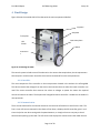
April 5,2012 Dr. Julio Militzer Dalhousie University 6299 South Street, Halifax, NS B3H 3J5 Dear Dr. Militzer This is design team 10’s submission of the Final Design Report, due April 5, 2012, as requested in the Design Project Handbook. This report is titled Final Design Report, Self-Balancing Robot. The purpose of the report is to outline our final design decisions, explain and analyse our testing, and give out thoughts and recommendations for the project. If you have any question concerning our project, please contact any of the members of Group 10. Sincerely Luc Malo, Jeremy Stewart, Renske Ruben and Gregory Ryan Final Term Report Self-Balancing Robot – Group 10 April 5th, 2012 Luc Malo Renske Ruben Gregory Ryan Jeremy Stewart Dr. Bauer Final Build Report Self-Balancing Robot Group 10 Abstract The following report discusses the design selection, assembly and testing of the self-balancing robot (SeBaRo) project by group #10. The purpose of building SeBaRo is so that systems I and II students have a hands-on demonstration of how PID control works. SeBaRo was built to be engaging and interactive as well as a safe and reliable classroom demonstration. The design includes a shock absorption system for durability, easily implementable controls for student interaction, data collection options and intuitive mechanisms for easy adjustments, disassembly and control. A full set of tests were done to ensure the robot performs to specifications. These specifications include durability, interactivity and stability of the robot. The different tests prove that SeBaRo has met all of the criteria that were listed back in September. Some of these tests include a full demonstration done for the current Systems I class, one-on-one interaction of SeBaRo with students, performance comparisons of different PID gains on its balancing and multiple failures to determine its durability. Recommendations are made on what can be done to add to SeBaRo in the future. There are many different options to enhance the demonstration aspect that were past the scope of this project. Page 1 of 39 Final Build Report Self-Balancing Robot Group 10 Table of Contents Abstract ......................................................................................................................................................... 1 Table of Contents .......................................................................................................................................... 2 Table of figures ............................................................................................................................................. 3 1 Introduction .......................................................................................................................................... 4 2 Design Requirements ............................................................................................................................ 5 3 Design Process ...................................................................................................................................... 6 3.1 Balancing method............................................................................................................................ 6 3.2 Angle measurement ........................................................................................................................ 7 3.3 Shock absorption ............................................................................................................................. 7 3.4 Student interaction ......................................................................................................................... 9 3.5 Chosen Design ................................................................................................................................. 9 4 Final Design ......................................................................................................................................... 11 4.1 Control system .............................................................................................................................. 11 4.1.1 Controller................................................................................................................................ 11 4.1.2 Communication ...................................................................................................................... 11 4.2 Drive System .................................................................................................................................. 12 4.3 Chassis ........................................................................................................................................... 12 5 Design analysis .................................................................................................................................... 15 5.1 Model ............................................................................................................................................ 15 5.2 Sensors .......................................................................................................................................... 16 5.3 Motor/Torque ............................................................................................................................... 18 5.4 Power ............................................................................................................................................ 18 5.5 Durability/shock absorption .......................................................................................................... 19 6 Assembly ............................................................................................................................................. 20 6.1 Deviation of labour ........................................................................................................................ 20 6.2 Procedure ...................................................................................................................................... 20 6.3 Accessibility ...................................................................................... Error! Bookmark not defined. 7 Safety Issues ........................................................................................................................................ 22 8 Testing ................................................................................................................................................. 23 8.1 Balancing and operation ............................................................................................................... 23 8.2 Demonstrative Aspect ................................................................................................................... 27 8.3 Durability ....................................................................................................................................... 31 8.4 Battery ........................................................................................................................................... 32 9 Budget ................................................................................................................................................. 33 10 Results ................................................................................................................................................. 34 11 Conclusion ........................................................................................................................................... 35 Appendix A – Gantt Chart ........................................................................................................................... 36 Appendix B – Technical Drawings ............................................................................................................... 37 Appendix C – SeBaRo Manual ..................................................................................................................... 38 Page 2 of 39 Final Build Report Self-Balancing Robot Group 10 Table of figures Figure 1: Internal pendulum to balance robot.............................................................................................. 6 Figure 2: Motor driven balancing robot........................................................................................................ 7 Figure 3: Passive safety feature - bumpers ................................................................................................... 8 Figure 4: Passive safety feature - Kickstand.................................................................................................. 8 Figure 5: Student interaction possibilities .................................................................................................... 9 Figure 6: Final design of robot .................................................................................................................... 11 Figure 7: Exploded view of robot ................................................................................................................ 13 Figure 8: Shock absorption system internal view ....................................................................................... 14 Figure 9: Internal parts................................................................................................................................ 14 Figure 10: Free body diagram of system..................................................................................................... 15 Figure 11: Simulink model of the model ..................................................................................................... 16 Figure 12: Test of Accelerometer, Gyroscope and Kalman filter ................................................................ 18 Figure 13: Student implemented PID gains - 11, 40, 0.05 .......................................................................... 24 Figure 14 PID gains of 20, 30 and 0.2 respectively ..................................................................................... 25 Figure 15: PID gains of 25, 25, 0.1............................................................................................................... 26 Figure 16: Maximum balancing angle attained to date .............................................................................. 27 Figure 17: Class room demonstration ......................................................................................................... 28 Page 3 of 39 Final Build Report Self-Balancing Robot Group 10 1 Introduction The objective of our design is to clearly present an application, as well as demonstrate concepts and theory of control systems. SeBaRo will balance itself using a control method taught in MECH 3900 and MECH 4900 at Dalhousie University. The design will provide students with the opportunity to interact with the robot by adjusting control parameters. The effect of the adjustments will be obvious by the changes in the robot’s ability to balance. The design process began with determining the basic criteria and requirements that the robot needs to abide by. Brainstorming then followed to find different methods of meeting those requirements. The final design was chosen by comparing the different options through their ability to illustrate concept, their safety, their usability, their expected lifetime and their inherent complexity. The final design is described in three main parts; the control system which acquires the angular position of the robot and uses it to direct the motors, the drive system which mechanically balances the robot and the chassis which houses the entire robot. Once the final design is completed analysis is carried out to the exact characteristic requirements of the different components. This includes the sensitivities of the sensors, the torque from the motors, the power from the battery, the shock absorption capabilities and the accessibility. Finally, testing is carried out on the final product to ensure its ability to meet the original criteria. Testing is done on the performance of the robot in its ability to balance, to demonstrate the concept of control systems and to function overall. It is found that the robot functions as designed and meets the design constraints and criteria initially described at the beginning of the project. With supplementary functions added to the robot, it is concluded that the robot surpasses expectations. A detailed budget and schedule is included in the report as well as the SeBaRo user manual. Page 4 of 39 Final Build Report Self-Balancing Robot Group 10 2 Design Requirements The design constraints and criteria that the robot is required to meet are as follows in order of importance: 1. The robot shall balance via an internal control system for a minimum of 15 minutes, while subject to no major disturbances 2. The device shall be safe to operate in a classroom and laboratory setting 3. The device shall balance on a surface area of: 0.7 m x 0.7 m 4. Physical size of device shall not exceed: 120 mm x 400 mm x 600 mm (w/l/h) 5. Maximum mass of the device: 10 kg 6. The device shall be capable of withstanding a minimum of 40 balancing failures 7. It shall be possible for students to implement their own control parameters 8. The electronic components shall be accessible for repairs, requiring less than three minutes to expose internal components 9. The cost of the project is to be less than $1500 Various reports and memos are to be submitted to adhere to the project guidelines listed on the course website. The following deliverables have been submitted: Design Requirements memo October 3rd 2011 Design Selection memo November 7th 2011 Build Report November 21st 2011 Fall Term Report December 7th 2011 Individual Lab book December 7th 2011 WWW webpage December 7th 2011 Final Build report January 16th 2012 Final Term report April 5th 2012 Page 5 of 39 Final Build Report Self-Balancing Robot Group 10 3 Design Process To simplify the process of choosing the final design, the ideas were broken intro four main sections: how the robot will balance, how it measures its angle, how to ensure it is a safe and robust device and how the students will learn from it. Each section was like a puzzle piece and the final design was chosen by taking the best of each section. Brainstorming was done on each section to find different possibilities and each was given a score to compare. 3.1 Balancing method There are basically two fundamental methods to balance an object: shifting its pivot point below its center of mass or shifting its center of mass above its pivot point. This section goes over the two methods and the pros and cons of each. The other way to position the center of mass above the pivot point would be to essentially apply a force at the mass to shift its location. This can be done by using a weighted pendulum powered by a motor. As the pendulum swings to one side, the center of gravity shifts with it because the pendulum is a large portion of the robots total weight. This option would also give the opportunity to balance the robot at odd angles by leaving the pendulum extended. Figure 1 is a drawing of a shifting mass pendulum. Figure 1: Internal pendulum to balance robot To shift the center of mass above the pivot point is to have the force acting on the pivot. The pivot point could be moved slightly past the center of gravity essentially catching it, by driving the wheels. This method would require a motor to power the wheels in both the forward and backward directions. By having motors attached to the wheels, it also becomes possible to have the robot move around while it balances. Figure 2 is a drawing of the robot balanced by motors. Page 6 of 39 Final Build Report Self-Balancing Robot Group 10 Figure 2: Motor driven balancing robot 3.2 Angle measurement The robot needs to be able to determine its angular position to know whether it is balancing and if not, how much it needs to maneuver to correct itself. One possible way to accomplish this is to use a range finding sensor to measure the distance from the pendulum to the ground and obtain balancing position information. This is, however, a roundabout way of finding the balancing point, which is an angle. A combination of a gyroscope and accelerometer is another more direct option for finding the balancing point. The two sensors are required to obtain the angular position using sensor fusion filtering to combine measured angle from the accelerometer and integrated angular velocity from the gyroscope. Due to the multiple inputs, this is a more complicated design, but it illustrates the robots balancing ability the best. 3.3 Shock absorption The robot needs to be robust to handle balancing failures (where the robot falls down either due to too strong of an input or bad system parameters) therefore it requires suitable shock absorption to prevent damage to itself. There are two routes to consider, the first is passive safety features and the second is active safety features. For passive safety features, the casing of the robot itself could have shock absorption built into it via energy absorbing materials or devices (such as rubber, springs, etc.). The components within the robot would need to be placed so that they do not interfere with the case’s ability to compress while absorbing impacts and one side of the casing would not be able to be directly connected to the wheels Page 7 of 39 Final Build Report Self-Balancing Robot Group 10 and would need to use some medium to connect to the rest of the case. Figure 3 is a drawing of bumpers with spring to take the shock of falling. Figure 3: Passive safety feature - bumpers An active safety feature could be to have a kick stand come out when the robot reaches its “point of noreturn” (the angle past which it is no longer able to catch itself when falling). This kick stand would catch the robot before it hits the ground reducing the amount of impact it would feel. This feature would need to be controlled by the robot itself once it realizes it will not be able to catch itself and then the kick stand would be deployed. Figure 4 is a depiction of the feature. Figure 4: Passive safety feature - Kickstand Page 8 of 39 Final Build Report Self-Balancing Robot Group 10 3.4 Student interaction A potentiometer would be easy to use and understand. In real-time, the students would be able to see how the system reacts when the gain is altered. It would also be a quick and pain-less process to change the gains. On the other hand, there would be more components required for the robot, increasing the cost, and would be more complex to put together. Controlling the gains by changing the in-code values does not require additional hardware and is simple to do. However, it would be a longer process to change the gains and may require partially dismantling the robot. Figure 5 is a drawing of the possible ways students can interact with the robot: an LCD screen that shows the data and a remote controller where the PID gains are implementable. Figure 5: Student interaction possibilities 3.5 Chosen Design The following design selection matrix, Table 1, is used to aid in the design selection process. Four criteria are scored with equal weight from 0 to 3. The criteria are: illustration of control systems theory, simple to construct, safe and easy to use, and long lasting. A high score means the idea matched well with the criteria. A low score indicates the idea did not match well against the criteria. Cost is not considered a criterion due to the low variation in costs depending on the quality of the designed feature. Page 9 of 39 Final Build Report Self-Balancing Robot Group 10 Table 1: Design selection matrix Category Idea Illustrates Concept Design Complexity Safety & Usability Life time Sum Balancing Method Positioning the center of mass Positioning the pivot point 3 2 1 2 8 3 3 3 2 11 Accelerometer and Gyroscope 3 2 3 3 11 Range Finder Sensor 2 3 2 3 10 Kick Stand 3 2 1 1 7 Rubber Stoppers 3 2 2 1 8 Shock Absorption Material Adjustable PID gains 3 3 3 3 12 2 3 3 3 11 Student Implemented Control System Record data for offsite analysis 3 1 2 2 8 3 1 2 3 9 Angle Measurement Safety and Robustness Student Interaction Page 10 of 39 Final Build Report Self-Balancing Robot Group 10 4 Final Design Figure 6 shows the outside shell of the robot with the main components labelled. Top plate Side plate Front plate Interaction plate plate LCD Screen Wheel Protrusion s Figure 6: Final design of robot 4.1 Control system The control system includes most of the electronics: the sensors that acquire data, the microprocessors that analyses it and the motor controllers that receives commands from the microprocessors. 4.1.1 Controller The main component of the controller is the microprocessor located in the Arduino: the ATmega328. This device receives the voltages from the sensors and converts them to values the motor controller can read. The motor controller then converts the values to voltages to power the motor the required amount to balance the robot. The Proportional-Integral-Derivative controller is coded into the Arduino’s microprocessor. 4.1.2 Communication There are two methods for the internal devices to communicate information to and from the user. The first is via an LCD screen mounted in the chassis of the robot, it displays the PID controller gains in realtime to help the user when tuning with the potentiometers, or simply to have an easy way to check them without opening up the code. The LCD screen also displays the various menus that allow the user Page 11 of 39 Final Build Report Self-Balancing Robot Group 10 to change some of the control systems, or put the robot into one of several modes. The actual controls are mounted to the side plate as a set of three buttons and three knobs. The second method of communication from the robot to the user is via Bluetooth. This allows for wireless communication between the robot and another Bluetooth device, both a computer and a cellular phone. The wireless connection allows the user to change certain variables’ values in the code while the robot is running. The wireless connection also allows for the user to control the position of the robot. This means that the user can drive the robot around to get to different locations. 4.2 Drive System The drive system consists of the different parts that will contribute to the robots movement when it is balancing. This includes the motor, wheels, and batteries. The self-balancing robots wheels will be driven by a Pololu 12V 29:1 gear motor. This motor was chosen because it is relatively low cost compared to other similar motors, and it has enough torque to control the pendulums estimated weight. The motor will be driving a pair of Devantech 125mm wheels. The Devantech wheels were chosen to be larger than the depth of the chassis to avoid the chassis making contact with the ground during balancing. These wheels were found to have extremely hard rubber wheels that adversely affected the ability for the robot to balance, so a foam rubber tread was secured to the wheel. This tread increases the wheel contact area and allows the robot to balance over a wider range of gains. The Pololu motors require 12 volt and 300mA when in free-run; we have thus selected the GENS ACE 5000mAH 4S1P 14.8V 25C Lipo battery. Lipos are very lightweight, rechargeable, and have long life expectancies if properly cared for. 4.3 Chassis The robots chassis is made up of three main sections, the casing, the shock absorption system and the internal brackets. The casing is meant to serve as the frame work for the robot, holding all of the internal components in place. The shock absorption system is to protect the robot from sudden impacts due to high inputs or balancing failures. The internal brackets hold the control system electronics, and battery, holding them securely to the casing. Figure 7 is an exploded view of all the different parts of the robot. Page 12 of 39 Final Build Report Self-Balancing Robot Group 10 Figure 7: Exploded view of robot The casing is made of seven parts to make up the six sides of the robot. The front plate is where the LCD screen display of the control system response is secured. The backside is split into two plates, one designed to be removed easily to allow maintenance access and one secured to keep the rear plate together during operation. The top and bottom plates are where the bracket system is secured, and they are in turn secured to the two side plates. The motors, shock absorption system, interaction devices, and casing plates are fastened to the side plates which also act as a portion of the shock absorption system. The shock absorption system is made of two main parts, the bumpers and the shock absorption material. Figure 8 shows a section view of the shock absorption parts. The bumpers are simple bolts with rubber tips to prevent damage to the surfaces the robot falls on. These bolts are slid through mounting holes in the front and rear plates as well as the side plates. The bolts are free to move axially. The shock absorption material is placed between the side plates and the front/rear plates so that when the robot faces an impact, the bolts push against the face/rear plates which compresses the shock absorption material and distributes the load against the side plates. The bolts are secured with nuts, using just enough tension to secure the front and rear plates without compressing the shock absorption material. Page 13 of 39 Final Build Report Self-Balancing Robot Group 10 Front plate Top plate Protrusion Neoprene rubber Back plate Flange s Left Side plate Figure 8: Shock absorption system internal view The internal brackets are designed to secure the internal components of the robot to the casing. Figure 9 shows the internal components of the robot. The sensors and processor are mounted to a thin aluminum plate connected the side plate without the controls. The battery housing secures the battery to the top plat. Battery holder Accelerometer mount Sensor mount Motor Wheel Base plate Figure 9: Internal parts Page 14 of 39 Final Build Report Self-Balancing Robot Group 10 5 Design analysis Analysis for the different components was done to ensure the design requirements were met. Numerical calculations were made on the motor requirements and on the sensitivities of the sensors. Simulation testing was done when for the geometry of the robot using the model found in section 1. 5.1 Model A free body diagram of the system is shown in figure 10, where the two main components of the body are considered separately. The transfer function is derived to create a simulation for the system on Matlab where a fine-tuned PID controller is found. Tm Fy Fy Tm Fx Fg Fg Ff Fx Figure 10: Free body diagram of system A Newtonian approach was taken to derive the equations where the sum of the forces and moments were used. Once the equations of motion were found for the pendulum and wheel, the output of the motor was implemented. ̈ ( ) ̈ ( ̈ ) ( ( Page 15 of 39 ̇ ) ) ̈ ( ( ) ) ̇ (1) (2) Final Build Report Self-Balancing Robot Group 10 The non-linearized equations were also built in Simulink to obtain the model. This model would allow for a more realistic response by adding noise and step inputs to the system. Figure 11 is the Simulink model of the system. Figure 11: Simulink model of the model 5.2 Sensors Based on the specification sheets from the sensors, the resolutions are calculated and can be seen in Table 2. Resolution increases with a more sensitive device or with a higher bit analog to digital converter. For the final design, both changes will be implemented to increase resolution. Table 2: Theoretical angle resolution results Device: Accelerometer Gyro* LIS244ALH ADXL203 10 Bit ADC 0.84° 0.84° 12 Bit ADC 0.18° 0.21° IXZ500 ADXRS610 0.016° 0.0054° 0.0040° 0.0013° *Assumes a control loop frequency of 100Hz Experimental testing was performed to check resolution calculations; the results are shown in Table 3. The accelerometer tested is LIS244ALH. The experimental results match the theoretical results, verifying the method of calculation. Page 16 of 39 Final Build Report Self-Balancing Robot Group 10 Table 3: Experimentally determined resolution Consecutive Angle Measurements (°) 0.84° 0° -0.85° -1.69° -2.53° Measured Resolution (°) 0.84° 0.85° 0.84° 0.84° -7.62° -8.47° -9.33 -10.18 0.85° 0.86° 0.85 The accelerometer zero-g offset and sensitivity constants are experimentally determined in table 4 below. These values match the values found in the specifications, verifying measuring technique and methods. The specifications list the Zero-g offset as 1.65 V and the sensitivity as 222 mV/g assuming a Vcc of 3.3V. Table 4: Statistical calculation of zero-g offset and sensitivity for the LIS244ALH accelerometer Acceleration: Samples Max (V) Min (V) Mean (V) STD (V) Precision Uncertainty(V) Resolution Uncertainty (mV) (10 Bit ADC) Zero-g Offset (V) Sensitivity (V/g) +g 694 1.877 1.896 1.883 0.003 ±0.003 3.22 -g 1042 1.452 1.432 1.440 0.003 ±0.003 3.22 1.662 V ± 0.0044 V (95%) 0.222 V ± 0.0044 V (95%) Three angle measurements are plotted in the figure below: the accelerometer angle, the gyro angle, and the complimentary filtered angle. The results verify the presence of unwanted acceleration measurements and gyro drift (due to integration). Although the figure below shows the filter to be working, further development on the filtering process is required to ensure a clean and accurate angle measurement. Page 17 of 39 Final Build Report Self-Balancing Robot Group 10 Figure 12: Test of Accelerometer, Gyroscope and Kalman filter 5.3 Motor/Torque The requirements of the motor are calculated by finding the maximum force the pendulum would have on the wheel. The max angle that the robot would have that can be corrected is six degrees and the max weight is 4kg and the radius of the wheel is 0.2 m. The max torque requirements are then calculated as: (3) ( ( ))( ) (4) (5) This is what the chosen motor supplies as max torque and is, therefore, sufficient. 5.4 Power While both the Arduino and the motors are being powered by the battery, the Arduino takes nearly no current therefore is negligible compared to the motors. The motors required a 12V supply and have a 5A stall. The required battery then needs to be at least 12 V, and max torque used is 5A. The Li-Po batteries allow for easy recharging and a four cell is cost efficient and supply 14.8V. The ampere chosen is Page 18 of 39 Final Build Report Self-Balancing Robot Group 10 5000mAh which would allow for at least an hour of continuous run time, if the robot was at full torque the whole time. This is sufficient to demonstrate during a full class. 5.5 Durability/shock absorption Analysis on the required shock absorption is done to ensure when the robot “fails” and falls over, it would not damage any of the internal components. The forces involved were assumed to be the highest possible for a balancing failure with a safety factor of two. The force was assumed to be similar to dropping the robot straight down. ( ) (6) The mass of the robot (m) is estimated at 3.5 kg leading to a total force of 68.67 N. With this force, and a designed spring material thickness of one centimeter to reduce bulk we assumed a compression of one half. Using these numbers a modulus of elasticity can be found. , Where is the change in length, , (7) is the original length, F is the force involved, A is the area the force is applied to and E is the modulus of elasticity. The area the force is applied to is determined by the geometry of the robot side plate (reference draft drawing, side plate). The modulus of elasticity was found to be 1.3734E6 Pa. Most elastomer materials used in shock absorption do not advertise the modulus of elasticity of the given material, but do relate it to the Shore hardness, or ‘durometer’ rating. The Shore hardness can be found with the following equation where E is in MPa: ( ( ( ) )) where S is the Shore hardness of the material. It is found to be 38.5931 which rounds to 40. A durometer rating of 40 is very common in shock absorption elastomers, and neoprene rubber is also commonly used for this application. Page 19 of 39 (8) Final Build Report Self-Balancing Robot Group 10 6 Assembly This section explains the different aspects of the assembly of the robot including the division of labour, how the parts are held together and how to easily disassemble the robot to reach the internal components. 6.1 Deviation of labour The construction of the parts will all be done by Dalhousie Technicians. Each part is fully drawn in Appendix C. The majority of the electrical components are assembled by the team with the exception of the battery components, which is done by Dalhousie technicians. The assembly of all purchased and built parts is done by the team. 6.2 Procedure The following is a step-by-step procedure to put the robot together Ensure that all components are accounted for and mounted on PCB if required Secure PCB to mounting plate using 4 X 3M screws Secure Motor controller to mounting plate 2X3M screws Secure mounting plate to side plate using 3 X 3M bolts Secure first electric motor to side plate using 3 X 3M screws Secure panel mount power switch Attach 4 X LED's, 3 X push buttons, 3 X potentiometer dials, and 2 X USB panel mount receivers to the interaction plate Secure the interaction plate to the side plate with 2 X #6-38 thumb screws Secure second electric motor to side plate using 3 X 3M screws Secure panel mount switches Secure bottom rod bracket to bottom plate using 4 X 5M bolts Secure side plates to bottom plates using 8 X 3M screws with spacers Attach shock absorption pad to front plate with 4 X 10M bolts with rubber stopper tops (no nuts yet) Secure front plate and absorption pad to side plates using the same 10M bolts as previous step and use the nuts to secure them lightly together Connect electrical components as per circuit diagram Attach bottom back plate to absorption pad with 2 X 10M bolts with rubber stopper tops Secure bottom back plates and lower portion of absorption pad to side plates using 2 X 10M bolts and secure lightly with nuts Slide upper back plate behind lower back plate Attach upper back plate to absorption pad and side plates with 2 X 10M bolts with rubber stopper tops and secure lightly with nuts Page 20 of 39 Final Build Report Self-Balancing Robot Place LIPO battery in battery bracket Secure battery bracket and rod assembly to top plate Connect battery to electronic components Secure the top plate to the side plates using 4 X #6-38 thumb screws Attach wheels using 3/32 Allan key 6.3 Accessibility To reach internal electronics once SeBaRo is fully assembled and in operation: Make sure the power switch is in the off position (zero side is pressed down) Remove the four #6-38 thumb screws securing top plate to the side plates Carefully remove the top plate by pulling it straight up Disconnect the battery and place the top plate and the battery off to the side Remove the internal nuts securing the back plates upper bolts Remove the back plates upper bolts Pull up the upper back plate and place it to the side The electronics should be fully accessible within a total time of less than 3 minutes. Page 21 of 39 Group 10 Final Build Report Self-Balancing Robot Group 10 7 Safety Issues Lithium Polymer batteries (which is what will be used for the robot) have been known to explode on occasion if a short-circuit occurs. To mitigate this, the assembly of the electrical components were supervised by the technicians. Also, the team will buy an anti-explosion LIPO storage bag which can be used when charging the battery. The safety bag would contain any fire or explosion that could occur if the battery is short-circuited. It will also be important to regularly carry out a visual inspection of the battery, especially after removing it from the robot. This inspection will be to look for any outside damage to the battery and especially to check for any damage to the insulation on the wires. If damage is found it should be repaired immediately and if repairs are impossible the battery should be replaced. The battery also has an ideal safe operating range of 3.2 to 4.2 volts. The Mechanical Engineering department at Dalhousie University has a battery charger with built in features that prevent overcharging the battery beyond 4.2 volts. The use of other chargers is not recommended, should the battery be allowed rise significantly above 4.2 volts or to drop significantly below 3.2 volts the battery should be replaced to avoid malfunctions. Since there are multiple cells, care needs to be taken to ensure that they are balance. While they do not need to have the exact same voltage, a range of 0.05 V is recommended. Any more than that then the battery needs to be charged. Page 22 of 39 Final Build Report Self-Balancing Robot Group 10 8 Testing This section will go over the type of testing that will be performed. The testing is to ensure that the criteria set early in the selection phase will be met and that the robot performs as expected. Testing is also done to continually improve its performance by fine-tuning the control system and its features. 8.1 Balancing and operation The main criterion was for the robot to balance for 15 minutes without any external inputs. It was determined early on in the testing of the robot that this was very easily achievable with nearly any PID input and therefore the majority of the balancing testing was done with an input force to the robot to destabilize it and see how it corrects itself. These inputs, or pushes, are very difficult to gauge or measure and therefore were described as a small, medium or large push. The robot has the ability to communicate with a computer to output the data it reads internally. This data includes the filtered angle from the gyroscope and accelerometer, the encoder values and the voltage the motor-controller sends to the motors. From this data, analysis can be done to determine many different aspects to the performance of the robot, including: Maximum angle the robot can correct Maximum speed the robot achieves Typical oscillation period and span PID performance Different PID’s were inputted and then a small, medium and large push was given to see how the PID gains affected the performance of the balance of the robot. It is noted that the purpose of the project is not to find the optimal gains for the PID controller; therefore this was not done during the testing. The robot is meant to demonstrate how the PID works. The robot was being shown to different students, at one of these demonstrations the student was interested to see what would happen if the proportional gain was set to a very small number. The student implemented the PID gains himself once a short explanation of how to do so was given. The following figure shows the performance with a small, medium and large push. The PID gains implemented were 11, 40 and 0.05 respectively. Page 23 of 39 Final Build Report Self-Balancing Robot Group 10 Figure 13: Student implemented PID gains - 11, 40, 0.05 The filtered angle from the two sensors is shown in the first of the three graphs. The position of the robot relative to the location it started at is the second, this is found by the output of the encoder and knowing the circumference of the wheel. The third graph is the voltage the motor controller sends to the motors. The three different pushes are best distinguished by the position graph, as pointed out by the arrows. The oscillations seen are because the robot does not balance perfectly at zero degrees, this is impossible due to the many external variables (wind, air pressure, unbalances/vibrations in the floor). These oscillations depend on the gains implemented and at these specific ones it can be seen that the angle is generally between +/-1.5 degrees and requires +/- 2 V to sustain it. The robot is also programed to return to its starting position once equilibrium is reached. This also depends on the gains implemented, for example after the medium push the graph shows that it took over 30 seconds to return to its original position after it found balance. The reason for such a long delay is that the balance and position controllers are fighting each other; the balance controller will not allow the robot to destabilize to return to the original position. All three graphs together show many different things. First, the max angle reached was due to the large push and was 6.3 degrees. The distance travelled due to the large push was quite disproportional to the Page 24 of 39 Final Build Report Self-Balancing Robot Group 10 two smaller ones as seen not only by the position graph, but also the angle it reached and voltage the motors received. The voltage outputted by the motor controller was 10 V to support this, versus the 5 V from the medium push. An interesting aspect of the voltage graph is that the voltage required to reach equilibrium after the small push was only marginally larger than what is used to keep the robot balanced. A few changes were done to the gains to see the effects. The gains used for this experiment was 20, 30 and 0.2 respectively. Figure 14 PID gains of 20, 30 and 0.2 respectively The first difference between the two is the angle at which it oscillates: instead of a three degree range as with the previous gains, it is approximately a one degree range. This same phenomenon can be seen for the position plot where the oscillation distance is quite small, approximately three cm. Another difference is that from the large push, the robot overshot its original position prior to gaining equilibrium. We can also see that the robot did not require the full ability of the motor controller to do this as it only drew a peak of 6 V. Page 25 of 39 Final Build Report Self-Balancing Robot Group 10 The next figure is using another set of gains, 25, 25, 0.1, and shows the importance of the derivative control for overshoot. A note should be made that there were two medium pushes as seen between 20 and 30 seconds. The large push began at 42 seconds. Figure 15: PID gains of 25, 25, 0.1 At first the gains looked like successful gains. Minimal oscillations at equilibrium are seen for angle, 0.5 degrees, and position, 2cm. The robot finds stability relatively easily with the small and medium pushes. However, when a large push is inputted the robot becomes unstable. As seen around the 50 second mark, the robot overshot quite a bit and returns even farther than originally after the push. The change in slope seen just prior to the 60 second mark is when the robot is “caught” to help it stabilize. While the angle never became as large as the first experiment reached, it could not stabilize. Obviously these gains were not very good. The graph below shows the max angle the robot was able to achieve and regain balance, at 6.54 degrees (when taking into account that the robot was balancing around one degree). This angle also corresponded to the max voltage output and speed. Page 26 of 39 Final Build Report Self-Balancing Robot Group 10 Figure 16: Maximum balancing angle attained to date From the position values, the speed that the robot reached was calculated to be 1.8 m/s. This corresponds to wheel speed of 264 RPM when taking into account the wheel radius. This value makes sense considering the free run speed of the motor is specified to be 360 RPM. The position graph also shows that the robot required nearly 4 meters to correct itself. 8.2 Demonstrative Aspect The main task of the robot is to be a hands-on, real-life demonstration of what control systems are and how they work. Therefore, the most important test done was to have a demonstration to the systems I class. This demonstration was not done at the best time during their semester since they had already completed that component of the course a few weeks previous. The demonstration was done to teach something new to the class and increase their understanding in systems control. The aim was also to increase their interest, since interest in a subject aids in learning. The demonstration was done during a regular class period, for a duration of 50 minutes. A quick introduction to the project was first given and followed by a review of PID control. This opening presentation took 10 minutes so as to insure the class understood the purpose of the robot and how it Page 27 of 39 Final Build Report Self-Balancing Robot Group 10 was controlled. The majority of the demonstration was showing what the robot could do and how the PID effected its ability to balance. The figure below is a snapshot of the demonstration done. Figure 17: Class room demonstration A few things that should be added/changed for future presentation are listed below: Have students handle the robot themselves and try different gains Smaller groups of students to insure all have the ability to see / try the robot Longer question period Initially start with better gains to show its ability to correct a push The demonstration ended with a question period. A highlight of the questions asked is summarized below with their responses. Page 28 of 39 Final Build Report Self-Balancing Robot Group 10 Table 5: Summary of questions asked during class demonstration Question Response Why do you need multiple PIDs? To control multiple things: to keep the two motors in sync we use one set of PID gains,different PID gains are used for the position control based on how far away the robot is from its starting point, and then depending on the location (slope of the ground, temperature, surface friction, etc) the gains needed to balance the robot change. Can it balance on a slope? Yes, but it requires different PID gains the balancing on a flat surface. What is the max angle it can recover at? From the testing done, at least 6.5 degree angle How do you pick the gains? You tune them for the desired results for the different circumstances, i.e on a slope, with a disturbance, on the spot. Do you have the ability to move it a certain Jeremy wrote a cell phone app that lets us drive it distance and have it reach equilibrium there? around by remote control, so yes. Can it tune its gains itself? No, but with some good coding that should be possible, but it is beyond our scope and abilities. A survey of the class was taken at the end to gather the overall response of the class. The survey consisted of a few yes or no questions with a comments and recommendation section. Overall the feedback was mostly positive where the majority of the students learned something and found the demonstration interesting. There were 58 students that filled out the survey, the majority of the class, and all were anonymous. Page 29 of 39 Final Build Report Self-Balancing Robot Group 10 Table 6: Survey responses Survey Questions Response (% yes) Did you like our demonstration/ find it interesting? 100% Did you understand what and why we were demonstrating? 98% Did you have a good grasp on systems control before this demonstration? Did this demonstration increase your understanding of PID control? 63% Did this demonstration increase your interest in systems? 82% Was the robot easy to use? 88% Would having a hands-on model like SeBaRo have helped you when learning control? Did you learn something from our demonstration? 98% 93% 97% This survey shows that a large part of the class does not have a good understanding of the concepts of systems and 93% of responders said that the demonstration increased it. All of those surveyed said that they found the demonstration interesting. Some of the comments and recommendations that were included on the survey are: That was pretty cool. Very interesting! Awesome demonstration. Good job! Biggest value for me was better understanding of PID controls. Really good job! It was a cool, practical systems example. Well done. Informative. I think this is a great idea that will be useful in our next systems class. Cool project. Systems sucks but you actually made it interesting, being able to see a tangible use for the stuff we do in class was great. It looks tedious and I don’t want to deal with it. This list isn’t the entirety of the comments given, but do show the overall feedback from the class. With the exception of one negative comment, the comments were all positive. The negative comment is the last listed above and is a valid argument. This highlights the necessity of making the robot easy to use. Page 30 of 39 Final Build Report Self-Balancing Robot Group 10 8.3 Durability One of the original criteria was that the robot could sustain 40 failures. These failures are when the robot falls overdue to improper gains or if too much of a force (push) was executed. During routine operation and testing of the robot, it has sustained well above the 40 failures it was designed for. Addition assessments were done to see what was required to achieve failure and trials on different surfaces was carried out. Surfaces included: Hardwood Tile Ceramic Thin carpet Tabletop It is noted that while the robot is designed to be able to balance on top of a classroom podium, it is not supposed to withstand a fall from such a height. All falls tested were from the balancing position and from no higher. Any demonstration of the robot failing should be done from the balancing position in a place where it will fall flat on the ground and not over a ledge. Throughout every fall that the robot withstood, the only damages caused were, to the wheels and when the rubber stoppers. The damage to the wheels was the thin foam we attached to them was peeled off. The rubber stoppers were detached after a fall which ended with SeBaRo dragging along the floor for a short distance. The wheels were quickly and easily fixed with measures implemented to insure it could not happen again. The rubber stoppers have also been reattached, and we have ordered new stoppers which we believe will withstand dragging along the floor better. These rubber stoppers are only meant to stop SeBaRo’s protruding bolts from damage the surfaces it falls on after failures and are not needed as a part of the shock absorption system. The robot has also survived high velocity impacts with standing objects such as chairs and table legs with no visible damage. These types of collisions should not damage the internal components, but could dent the chassis over time making disassembly and reassembly more difficult and are thus not recommended. Page 31 of 39 Final Build Report Self-Balancing Robot Group 10 8.4 Battery The battery mainly affects two of our design criterion; the weight and the length of time the robot can balance for. We determined the balancing duration was slightly more important and calculated that the required voltage to operate all of our hardware could be met by a 14.8 volt battery in section 5.4 above. Next looking at weight we chose to use a lithium polymer battery because of their high energy density (high energy to weight ratio). This choice minimized the weight impact of the battery while still granting us the required voltage and gave us a 5000 kWh capacity battery. In theory with 5000kWh operating at maximum torque the robot could last for one hour, but it was pointed out to us by Dr. Swan that this was in fact incorrect and as the torque went up the current drawn from the battery would decrease and the battery would likely last a great deal longer. During a day of testing that used the robot for approximately eight hours (non-consecutively), tuning the gains and pushing the robot, did not significantly deplete the battery. During a 20 minute testing session, where the robot was pushed repeatedly, the battery started at 3.7 volts per cell and ended at 3.67 volts. This was a testing session with constant inputs to SeBaRo while allowing it to return to its starting position. It is important to keep in mind that the battery does not discharge linearly; it will drain slower when it has more charge and as the charge goes down it will drain faster and faster. This was seen when the battery was tested again after 30 minutes of the same type of testing immediately after, and the average cell voltage was 3. It should be noted that if the voltage of the battery is below or near 3.5, it will deplete quickly. The time to charge the battery, of course, depends on the voltage it starts at. The one time the battery was completely depleted (at 3V per cell, 12 V total) it took 90 minutes to completely recharge. Page 32 of 39 Final Build Report Self-Balancing Robot Group 10 9 Budget The final budget is shown below; the $200 that was given to our project to build the prototype is included. The department granted the project $1500, for a total of $1700. SeBaRo therefore came out under budget by over $150. Table 7: Budget Part Name Supplier Unit Accelerometer ADXL203 RobotShop.com Gyroscope ADXRS610 RobotShop.com Micro-processor Arduino nano RobotShop.com 2 $34.00 $68.00 Motor Controller Pololu dual 13A, 16.6V RobotShop.com 1 $103.00 $103.00 LCD screen Serial Graphic 160x128 SparkFun.com 1 $79.99 $79.99 Bluetooth BlueSMiRF Silver RobotShop.com 1 $41.19 $41.19 Battery E-flite, 14.8V 4000mAh Greathobbies.com 1 $79.99 $79.99 Misc Electrical Wires, capacitors, resistors $200.00 $250.00 Motor Pololu 12V, 29:1 gear 1 Cost Total $128.70 $128.70 Incl w/accel RobotShop.com 3 $41.99 $125.97 motor w/ encoder Wheel Devantech 125mm RobotShop.com 2 $28.34 $56.68 Aluminum Aluminum utility grade Metals r us 1 $22.25 $22.25 3/56” thick 1x2ft Rubber Ball 5/8” 10 pack McMaster Carr 8 $0.99 $7.92 Neoprene Sheet, 12”x24” 30A Mcmaster Carr 2 $40.30 $80.60 Explosion bag Lipo safety sac Mighty small cars 1 $20.00 $20.00 PC Board Electronics board BatchPCB 2 $128.50 $128.50 Decals Dal and shell logo Vinyl FX 1 $37.60 $37.60 Bluetooth Bluetooth dongle Robotshop.com 1 $6.65 $6.65 Machining Dalhousie Techs Dalhousie 28 hr - Misc hardware Nuts/bolts/rods Shipping Subtotal Taxes $50.00 $50.00 $100.00 $100.00 $1,337.04 15% $200.55 Total $1,537.59 Page 33 of 39 Final Build Report Self-Balancing Robot Group 10 10 Results The design requirements are reviewed for evaluation: 1. The robot shall balance via an internal control system for a minimum of 15 minutes, while subject to no major disturbances 2. The device shall be safe to operate in a classroom and laboratory setting 3. The device shall balance on a surface area of: 0.7 m x 0.7 m 4. Physical size of device shall not exceed: 120 mm x 400 mm x 600 mm (w/l/h) 5. Maximum mass of the device: 10 kg 6. The device shall be capable of withstanding a minimum of 40 balancing failures 7. It shall be possible for students to implement their own control parameters 8. The electronic components shall be accessible for repairs, requiring less than three minutes to expose internal components 9. The cost of SeBaRo is to be less than $1500 Explanation in order of appearance: The robot will balance with a 3 cm amplitude for the duration of the battery life. The battery will safely last over 3 hours if left undisturbed. The robot is an interesting and engaging demonstration to systems students in both a personal and classroom setting. The robot can be tuned to have a 3 cm amplitude and will stabilize a small push within 10 cm. The robot’s size is 120 x 295 x 360 mm and weight is 4.3 kg. The robot has withstood over 40 failures on many different surfaces, including tabletop. The robot can be disassembled within 50 seconds to reach internal components and reassembled in 90 seconds. SeBaRo’s final cost was $1338 Page 34 of 39 Final Build Report Self-Balancing Robot Group 10 11 Conclusion The robot was a success. It is an interesting and engaging demonstration tool for systems students. It has met every requirement defined in September and has gained many additional features. The robot will be a great addition in both systems I and system II courses for students. Some recommendations would be to insure the students have the opportunity to use the robot themselves and implement their own gains to learn from them. Page 35 of 39 Final Build Report Self-Balancing Robot Appendix A – Gantt Chart Page 36 of 39 Group 10 ID Task Name 7 1 3 2 4 5 6 16 17 19 20 21 18 8 9 10 11 12 13 14 15 22 23 24 25 26 28 31 30 29 27 32 33 34 35 36 38 39 40 41 37 Prototype testing / improvements Work on Final build report Revise drawings of robot Finalise drawings with technicians Update Budget Update Gantt Chart Final build/design report for review by supervisor Final build/design report due Begin building Procurement of parts / material Machining Assemble electric circuit Assemble entire robot Complete assembled robot Controller Design Initial testing Design of the design Motor/power function Controller performance Robustness testing Possible additions to design Inspection of working device by supervisor Adjustments to design Misc building/assembly/machining Addition procurement Controller improvements Final testing Final design refinement Robustness testing Performance evaluation Inpection, testing require by date Write final build report Document final design Organize testing/results Final Project report for review by supervisor Lab books due Organize presentation Practice / rehearsal presentation Oral presentation days Project close out / turnover Final Project report due Duration 9 days 15 days 8 days 3 days 2 days 2 days 3 days 0 days 40 days 7 days 22 days 7 days 12 days 0 days 22 days 16 days 14 days 4 days 4 days 4 days 3 days 1 day 14 days 14 days 3 days 7 days 30 days 7 days 5 days 14 days 0 days 15 days 10 days 10 days 4 days 1 day 7 days 1 day 2 days 3 days 0 days Start Finish Sun 1/1/12 Sun 1/1/12 Sun 1/1/12 Mon 1/9/12 Mon 1/9/12 Mon 1/9/12 Fri 1/13/12 Mon 1/16/12 Mon 12/5/11 Mon 12/5/11 Mon 12/12/11 Mon 1/2/12 Mon 1/2/12 Fri 1/13/12 Mon 1/16/12 Mon 2/6/12 Mon 2/6/12 Tue 2/7/12 Sat 2/11/12 Wed 2/15/12 Sun 2/19/12 Wed 2/22/12 Thu 2/23/12 Thu 2/23/12 Fri 2/24/12 Mon 2/27/12 Thu 2/23/12 Thu 2/23/12 Mon 3/5/12 Sat 3/10/12 Fri 3/16/12 Mon 3/26/12 Mon 3/26/12 Mon 3/26/12 Thu 4/5/12 Mon 4/9/12 Mon 3/26/12 Mon 4/2/12 Wed 4/4/12 Fri 4/6/12 Mon 4/9/12 Page 1 Mon 1/9/12 Sun 1/15/12 Sun 1/8/12 Wed 1/11/12 Tue 1/10/12 Tue 1/10/12 Sun 1/15/12 Mon 1/16/12 Fri 1/13/12 Sun 12/11/11 Mon 1/2/12 Sun 1/8/12 Fri 1/13/12 Fri 1/13/12 Mon 2/6/12 Tue 2/21/12 Sun 2/19/12 Fri 2/10/12 Tue 2/14/12 Sat 2/18/12 Tue 2/21/12 Wed 2/22/12 Wed 3/7/12 Wed 3/7/12 Sun 2/26/12 Sun 3/4/12 Fri 3/23/12 Wed 2/29/12 Fri 3/9/12 Fri 3/23/12 Fri 3/16/12 Mon 4/9/12 Wed 4/4/12 Wed 4/4/12 Sun 4/8/12 Mon 4/9/12 Sun 4/1/12 Mon 4/2/12 Thu 4/5/12 Sun 4/8/12 Mon 4/9/12 ber 2011 January 2012 Dec 4, '11 Dec 11, '11 Dec 18, '11 Dec 25, '11 Jan 1, '12 SM TWT F S SM TWT F S SMTWT F S SMTWT F S SMTWT F S February 2012 March 2012 April 20 Jan 8, '12 Jan 15, '12 Jan 22, '12 Jan 29, '12 Feb 5, '12 Feb 12, '12 Feb 19, '12 Feb 26, '12 Mar 4, '12 Mar 11, '12 Mar 18, '12 Mar 25, '12 Apr 1, ' SM TWT F S SM TWT F S SMTWT F S SMTWT F S SMTWT F S SM TWT F S SM TWT F S SMTWT F S SMTWT F S SMTWT F S SM TWT F S SM TWT F S SMT 1/16 1/13 3/16 Page 2 012 May 2012 June 2012 '12 Apr 8, '12 Apr 15, '12 Apr 22, '12 Apr 29, '12 May 6, '12 May 13, '12 May 20, '12 May 27, '12 Jun 3, '12 Jun 10, '12 Jun 17, '12 Jun 24, '12 WT F S SMTWT F S SMTWT F S SM TWT F S SM TWT F S SMTWT F S SMTWT F S SMTWT F S SM TWT F S SM TWT F S SMTWT F S SMTWT F S SMTWT F 4/9 Page 3 Final Build Report Self-Balancing Robot Appendix B – Technical Drawings Solid Edge Schematics in order of occurrence: Face Plate Back Plate Back Plate Bottom Top Plate Top Plate Vents Top Plate Flattened Bottom Plate Side Plate Side Plate Motor Mount Side Plate Flattened Side Plate Interaction Side Plate Interaction Motor Mount Side Plate Interaction Flattened Control Panel Battery Bracket Battery Bracket Flattened Rod Bracket Rod Bracket Flattened Rod Bracket Bottom Rod Bracket Bottom Flattened Sensor Bracket Sensor Bracket Flattened Plate Assembly Exploded Bracket Assembly Exploded Page 37 of 39 Group 10 140.00 Break Corners O 10 X4 O 3 X4 82.00 95.00 101.00 240.00 300.00 122.00 200.00 Dalhousie University Project: Balancing Robot Team 10 Drawing: Front Plate Dwn By: Gregory Ryan Angles Course: Mech 4010 Qty: 1 +/- 0.25 º Material: 2mm Aluminium Scale: Units: SHEET 1 OF 1 1:4 Nov. 15 /11 mm Units : mm x. xx +/- .15 x. x +/- .25 x +/- .50 Date: Units : inches x. xxx +/- .005 x. xx +/- .01 x.x +/- .02 30.00 140.00 248.00 280.00 R 5.00 32.00 Dalhousie University Project: 10.00 Balancing Robot Team 10 Drawing: Back Plate Dwn By: Gregory Ryan Angles Course: Mech 4010 Qty: 1 +/- 0.25 º Material: 0.08" Aluminium Scale: Units: SHEET 1 OF 1 1:2 Nov. 15 /11 mm Units : mm x. xx +/- .15 x. x +/- .25 x +/- .50 Date: Units : inches x. xxx +/- .005 x. xx +/- .01 x.x +/- .02 200.00 140.00 Break Corners O 10 X2 20.00 50.00 Break Corners Dalhousie University Project: Balancing Robot Team 10 Drawing: Dwn By: Gregory Ryan Angles Course: Mech 4010 Qty: 1 +/- 0.25 º Material: 0.08" Aluminium Scale: Units: SHEET 1 OF 1 1:2 Nov. 15 /11 mm Back Plate, bottom Units : mm x. xx +/- .15 x. x +/- .25 x +/- .50 Date: Units : inches x. xxx +/- .005 x. xx +/- .01 x.x +/- .02 Reference Sheet 2 of 3 30 68 75 55 O5 mm X4 #10 Screw X4 200 52 49 96 75 Dalhousie University Project: Balancing Robot Team 10 Drawing: Top Plate Dwn By: Gregory Ryan Angles Course: Mech 4010 Qty: 1 +/- 0.25 º Material: 0.08" Aluminum Scale: Units: SHEET 1 OF Sheet of 13 1:2 Nov. 15 /11 mm Units : mm x. xx +/- .15 x. x +/- .25 x +/- .50 Date: Units : inches x. xxx +/- .005 x. xx +/- .01 x.x +/- .02 2 35 43 3 Dalhousie University Project: Balancing Robot Team 10 Drawing: Dwn By: Top Plate Vents Units : mm x. xx +/- .15 x. x +/- .25 x +/- .50 Date: Units : inches x. xxx +/- .005 x. xx +/- .01 x.x +/- .02 Nov. 19 /11 Angles +/- 0.25 º Scale: 1:1 Gregory Ryan Course: Mech 4010 Qty: 1 Material: 0.08" Aluminum Units: Sheet of 13 SHEET 2 1 OF mm 172 200 Dalhousie University Project: Balancing Robot Team 10 Drawing: Dwn By: Gregory Ryan Angles Course: Mech 4010 Qty: 1 +/- 0.25 º Material: 0.08" Aluminum Scale: Units: Sheet of 13 SHEET 3 1 OF 1:1.75 Nov. 15 /11 mm Top Plate Flattened Units : mm x. xx +/- .15 x. x +/- .25 x +/- .50 Date: Units : inches x. xxx +/- .005 x. xx +/- .01 x.x +/- .02 166 65 4 75 55 50 O 5 TYP 200 Dalhousie University Project: Balancing Robot Team 10 Drawing: Bottom Plate Dwn By: Gregory Ryan Angles Course: Mech 4010 Qty: 1 +/- 0.25 º Material: 0.08" Alluminum Scale: Units: SHEET 1 OF 1 2:1 Nov. 15 /11 mm Units : mm x. xx +/- .15 x. x +/- .25 x +/- .50 Date: Units : inches x. xxx +/- .005 x. xx +/- .01 x.x +/- .02 75 O 10 X4 50 50 R1 60 18 38 52 88 18 3X3O 296 240 8 55 196 88 26 48 35 40 #10 Screw X 2 Reference Sheet 2 of 3 Dalhousie University Time-line Project: Balancing Robot Team 10 Drawing: Dwn By: Side Plate Units : mm x. xx +/- .15 x. x +/- .25 x +/- .50 Date: Units : inches x. xxx +/- .005 x. xx +/- .01 x.x +/- .02 Jan. 5 /12 Gregory Ryan Angles Course: Mech 4010 Qty: 1 +/- 0.25 º Material: 0.08" Aluminum Scale: Units: Sheet of 31 SHEET 1 OF 1:2 mm 7.8 13.4 7.8 7.8 7.8 2.1 2.1 7.8 5.7 5.7 5.0 O 3 X4 O 12 Dalhousie University Project: Balancing Robot Team 10 Drawing: Dwn By: Gregory Ryan Angles Course: Mech 4010 Qty: 1 +/- 0.25 º Material: 2mm Alluminum Scale: Units: Sheet of 13 SHEET 12OF 2:1 Nov. 15 /11 mm Side Plate Motor Mount Units : mm x. xx +/- .15 x. x +/- .25 x +/- .50 Date: Units : inches x. xxx +/- .005 x. xx +/- .01 x.x +/- .02 320 38 26 35 23 74 128 8 35 60 196 64 324 Dalhousie University Project: Balancing Robot Team 10 Drawing: Dwn By: Side Plate Flattened Units : mm x. xx +/- .15 x. x +/- .25 x +/- .50 Date: Units : inches x. xxx +/- .005 x. xx +/- .01 x.x +/- .02 Jan. 5 /12 Gregory Ryan Angles Course: Mech 4010 Qty: 1 +/- 0.25 º Material: 0.08" Aluminum Scale: Units: SHEET 1 OF 1 1:2 mm 75 O 10 X 4 50 50 R1 18 50 O5X2 52 18 296 240 196 55 100 48 26 40 8 35 #10 Screw X 2 10 25 Reference Sheet 2 of 3 Dalhousie University Project: Balancing Robot Team 10 Drawing: Side Plate, Interaction Units : mm x. xx +/- .15 x. x +/- .25 x +/- .50 Date: Units : inches x. xxx +/- .005 x. xx +/- .01 x.x +/- .02 Jan. 5 /12 Dwn By: Gregory Ryan Angles Course: Mech 4010 Qty: 1 +/- 0.25 º Material: 0.08" Aluminum Scale: Units: Sheet of 31 SHEET 1 OF 1:2 mm 7.8 13.4 7.8 7.8 7.8 2.1 2.1 7.8 5.7 5.7 5.0 O 3 X4 O 12 Dalhousie University Project: Balancing Robot Team 10 Drawing: Dwn By: Gregory Ryan Angles Course: Mech 4010 Qty: 1 +/- 0.25 º Material: 2mm Alluminum Scale: Units: Sheet of 13 SHEET 12OF 2:1 Nov. 15 /11 mm Side Plate Interaction Motor Mount Units : mm x. xx +/- .15 x. x +/- .25 x +/- .50 Date: Units : inches x. xxx +/- .005 x. xx +/- .01 x.x +/- .02 320 35 26 49 22 128 102 69 172 64 Dalhousie University Project: Balancing Robot Team 10 Drawing: Units : mm x. xx +/- .15 x. x +/- .25 x +/- .50 Date: Units : inches x. xxx +/- .005 x. xx +/- .01 x.x +/- .02 Jan. 5 /12 Dwn By: Gregory Ryan Angles Course: Mech 4010 Qty: 1 +/- 0.25 º Material: 0.08" Aluminum Scale: Units: Sheet of 13 SHEET 3 1 OF 1:2 mm Side Plate Interaction Flattened 54 27 10 O5 21 18 O 13 9 16 O 10 8 11 14 22 140 13 77 12 27 27 Dalhousie University 9 O 6 Project: 10 Balancing Robot Team 10 Drawing: Dwn By: Control Panel Units : mm x. xx +/- .15 x. x +/- .25 x +/- .50 Date: Units : inches x. xxx +/- .005 x. xx +/- .01 x.x +/- .02 Jan. 5 /12 Angles +/- 0.25 º Scale: 1:1 Gregory Ryan Course: Mech 4010 Qty: 1 Material: 0.08" Aluminum Units: Sheet of 1 SHEET 1 OF mm 50.00 35.00 30.00 29.00 55.00 50.00 67.00 9.00 47.00 Dalhousie University Project: Balancing Robot Team 10 Drawing: Dwn By: Battery Bracket Units : mm x. xx +/- .15 x. x +/- .25 x +/- .50 Date: Units : inches x. xxx +/- .005 x. xx +/- .01 x.x +/- .02 Nov. 15 /11 Angles +/- 0.25 º Scale: 1:1 Gregory Ryan Course: Mech 4010 Qty: 1 Material: 0.08" Aluminum Units: Sheet of 21 SHEET 1 OF mm 135 123 29 50 Dalhousie University 30 Project: 35 Balancing Robot Team 10 Drawing: Dwn By: Battery Bracket Flattened Units : mm x. xx +/- .15 x. x +/- .25 x +/- .50 Date: Units : inches x. xxx +/- .005 x. xx +/- .01 x.x +/- .02 Nov. 15 /11 Angles +/- 0.25 º Scale: 1:1 Gregory Ryan Course: Mech 4010 Qty: 1 Material: 0.08" Aluminum Units: Sheet of 12 SHEET 2 1 OF mm O3X4 50 35 29 50 14 32 47 Dalhousie University Project: Balancing Robot Team 10 Drawing: Dwn By: Rod Bracket Units : mm x. xx +/- .15 x. x +/- .25 x +/- .50 Date: Units : inches x. xxx +/- .005 x. xx +/- .01 x.x +/- .02 Nov. 15 /11 Angles +/- 0.25 º Scale: 1:1 Gregory Ryan Course: Mech 4010 Qty: 1 Material: 0.08" Aluminum Units: Sheet of 21 SHEET 1 OF mm 50.00 125.43 Dalhousie University Project: 115.43 Balancing Robot Team 10 Drawing: Dwn By: Rod Bracket Flattened Units : mm x. xx +/- .15 x. x +/- .25 x +/- .50 Date: Units : inches x. xxx +/- .005 x. xx +/- .01 x.x +/- .02 Nov. 15 /11 Angles +/- 0.25 º Scale: 1:1 Gregory Ryan Course: Mech 4010 Qty: 1 Material: 0.08" Aluminum Units: Sheet of 12 SHEET 2 1 OF mm O5X4 O3X2 O 10 16 50 65 65 32 46 78 Dalhousie University Project: Balancing Robot Team 10 Drawing: Dwn By: Rod Bracket Bottom Units : mm x. xx +/- .15 x. x +/- .25 x +/- .50 Date: Units : inches x. xxx +/- .005 x. xx +/- .01 x.x +/- .02 Nov. 15 /11 Angles +/- 0.25 º Scale: 1:1 Gregory Ryan Course: Mech 4010 Qty: 1 Material: 0.08" Aluminum Units: Sheet of 21 SHEET 1 OF mm 65 132 Dalhousie University Project: Balancing Robot Team 10 119 Drawing: Dwn By: Rod Bracket Bottom Flattened Units : mm x. xx +/- .15 x. x +/- .25 x +/- .50 Date: Units : inches x. xxx +/- .005 x. xx +/- .01 x.x +/- .02 Nov. 15 /11 Angles +/- 0.25 º Scale: 1:1 Gregory Ryan Course: Mech 4010 Qty: 1 Material: 0.08" Aluminum Units: Sheet of 12 SHEET 2 1 OF mm O3X3 176 88 196 72 10 15 Dalhousie University Project: Balancing Robot Team 10 Drawing: Dwn By: Sensor Bracket Units : mm x. xx +/- .15 x. x +/- .25 x +/- .50 Date: Units : inches x. xxx +/- .005 x. xx +/- .01 x.x +/- .02 Jan. 5 /12 Gregory Ryan Angles Course: Mech 4010 Qty: 1 +/- 0.25 º Material: 0.08" Aluminum Scale: Units: Sheet of 21 SHEET 1 OF 1:2 mm 196 84 O3 88 88 Dalhousie University Project: Balancing Robot Team 10 Drawing: Dwn By: Sensor Mount Flattened Units : mm x. xx +/- .15 x. x +/- .25 x +/- .50 Date: Units : inches x. xxx +/- .005 x. xx +/- .01 x.x +/- .02 Jan. 5 /11 Angles +/- 0.25 º Scale: 1:1 Gregory Ryan Course: Mech 4010 Qty: 1 Material: 0.08" Aluminum Units: Sheet of 12 SHEET 2 1 OF mm Dalhousie University Project: Balancing Robot Team 10 Drawing: Plate Assembly Exploded Units : mm x. xx +/- .15 x. x +/- .25 x +/- .50 Date: Units : inches x. xxx +/- .005 x. xx +/- .01 x.x +/- .02 Jan. 15 /11 Dwn By: Gregory Ryan Angles Course: Mech 4010 Qty: 1 +/- 0.25 º Material: Various Scale: Units: SHEET 1 OF 1 1:3 mm Dalhousie University Project: Balancing Robot Team 10 Drawing: Bracket Assebly Exploded Units : mm x. xx +/- .15 x. x +/- .25 x +/- .50 Date: Units : inches x. xxx +/- .005 x. xx +/- .01 x.x +/- .02 Jan 15 /11 Dwn By: Gregory Ryan Angles Course: Mech 4010 Qty: 1 +/- 0.25 º Material: .0.08" Alluminum Scale: Units: SHEET 1 OF 1 1:4 mm Final Build Report Self-Balancing Robot Appendix C – SeBaRo Manual Page 38 of 39 Group 10 SeBaRo Self-Balancing Robot Safety Please read and follow all safety instructions prior to operating the robot: Check battery capacity prior to turning the robot on. Ensure that all cells are well above 3.2 and below 4.2 volts and that cells are within 0.05 volts of each other. When inserting and removing top plate / battery housing, be careful with the wires from the battery so that they do not get pinched. Always put the battery in the safety bag when charging. If operating over a long range, be mindful that the robot can become unstable and travel at fast speeds. The robot needs to be turned off when turned or lifted off the ground, as well as when it falls over because the sensors become confused. Operating instructions The following image is a picture of the control panel on the side of the robot. The main features are pointed out as they are described in the instructions below. Down Enter/Back Derivative Integral gain gain Up/Send Proportional gain 2 To turn robot on/off The following steps need to be taken to start operating the robot: Hold the robot in the up (near balancing) position steady. Turn on the power switch. Wait until all four LED’s on the panel light up. When the motors start to move, slowly let go of the robot. The power switch is found on the left side of the robot when facing the LCD screen. The off position is the zero, on is the one. To reset the gains to the coded values turn the robot off and on. The robot needs to be turned off when lifted from the ground or if it falls over. This is because the sensors are sensitive and these sharp motions resemble a large angle change and cause the code to output large voltages to the motors. Using the LCD screen and menu The three black buttons control the menu on the LCD screen. The top button moves up or updates the PID gains, the bottom moves down and the middle button is Enter or Return. The buttons function is determined by the menu screen you are on. . The main menu consists of 4 options: About – quick explanation of SeBaRo Remote – When this option is entered, the remote on the android can be used to control the robot Tuning – The different parameters of the robot can be changed here, either the balance angle or the three different PID’s, balance, position and motor. Output – The outputs from the sensors are transmitted via Bluetooth to a computer to input data on the encoders, voltage and angle. Changing gains To change the different PID gains, go into the menu and select which of the tuning parameters you would like to modify. The three knobs on the side panel change their respective parameter. The top is for the proportional gain, the middle for the integral gain and the bottom for the derivative gain. To tune the balance angle, use the middle (Integral) knob. To send the gains once they are chosen, press the top button. The different gains are only set to be tuned within a specific range. Once a knob goes past the maximum value in its range it will go back to the lowest value of the range, and vice versa. This can be changed in the code on the Arduino. 3 Retrieving data To retrieve data select the output menu option and activate the appropriate program on your computer. Ensure that Bluetooth is enabled on the computer and that the Bluetooth power switch is activated, found to the right of the LCD screen on the side plate. The data is saved in a *.txt file. Battery Always check the voltages of the battery cells before and after operating the robot. To check the voltages of the battery, insert the dongle (picture below) and wait to see the 4 different voltages of each cell. When the robot is not in use, store the battery at 3.8V in the charging bag. The figure above shows how the dongle is supposed to be connected to the battery. The number 1 pin (bottom pin as shown in the two figures above) is inserted into the black wire input on the battery. The digits show are the charges of each cell followed by the total battery voltage. Use the safety charging bag when charging the battery. Do not leave the battery unattended when charging. A full charge will take approximately 90 minutes. Disassembly Quick Access To reach internal electronics once SeBaRo is fully assembled and in operation: Make sure the power switch is in the off position (zero side is pressed down) Remove the four screws (#10 screws) securing top plate to the side plates Carefully remove the top plate by pulling it straight up Disconnect the battery and place the top plate and the battery off to the side Remove the internal nuts securing the back plates upper bolts Remove the back plates upper bolts Pull up the upper back plate and place it to the side 4 Complete Assembly Ensure that all components are accounted for and mounted on PCB if required Secure PCB to mounting plate using 4 X 3M screws Secure mounting plate to side plate using 3 X 3M bolts Secure first electric motor to side plate using 3 X 3M screws Secure panel mount power switch Attach 4 X LED's, 3 X push buttons, 3 X potentiometer dials, and 2 X USB panel mount receivers to the interaction plate Secure the interaction plate to the side plate with 2 X 3M thumb screws Secure second electric motor to side plate using 3 X 3M screws Secure panel mount switches Secure bottom rod bracket to bottom plate using 4 X 5M bolts Secure side plates to bottom plates using 4 X 5M bolts Secure 160X128 LCD screen to front plate Attach shock absorption pad to front plate with 4 X 10M bolts with rubber stopper tops (no nuts yet) Secure front plate and absorption pad to side plates using the same 10M bolts as previous step and use the nuts to secure them lightly together Connect electrical components as per circuit diagram Attach bottom back plate to absorption pad with 2 X 10M bolts with rubber stopper tops Secure bottom back plates and lower portion of absorption pad to side plates using 2 X 10M bolts and secure lightly with nuts Slide upper back plate behind lower back plate Attach upper back plate to absorption pad and side plates with 2 X 10M bolts with rubber stopper tops and secure lightly with nuts Place LIPO battery in battery bracket Secure battery bracket and rod assembly to top plate Connect battery to electronic components Secure the top plate to the side plates using 4 X 3M thumb screws Attach wheels using Allan key 5 Code and Spec Sheets Attached on CD-rom Circuit diagrams The wires and connections in the following diagrams are the same colour as the wires they represent for convenience. The interaction plate is shown below alongside the various devices that are present in the circuit. It shows the naming convention used for the different components in the circuit diagrams based on their position on the interaction plate. B1, B2 and B3 are the three Buttons for the LCD screen P1, P2 and P3 are the three potentiometers that we use to adjust the PID gains. (P1 = Proportional, P2 = Integral, P3 = Derivative) USB1 and USB2 are the two connections to the arduinos to update their codes (USB1 connects to Arduino 1 and USB2 connects to Arduino 2). L1, L2, L3 and L4 are the four LED lights that are available to show error codes (currently un-coded) 6 SeBaRo Complete Circuit: 7 PCB components: 8 Arduinox2 Interaction Plate Motor Controller ADC Bluetooth LCD 9