1
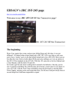
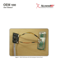
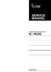
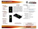
TAIKO Service Manual
2
Chapter
Specifications
2-1. Specifications
2-2. Connector
2-3. Pin Assignment
2-4. Interface Circuit
2-5. External Dimensions
2-6. Panel Cut Dimensions
2-7. DIP Switch Settings
Issue: 01/2007
TAIKO Service Manual
2-1. Specifications
2-1-1. Basic Specifications
Length: 120 mm to 160 mm
Width: 62 mm to 82 mm
4-way
95% or higher
Optical, 4 wavelengths, transparency and reflection
Lever and optical sensor combination
ccTalk/SERIAL(ID-003)/MDB/PULSE
1 banknote
LED lamp (upper potion of faceplate)
Full-color lightning (gradation/solid)
Acceptable Bankenote
CHAPTER
2
Insertion Direction *1
Accepting Rate *1
Validation Method
Anti-Fishing Mechanism
Interface *2
Escrow
LED *2
*1
*2
May differ depending on the software for your country. For details, refer to the
Software Information Sheet.
Can be selected using the DIP switches. See=> 2-7. DIP Switch Setting
2-1-2. Electrical Specifications
Power Supply Voltage
12V DC ±5 %
Standby: Approx. 0.1 A
Rated Power Consumption Operation: Approx. 0.5 A
Max: Approx. 1.4 A (Max. 300 ms)
2-1-3. Environmental Specifications
Operation Temperature *1 5o C to 50o C
o
o
Storage Temperature
-20 C to 60 C
Operation Humidity *1 20%RH to 85%RH (No condensation)
Storage Humidity
20%RH to 85%RH (No condensation)
Avoid direct sunlight
Interior lighting must be incandescent lamp
Light Disturbande
Angle: 15 dgrees or more
Illumination: 3000 Lx or less
Installation
For indoor use only
*1
The overall operation temperature and humidity range is as follows.
(RH%)
35oC / 85RH%
100
90
80
70
60
50oC / 40RH%
Ambient temperature
humidity range
50
40
30
20
10
0
0 5
10
15
20
25
30 35
40
45
50
55
60 (oC)
© 2006 Japan Cash Machine Co., Ltd.. All rights reserved.
2-2
TAIKO Service Manual
2-1-4. Installation Specifications
Installation *1
Weight
External Dimentions
Cahsbox *2
*1
*2
Door holizontal mounting (No vibration)
Approx. 0.6 kg
124 mm (W) x 88 mm (H) x 145.2 mm (D)
Supplied by the customer
2
100 mm or more
Position of
bill ejection slot
Depth from rear of unit
200 mm or more
Width
100 mm or more
Depth from bottom of unit
100 mm or more
Cashbox
Side
Rear
© 2006 Japan Cash Machine Co., Ltd. All rights reserved.
2-3
CHAPTER
Allow 100 mm above the unit to open the lid for removal of the unit from the
faceplate.
The cashbox must be 100 mm or more in depth from the bottom of the TAIKO
unit, 200 mm or more in depth from the rear of the unit and 100 mm or more in
width. Both sides of the cashbox must be higher than the position of the bill ejection slot.
TAIKO Service Manual
2-2. Connector
The following diagram is the interface connector as viewed from the acceptor side or from
a relay board.
CHAPTER
2
Box Type Plug XG4C-1034 (Omron)
- If a relay board is attached to the TAIKO unit, do not attempt
to remove it.
2-3. Pin Assignment
- The following pin assignment is for TAIKO units with a blue
JCM logo label. If the logois black, the pin assignment may
differ. For details, contact JCM.
Blue
Black
2-3-1. ccTalk Interface
Pin No.
1
2
3
4
5
6
7
8
9
10
*1
Signal Name
ccT alk+
NC
NC
NC
NC
NC
Vcc
Vss
NC
NC
I/O *1
Function
IN/OUT ccT alk Send/Receive Line
Not Connected
Not Connected
Not Connected
Not Connected
Not Connected
12V DC Power Supply
Power Supply GND
Not Connected
Not Connected
Conditions for the I/O (Input/Output) column are from the Bill Acceptor side.
© 2006 Japan Cash Machine Co., Ltd.. All rights reserved.
2-4
TAIKO Service Manual
2-3-2. SERIAL(ID-003)/MDB Interface
I/O *1
Function
Not Connected
Not Connected
Data T ransmission Line
IN
(Active when the current is applied)
Data Reception Line
OUT
(Active when the current is applied)
12V DC Power Supply
Power Supply GND
Not Connected
Not Connected
Conditions for the I/O (Input/Output) column are from the Bill Acceptor side.
2
*1
Signal Name
NC
NC
RXDRXD+
T XDT XD+
Vcc
Vss
NC
NC
2-3-3. PULSE Interface
Pin No.
1
2
Signal Name
NC
NC
3
Enable/Disable (-)
4
Enable/Disable (+)
5
6
7
8
9
10
Vend(-)
Vend(+)
Vcc
Vss
NC
NC
*1
I/O *1
Function
Not Connected
Not Connected
Enable/Disable Signal Input Line
In
(Enable when the current is applied.
Disable when the current is NOT applied.)
PULSE Signal Output Line
Out
(Active when the current is applied.)
12V DC Power Supply
Power Supply GND
Not Connected
Not Connected
Conditions for the I/O (Input/Output) column are from the Bill Acceptor side.
© 2006 Japan Cash Machine Co., Ltd. All rights reserved.
2-5
CHAPTER
Pin No.
1
2
3
4
5
6
7
8
9
10
22K
9
HC14
IC1D
DC5V
22K
DC5V
ccTalk (Example)
8
10K
2SC2712Y
47K
RB520S-30
1SS400
DC5V
2-4-1. ccTalk Interface Circuit
GND
1SS400
10K
DC12V
Power
GND
DC12V
12V±5%
12V±5%
Reserve
Reserve
3
4
5
6
3
4
5
6
Reserve
Reserve
Reserve
2
2
NC
ccTalk
GND/ccTalk
Reserve
9
1
8
7
10
ccTalk
GND/ccTalk
CN1
PW12V
GND
R1
10K
GND
PW12V
D20
ISS400
ACCEPTOR PUB-7
10
9
1
8
7
CONTROL BOARD(Example)
3
2-6
4
2-4. Interface Circuit
TR 1B
UMH9 N
5
4
IC1B
3
22K
R14
D5V D5V
22K
R12
SN74LV 14A
D5V
D17
RB520S-30
D18
1SS400
CHAPTER
2
TAIKO Service Manual
© 2006 Japan Cash Machine Co., Ltd.. All rights reserved.
© 2006 Japan Cash Machine Co., Ltd. All rights reserved.
2-7
HC14
IC1D
8
5
3
HC14
IC1C
HC14
IC1B
4
MAX 9600bps
6
HC14
IC1A
2
104uS
52uS
10K
GND
DC5V
TYP=10mA
10mA
(5mA to 15mA)
DC12V
GND
* At leaset 5mA is necessary
2SK1580
1
GND
1SS400
10K
DC12V
RL=470Ω
(1KΩVQΩ)
2SC2712Y
47K
RB520S-30
1SS400
DC5V
MDB/ID003/PULSE(Example)
22K
9
DC5V
22K
DC5V
CC-TALK (Example)
GND
DC12V
3
4
5
TXD -
TXD +
MDB/ID003
/PULSE
RXD -
RXD +
3
4
5
6
2
Reserve
2
6
10
9
1
8
Reserve
NC
TXD -
TXD +
Reserve
Reserve
NC
ccTalk +
GND
12V±5%
RXD -
RXD +
MDB/ID003
/PULSE
CN1
7
10
9
ccTalk +
GND
8
1
12V±5%
7
D21
1SS400
R10
1K 1/4W
D19
1SS400
C1
100pF
PWGND
PW12V
PS2811(K)
3
2
4
IC1B
R24
470Ω
5
3
IC1D
SN74LV14A
8
9
SN74LV14A
D5V
R15
22K
IC1C
5
6
DGND
R9
1K 1/4W
PW12V
D5V
C2
100pF
PWGND
4
PC2
2
1
TR 2B
UMH9 N
PS2811(K)
PC 1
TR 1B
UMH9 N
5
22K
R14
D5V D5V
22K
R12
SN74LV 14A
D5V
D17
RB520S-30
D18
1SS400
1
3
4
GND
R1
10K
PW12V
PWGND
PW12V
D20
ISS400
ACCEPTOR PUB-7
3
4
CONTROL BOARD(Example)
3
4
CHAPTER
2
2-4-2. SERIAL(ID-003)/MDB Interface Circuit
TAIKO Service Manual
5
3
HC14
IC1A
2
1
HC14
IC1C
6
GND
2SK1580
DC5V
TYP=10mA
10mA
(5mA to 15mA)
DC12V
GND
RL=470Ω
(1KΩVQΩ)
FET=ON
(FET=ON ENABLE)
(FET=OFF DISABLE)
* At leaset 5mA is necessary.
HC14
IC1B
4
Setting of DIP Switch
- Pulse Width
- Pulse Speed
PULSE (Example)
GND
DC12V
3
4
5
TXD -
TXD +
PULSE
RXD -
RXD +
3
4
5
6
2
Reserve
2
6
10
9
Reserve
Reserve
1
8
7
CN1
RXD -
RXD +
PULSE
TXD -
TXD +
Reserve
Reserve
NC
Reserve
GND
12V±5%
ACCEPTOR PUB-7
10
9
Reserve
GND
8
1
12V±5%
7
CONTROL BOARD(Example)
D21
1SS400
R10
1K 1/4W
D19
1SS400
C1
100pF
PWGND
PW12V
PWGND
PW12V
PS2811(K)
3
2
R24
470Ω
5
IC1D
SN74LV14A
8
9
SN74LV14A
D5V
R15
22K
IC1C
5
6
DGND
R9
1K 1/4W
PW12V
D5V
C2
100pF
PWGND
4
PC2
2
1
TR 2B
UMH9 N
PS2811(K)
PC 1
1
3
4
3
2-8
4
2-4-3. PULSE Interface Circuit
CHAPTER
2
TAIKO Service Manual
© 2006 Japan Cash Machine Co., Ltd.. All rights reserved.
TAIKO Service Manual
100
124
Unit:mm
103 (Door Installation Position)
2-5. External Dimensions
Top
51 (Bill Ejection Position)
88
17.6 42.7 (Door Install Position)
3.2
47.2
98
Front
Right Side
66
Rear
4-M4
50
19
2
18
83 (Max. Banknote Width)
Bottom
2-6. Panel Cut Dimensions
Max. 4-3R
105 mm
43 mm
Panel Thickness
2mm 㨪 6mm
© 2006 Japan Cash Machine Co., Ltd. All rights reserved.
2-9
CHAPTER
2 mm to 6 mm (Panel Thickness)
TAIKO Service Manual
2-7. DIP Switch Settings
The communication method and various functions of the TAIKO unit can be set with the
DIP switches on the left side of the unit.
ON
CHAPTER
2
1
2
3
4
5
6
7
8
Left Side
2-7-1. Basic Settings
Setting Item
SW#
1
2
3
4
5
6
7
8
ON
Test Mode *1
Double-Scan Mode *2
OFF
Normal Mode
Normal Scan Mode
Reserved
Five (5) drum cycles (fishing prevention) *3
Normal Operation
Refer to the Software Specifications
6
OFF
ON
OFF
ON
*1
*2
*3
*4
*5
7
OFF
OFF
ON
ON
-
8
OFF
OFF
OFF
OFF
ON
I/F Setting
SERIAL (ID-003)
MDB
ccTalk (Non Encrypted)
ccTalk (Encrypted) *4
PULSE *5
For details about the Test Mode, refer to 5-2-2. Test Mode.
The acceptance rate will be improved but operation time will be increased if a
banknote is rejected.
Fishing prevention will be improved but operation time will be increased.
If the encryption code become unclear, refer to 2-7-5. Encryption Code Initializing Setting Mode to initialize the encryption code.
For Details about Communication Setting, refer to the Software Information Sheet.
© 2006 Japan Cash Machine Co., Ltd.. All rights reserved.
2-10
TAIKO Service Manual
2-7-2. Special Settings
Setting Items
Denomination Accept Setting
Setting Mode
Inhibit Setting
LED Pattern Define Pattern 1
Setting Mode Define Pattern 2
Encryption Code Initializing
Setting Mode
Download Mode *1
Adjustment Mode *1
SW2
OFF
OFF
ON
OFF
SW3
OFF
OFF
OFF
ON
SW4
OFF
OFF
OFF
OFF
SW5
OFF
OFF
OFF
OFF
SW6
ON
ON
OFF
OFF
SW7
OFF
ON
ON
ON
SW8
OFF
OFF
OFF
OFF
ON
ON
ON
ON
ON
ON
OFF OFF
ON
ON
OFF OFF OFF OFF OFF ON
ON OFF OFF OFF OFF OFF
ON
ON
For details about Software Download and Adjustment, refer to Chapter 4 Download/Adjustment.
2
Denomination Setting Mode
Perform the accept/inhibit setting for the banknote denomination based on the software for
your country. The default settings are to accept all denominations.
Accept Setting
ON
1
2
3
4
5
6 7
8
To perform the accept setting, set DIP switch Nos.1 and 6 to ON and then turn on the
power to the TAIKO unit. After the LED flashes white, set DIP switch No.1 to OFF to enter
the setting mode. Insert the denomination of banknote that you want accepted into the
insertion slot. The setting is registered if the LED remains lit light blue and the banknote is
returned. Insert the next denomination of banknote that you want accepted.
Inhibit Setting
ON
1 2 3 4 5
6 7 8
To perform the inhibit setting, set DIP switch Nos.1, 6 and 7 to ON and then turn on the
power to the TAIKO unit. After the LED flashes white, set DIP switch No.1 to OFF to enter
the setting mode. Insert the denomination of banknote that you want inhibit into the insertion slot. The setting is registered if the LED remains lit orange and the banknote is returned. Insert the next denomination of banknote that you want inhibited.
© 2006 Japan Cash Machine Co., Ltd. All rights reserved.
2-11
CHAPTER
*1
SW1
ON
ON
ON
ON
TAIKO Service Manual
- The accept/reject setting for banknote denominations can be confirmed with
the LED lamp. After the initial operation is performed, the LED will flash a
number of times equal to the total number of banknote denominations. Blue
indicates an accept setting and red means a reject setting.
Example: If 5, 10 and 20 euro notes are set to be accepted and 50 and 100
euro notes to be rejected, the LED will flash the corresponding 5
times as follows: blue, blue, blue, red and red.
CHAPTER
2
LED Pattern Setting Mode
The LED pattern can be changed according to your perference. Select between pattern 1
and pattern 2. The default setting is pattern 1.
Define Pattern 1
ON
1
2
3
4
5
6 7
8
Set DIP switch Nos.1, 2 and 7 to ON and then turn on the power to the TAIKO unit. Set
DIP switch No.1 to OFF to set the LED pattern to pattern 1.
Dfine Pattern 2
ON
1
2
3
4
5
6 7
8
Set DIP switch Nos.1, 3 and 7 to ON and then turn on the power to the TAIKO unit. Set
DIP switch No.1 to OFF to set the LED pattern to pattern 2.
Encryption Code Initializing Setting Mode
When using ccTalk Communication (Encryption) Mode and the encryption code is unknown, perform the Encryption Code Initializing Setting to initialize the Encryption Code
to the last 6 digits of the TAIKO serial number.
ON
1
2
3
4
5
6 7
8
Set DIP switch Nos. 1 to 6 to ON (Set DIP switch Nos. 7 and 8 to OFF) and then supply the
power to the TAIKO unit. Set DIP switch No. 1 to OFF to initialize the encryption code.
© 2006 Japan Cash Machine Co., Ltd.. All rights reserved.
2-12