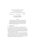
1
Service Manual
CO2 Incubator
MCO-17A
MCO-17AC
FILE No.
MCO-17AC
SM9910036
Effective models
This service manual is effective following models.
Model name
MCO-17A
Product code
823 247 51
823 247 52
823 247 53
823 247 54
823 247 55
823 247 56
823 247 57
823 247 58
823 247 59
823 247 60
823 247 61
MCO-17AC
823 272 51
823 272 53
823 272 54
823 272 56
823 272 57
Voltage and Frequency
110-120V
60Hz
220-240V
50/60Hz
220-240V
50/60Hz
110-120V
60Hz
240V
50Hz
220V
50Hz
220-240V
50/60Hz
110-120V
50/60Hz
220V
50/60Hz
220-240V
50/60Hz
220-240V
50/60Hz
110-120V
220-240V
220-240V
110-120V
110-120V
60Hz
50/60Hz
50Hz
60Hz
60Hz
Features
1. PID temperature controls with micro-computer.
This unit has PID control (Proportional Integrate Differential) accurate controls internal
temperature, as well as air sensor system monitoring internal temperature.
2. Easy install.
This unit use air jacket type chamber which is no need to feed water. It is possible easy to
install and easy to maintenance.
3. Warning system.
This model has temperature (include over heating protection) and CO 2 density alarm
system.
4. CFC-FREE insulation.
Insulation system of model MCO-17AC uses CFC-FREE type rigid polyurethane foam in
place and glass wool.
5. Rounded Ball corners.
Inside chamber wall made by stainless steel and its corner made rounded type.
This made cleaning easier and de-contamination.
Note; Model name
M
CO
–
17
A
C
Copper alloyed stainless steel
Air jacket type
Chamber capacity 164L
CO 2 Incubator
Medical equipment
NOTICE
In general, stainless steel is known that it is not easy (hard) to rust.
However, depends on conditions, rust might generate.
When you remove rust, we recommend the following agents.
Besides, the surface may become foggy.
Recommended agent:
1.Cream creanser “Gif” (Unilever)
2.Picasso #SUS300-W (Chemical YAMAMOTO)
* Picasso has greater capability of clean for rust than “Gif”.
1
Specifications
<Structure>
Name
Model
CO2 incubator
MCO-17A
MCO-17AC
External dimensions
W620 x D605 x H900 (mm)
Internal dimensions
W490 x D505 x H665 (mm)
Interior volume
Tray
164 L
Stainless steel containing copper
5 (standard), 17 (maximum)
Exterior
Interior
Acrylic finish baked on galvanized steel
Stainless steel (SUS-304)
Stainless steel containing copper
Outer door
Acrylic finish baked on galvanized steel
Inner door
Tempered glass
Insulation
Rigid polyurethane foam in place (CFC-FREE)
Heating system
Humidifying system
DHA (heater jacket + air jacket system)
Natural evaporation with humidifying pan
Temperature controller
PID control
CO2 controller
ON-OFF control system
Air circulation
Stir up of breeze
Air filter
Alarm
0.3μm, Efficiency 99.97%
Temperature alarm, CO2 density alarm, upper limit temperature alarm,
door alarm
Capacity of contact point
for remote alarm
Output of recorder
terminal
AC125V, 0.4A; DC30V, 2A
0~100mV (temperature, CO2 density)
φ 4~6 mm tube
CO2 connecting inlet
Weight
Accessories
Optional component
84kg
5trays, 5sets of tray support, 1gas tube, 1humidifying pan
CO2 pressure regulator (MCO-100L), stainless tray (MCO-46ST),
Stack kit (MCO-18PS)
<Performance>
Usable environment condition
0~+35℃
Temperature control range
Ambient temperature +5℃~+50℃
Temperature variation
±0.1℃
Temperature distribution
±0.2℃*
CO2 control range
0~20.0%
CO2 variation
±0.15%*
Chamber humidity
95±5%R.H.
CO2 secondary pressure
0.03MpaG (0.3kg/cm2G)
Maximum power consumption
380W
Noise level
33dB (A scale)
* Value measured at 37℃, CO2 density of 5.0%, ambient temperature 20℃. It is based on
SANYO measuring method.
2
Dimensions
3
Electrical Parts
MCO-17A,17AC
Power transformer
Bottom heater
Side heater R
Side heater L
Flange heater
Back heater
Front heater
Door heater
Door heater (sub2)
Door heater (sub3)
Fan motor
Power switch
Noise filter
Solenoid valve
Temperature control sensor
(Thermistor sensor)
Overheat protect sensor
(Thermistor sensor)
AT sensor
(Thermistor sensor)
P.C.B.
Door switch
CO2 sensor
AC110∼120V, 50/60Hz
AC220∼240V, 50/60Hz
ATR-HN231UT
115V → 8.5/18.0V
14.0W (4pcs)
945Ω 115V
22.0W (2pcs)
601Ω 115V
22.0W (2pcs)
601Ω 115V
45.0W
294Ω 115V
23.0W
586Ω 115V
35.0W
378Ω 115V
120.0W
110Ω 115V
17.0W
945Ω 115V
17.0W
945Ω 115V
FL2-011Y1M
1φ 110V 50/60Hz
AJ921000B
AC250V 16A
ZCE2203-11
AC250V 3A 50/60Hz
FAB11-X1528
Coil: DC24V 1.8W
103-AT1
10kΩ
103-AT1
10kΩ
103-AT1
10kΩ
ATR-HN235T
230V → 8.5/18.0V
14.0W (4pcs)
377Ω 115V
22.0W (2pcs)
2404Ω 230V
22.0W (2pcs)
2404Ω 230V
45.0W
1176Ω 230V
23.0W
2344Ω 230V
23.0W
1511Ω 230V
120.0W
441Ω 230V
14.0W
3779Ω 230V
14.0W
3779Ω 230V
FL2-011Y5M
1φ 230V 50/60Hz
AJ921000B
AC250V 16A
ZCE2203-11
AC250V 3A 50/60Hz
FAB11-X1528
Coil: DC24V 1.8W
103-AT1
10kΩ
103-AT1
10kΩ
103-AT1
10kΩ
Type
CO-17AI
CO-17AI
Type
SS160-A15
SS160-A15
HS-3C-S2
100% → 100mV
HS-3C-S2
100% → 100mV
Type
Rating
Type
Rating
Type
Rating
Type
Rating
Type
Rating
Type
Rating
Type
Rating
Type
Rating
Type
Rating
Type
Rating
Type
Rating
Type
Rating
Type
Rating
Type
Rating
Type
Rating
Type
Rating
Type
Rating
Type
Rating
4
Control specifications
1.
Key and switch
BUZZER: When number is flashing and the buzzer does not sound,
Buzzer and remote alarm output
Forced ON
When number is flashing and the buzzer sounds,
Buzzer and remote alarm output
Forced OFF
SET
2.
:
The first time you press SET the apparatus goes into temperature setting mode.
The second time into CO2 density setting mode, the third time into excessive
temperature rise prevention/checking mode, and the forth time it reverts to internal
temperature display mode.
:
When you press this key in setting mode the highlighted number changes from/to
the tens place, one place and the tenths place. Also, holding this key down for
about 5 seconds in internal temperature display mode activates key lock mode.
:
Press this key in setting mode to increase the flashing number.
CAL
:
Hold this key down for about 5 seconds in internal temperature display mode to
switch into temperature calibration mode. Press it once again to switch to CO2
calibration mode. Also keying in FXX in temperature calibration mode switches to
function mode.
ENT
:
Press this key in setting mode, CAL mode and Function mode to memorize the
number.
Temperature control
Setting range : 0℃∼+50℃
Setting method : Press SET key once, and set temperature using
key and
key.
When you press ENT key, the temperature setting is memorized and the
apparatus goes into CO2 setting mode.
Outside permitted If you key in a temperature outside the setting range and press ENT, the
range:
buzzer sounds (for about 1second continuously) and it stays in
temperature setting mode.
3.
Control
:
PID control
Alarm
:
If the internal temperature is 1℃ higher/lower than setting, the number
flashes and after a delay of 15minutes the buzzer comes on.
CO2 control
Setting range
:
0%~20%
Setting method : Press SET key twice to set CO2 density with
key and
key.
When you press ENT key to memorize the CO2 setting and the apparatus
goes into excessive temperature rise prevention/checking mode.
Out of permitted If you key in a figure outside the setting range and press ENT, the buzzer
range:
sounds (for about 1second continuously) and it stays in CO2 setting mode.
5
4.
Control
:
ON-OFF type
(Valve is closed if the CO2 density is setting –0.02% or higher, opens if it is
setting –0.06% or lower)
Control OFF
:
If you set it at 0.0%, the CO2 density display vanishes and control is OFF.
Alarm
:
If the CO2 density is 1% higher/lower than the setting, the number flashes
and after a delay of 15minutes the buzzer and remote output come on.
Excessive temperature rise prevention / checking
Setting range : +35℃∼+51℃
Setting method : Press SET key 3times to display excessive temperature rise prevention
setting in temperature display and “HI” in CO2 display. This setting value
can be changed by tuning the volume.
When you press SET key again to revert the apparatus to internal
temperature display mode.
5.
Self-diagnostic function
In sensors are malfunctions or CO2 cylinder is detected empty, an error code and the
temperature are displayed alternately. Also the buzzer and remote alarm output come on.
<Error codes>
E01: CO2 cylinder empty
E02: Internal temperature sensor wiring open-circuiting or short-circuiting
E03: CO2 sensor output abnormality
E04: Ambient temperature sensor wiring open-circuiting or short-circuiting
Note) If 2 errors occur (2error codes are generated) simultaneously, only the code
for the one with the bigger number is displayed.
6.
Lock function
Key lock mode
: To switch to lock mode, hold the
key (shift key) down for about 5
seconds when the current internal temperature is being displayed.
When lock mode is activated “L0” is displayed in the temperature display
Press key to change the key lock status:
L1 ……… Key lock ON
L0 ……… Key lock OFF
Note) Press ENT to memorize the current condition and revert to internal
display mode.
7.
Door alarm
Display
Safety operation :
:
When the door is open ……… DOOR lamp ON
When the door is closed …….. DOOR lamp OFF
When the door is open, the fan motor is turned off, the CO2 valve is
closed, and if it stays open for more than 60seconds the heater is also
turned off.
6
8.
Auto return function
If no keys are pressed for 90 seconds in setting mode, lock mode or
function mode, the apparatus automatically exits these modes.
9.
Calibration function
Temperature
: Hold the CAL key down for about 5 seconds in internal temperature
display mode to switch into temperature calibration mode.
When you input the correct temperature using the and
keys and
press ENT key, the temperature is memorized and the incubator reverts
to internal temperature display mode.
:
CO2
To activate CO2 calibration mode, hold the CAL key down for about
5seconds in internal temperature display mode to switch to temperature
calibration mode, and then press the CAL key once more.
<Zero adjustment> If you then key in 00.0 using the
and
key and press ENT key,
the apparatus memorizes the current internal concentration detected,
calls it 0.0%, and it reverts to internal temperature display mode.
<Span adjustment> Alternatively, if you key in correct concentration when CO2 control is
operational and press ENT, it memorizes this as the span calibration
value and reverts to internal temperature display mode.
10.
Function mode
F00:
F01:
F02:
F03:
F04:
F05:
F06:
F09:
Function mode incorporates the following functions:
A ROM version display
Demo (demonstration) mode setting
Humidity heater degree of energizing set
Temperature analogue output calibration
CO2 analogue output calibration
CO2 sensor output voltage (A/D input) display
Ambient temperature display
Memory initialization
Direction for use: In internal temperature display mode, hold the CAL key down for about
5seconds to switch to temperature calibration mode. Key in desired
function code in temperature display section and press ENT key.
F00: Displays a ROM version in the CO2 display.
F01: Sets demo mode.
Key in X1X in the CO2 display and press ENT to go into demo mode.
In demo mode, the settings are displayed continuously, and energizing of the
heater/valve stops. Also, all alarms are cancelled.
To exit demo mode, key in X0X and press ENT.
(X= any number)
F02: Sets degree of energizing for humidity heater’s main heater
Key in a number between 0 and 9 after the decimal point in the CO2 display and
press ENT key. The bigger the number you key in, the greater the degree of
energizing, the higher the internal humidity.
F03: Calibrates the temperature analogue output
Key in a number twice of actual temperature analogue output voltage in the CO2
display and press ENT key.
7
F04: Calibrates the CO2 analogue output
Key in a number of actual CO2 analogue output voltage in the CO2 display and
press ENT key.
F05: Displays the CO2 sensor input voltage (A/D input)
Displays the CO2 sensor input voltage in the display. Unit = <V>
F06: Displays ambient temperature
Indicates the present temperature sensor.
F09: Initializes the CO2 calibration value and the non-volatile memory
Key in XX5 in the CO2 display and press ENT key to initialize the CO2 zero
adjustment value and the span adjustment value.
Key in XX9 in the CO2 display and press ENT key to initialize all the data in the
non-volatile memory.
The initial values in the non-volatile memory are as follows:
Temperature setting
37.0℃
CO2 setting
0.0%
Humidity heater balance
4
Temperature Zero Adjustment data
0.0
CO2 Zero adjustment data
0.0
CO2 span data
1.0
Temperature analogue calibration value
220
110
CO2 Analogue calibration value
Key lock data
Key lock OFF
Demo data
Demo OFF
This function is used when non-volatile data has been destroyed as a result, for
example, of unavoidable noise, and cannot be repaired/recovered. Hence, it is
not used in normal circumstances.
11.
Humidifying heater control
The humidifying heater is energized, as described below, in order to reduce humidity recovery
time. If the internal temperature is between SV-0.4 and SV-0.8 degrees, the humidifying heater
is energized continuously for a maximum of 1 minute. In all other circumstances, it is energized
according to the degree of energizing set using F02.
However, it is not energized continuously in the following circumstances:
1) After the power is switched on, until the internal temperature reaches the (-0.2 degrees)
setting.
2) After the door has been open for more than 60 seconds, until the internal temperature
reaches the (-0.2 degrees) setting.
12.
Offset
In order to compensate for the difference between the temperature detected by the
temperature control sensor and center of internal chamber temperature, the following offset is
applied:
Detected temperature + 0.4 degrees
13.
Remote alarm
In normal circumstances ……... Remote alarm contact is OPEN
In alarm or power failure ……… Remote alarm contact is CLOSE
8
Circuit diagram
9
Components on PCB
10
Specification of sensor
■ The following shows temperature and resistance characteristics on thermistor sensor
103AT-1.
Temperature
(℃)
Resistance
(kΩ)
Temperature
(℃)
Resistance
(kΩ)
Temperature
(℃)
0
27.28
17
13.57
34
7.19
1
26.13
18
13.06
35
6.94
2
25.03
19
12.56
36
6.70
3
23.99
20
12.09
37
6.47
4
22.99
21
11.63
38
6.25
5
22.05
22
11.20
39
6.03
6
21.15
23
10.78
40
5.83
7
20.29
24
10.38
41
5.63
8
19.48
25
10.00
42
5.44
9
18.70
26
9.63
43
5.26
10
17.96
27
9.28
44
5.08
11
17.24
28
8.94
45
4.91
12
16.55
29
8.62
46
4.75
13
15.90
30
8.31
47
4.59
14
15.28
31
8.02
48
4.44
15
14.68
32
7.73
49
4.30
16
14.12
33
7.46
50
4.16
11
Resistance
(kΩ)
Test data
・Temperature unifomity
Test condition
・Amdient temperature
・Amidient humidity
・CO2 level seting
・Water in humidity pan
Shelf
position
Measurewens
position
Upper Shelf
①
②
③
④
⑤
+0.03
+0.14
0.00
−0.15
+0.05
−0.13
+0.05
0.00
Middle Shelf
Lower Shelf
−0.15
−0.13
−0.18
Note: This data does not represent a guarantee of product perfomance.
12
:20℃
:45%RH
:5.0%
:2
Test data
Temperature decrease characteristics when power failure occurs
37
Ambient temp.30℃
Temperature (℃)
35
30
20℃
25
10℃
20
0
1
2
3
4
Time (Hr)
Temperature Recovery Characteristics
38
Temperature (℃)
37
36
35
Door Opening
30sec.
34
Door Opening
60sec.
33
0
10
20
Time (Min)
13
30
40
50
Test data
Humidity Recovery Characteristics
Humidity (%) RH
100
90
80
Door Opening
30sec.
70
Door Opening
60sec.
60
50
0
10
20
30
40
50
Time (Min)
CO2 level Recovery Characteristics
6
CO2 level (%)
5
4
3
Door Opening
30sec.
2
Door Opening
60sec.
1
0
0
10
20
Time (Min)
14
30
40
50
Instruction manual
・ This section is extracted and printed from Instruction Manual.
・ If you find out “Refer to page ●●” in them, this page means not page in service manual
but page in the lower corner of each page in the extract from Instruction Manual.
This page number is not corresponded with serial number in Service Manual.
15