1
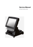
Service Manual
XPOS72-5B-A16G
Copyrights
©2008. All rights reserved. The information in this
document is subject to change without prior notice in
order to improve reliability, design and function and does
not represent a commitment on the part of the
manufacturer.
This document contains proprietary information
protected by copyright. All rights are reserved. No
part of this manual may be reproduced by any
mechanical, electronic, or other means in any form
without prior written permission of the manufacturer.
All trademarks are property of their respective
owners
Liability Disclaimer
In no event will the manufacturer be liable for direct,
indirect, special, incidental, or consequential
damages arising out of the use or inability to use the
product or documentation, even if advised of the
possibility of such damages.
The information in this document is subject to
change without notice
Copyrights
i
Contents
Copyrights .................................................................................................i
Liability Disclaimer ...................................................................................i
Contents....................................................................................................ii
1. Before You Start ...................................................................................1
2. Opening the Device..............................................................................2
3. RAM Disassembly ................................................................................3
4. HDD Disassembly ................................................................................4
5. Touch Panel Control Board Disassembly ..........................................5
6. LED indicator Disassembly.................................................................6
7. Power Switch Disassembly.................................................................7
8. Mainboard and I/O Panel Disassembly ..............................................8
9. Speaker Assembly Disassembly ......................................................10
10. LCD Panel Disassembly ..................................................................11
ii
Contents
1.
1. Before You Start
1. Please unplug the power cable before you start to work.
2. Please read and follow the instructions in this document carefully. Failure to
follow these instructions could damage your device and void the warranty.
1.1. Tools Suggested
All procedures in this document require the following tools:
#0 Phillips screwdriver
(Magnetized suggested)
#1 Phillips screwdriver
(Magnetized suggested)
1.5 mm hexagon socket spanner
(Magnetized suggested)
Chapter 1
1
2.
2. Opening the Device
1. Loosen the screw of the VESW wall mount and remove the device from the
base as shown.
2. .Un-tighten two screws on the back panel anticlockwise.
3. Separate the back panel from the front panel by lifting up and lay it down
carefully.
2
Chapter 2
3.
3. RAM Disassembly
1. Open the tow ejectors on the slot by pushing them, and remove the RAM
from the slot.
4. Remove the old RAM.
5. Align and insert the new RAM in the slot and push both ends of the RAM
down until the ejectors snap into place.
Chapter 3
3
4.
4. HDD Disassembly
1. Loosen the four screws by #1 Phillips screwdriver as shown below and remove the
HDD assembly from the device.
2. Unplug one connector of the SATA cable and power cable from the HDD.
3. Loosen the four screws fixing the HDD and remove the HDD from the bracket as
shown below.
5. Install the new HDD in the reverse procedure from Step 4 to Step 1.
4
Chapter 4
5.
5. Touch Panel Control Board Disassembly
1. Remove: 1. LED indicator connector, 2. SATA cable, 3. LCD connector, 4 inverter
connector, 5. power switch connector, HDD power cable and touch panel cable, 6
parallel port cable, 7. serial port cable, 8. Customer display cable, 9. USB cable and
10 speaker and MSR cable from the mainboard.
2. Disconnect three connecters form the LCD inverter as shown below.
3. Loosen the three screws by #0 Phillips screwdriver and remove the LCD
inverter.
4. Install the new LCD inverter in the reverse procedure.
Chapter 5
5
6.
6. LED indicator Disassembly
1. Unplug the LED indicator from the LCD chasiss.
6
Chapter 6
7.
7. Power Switch Disassembly
1. Remove the power switch from the device.
Chapter 7
7
8.
8. Mainboard and I/O Panel Disassembly
1. Loosen the four hexagonal screws by 1.5 mm hexagonal socket spanner as
shown below.
3. Loosen the four screws by #0 Phillips screwdriver as shown below.
4. Remove the mainboard from the device as shown below.
8
Chapter 8
5. Remove the two screws by #1 Phillips screwdriver and remove the I/O panel.
7. Loosen the four hexagonal screws by 1.5 mm hexagonal socket spanner as
shown below and you can remove the COM port and parallel port from the I/O
panel.
Chapter 8
9
9.
9. Speaker Assembly Disassembly
1. Loosen the four screws by #1 Phillips screwdriver as shown below and remove the
speaker assembly from the device.
10
Chapter 8
10.
10. LCD Panel Disassembly
1. Loosen the fourteen screws in blue circle as shown below by #1 Phillips screwdriver.
3. Remove the LCD panel assembly and loosen the four screws holding the LCD.
Chapter 10
11
4. Loosen the eight screws in blue circle as shown below by #1 Phillips screwdriver.
5. Lift up the touch panel and you can take out the LCD.
12
Chapter 10