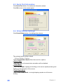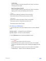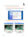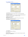
1
User’s Manual
BPC65-B-A16G
Copyrights
that interference will not occur in a particular
installation. If this equipment does cause harmful
©2009. All rights reserved. The information in this
interference to radio or television reception, which
document is subject to change without prior notice in
order to improve reliability, design and function and does
not represent a commitment on the part of the
manufacturer.
can be determined by turning the equipment off and
on, the user is encouraged to try to correct the
interference by one or more of the following
measures:
This document contains proprietary information
• Increase the separation between the equipment
protected by copyright. All rights are reserved. No
and the receiver.
part of this manual may be reproduced by any
• Connect the equipment into an outlet on a circuit
mechanical, electronic, or other means in any form
different from that to which the receiver is connected.
without prior written permission of the manufacturer.
• Consult the dealer or an experienced radio or
television technician for help.
All trademarks are property of their respective
This device complies with Part 15 (B) of the FCC
owners
Rules. Operation is subject to the following two
conditions:
Liability Disclaimer
In no event will the manufacturer be liable for direct,
indirect, special, incidental, or consequential
damages arising out of the use or inability to use the
product or documentation, even if advised of the
possibility of such damages.
FCC Notices
1) this device may not cause harmful interference
and
2) this device must accept any interference received,
including interference that may cause undesired
operation.
NOTE: THE MANUFACTURER IS NOT
RESPONSIBLE FOR ANY RADIO OR TV
INTERFERENCE CAUSED BY UNAUTHORIZED
MODIFICATIONS TO THIS DEVICE. SUCH
MODIFICATIONS COULD VOID THE USER'S
AUTHORITY TO OPERATE THE DEVICE.
This equipment has been tested and found to comply
with the limits for a Class B digital device, pursuant to
Part 15 of the Federal Communications Commission
(FCC) Rules. These limits are designed to provide
CE Notice
reasonable protection against harmful interference in
a residential installation. This equipment generates,
uses, and can radiate radio frequency energy and, if
not installed and used in accordance with the
instructions, may cause harmful interference to radio
communications. However, there is no guarantee
Copyrights
This device complies with EMC Directive
2004/108/EC issued by the Commission of the
European Community.
i
WEEE Notice
The WEEE mark applies only to countries within the
European Union (EU) and Norway.
This appliance is labeled in accordance with
European Directive 2002/96/EC concerning waste
electrical and electronic equipment (WEEE). The
Directive determines the framework for the return
and recycling of used appliances as applicable
throughout the European Union. This label is applied
to various products to indicate that the product is not
to be thrown away, but rather reclaimed upon end of
life per this Directive.
Safety Notice
CAUTION: Danger of explosion if battery is
incorrectly replaced. Replace only with the same or
equivalent type recommended by the manufacturer.
Dispose of used batteries according to the
manufacturer’s instructions.
ii
Contents
Contents
Copyrights .................................................................................................i
Liability Disclaimer ...................................................................................i
FCC Notices...............................................................................................i
CE Notice ...................................................................................................i
WEEE Notice.............................................................................................ii
Safety Notice ............................................................................................ii
Contents...................................................................................................iii
1. Hardware Setup....................................................................................1
1.1. Unpacking the Box....................................................................................... 1
2. Quick Tour ............................................................................................2
2.1. Front View..................................................................................................... 2
2.2. Rear View ...................................................................................................... 2
2.3. Peripherals Installation................................................................................ 3
Power Adapter.........................................................................................................................3
USB Mouse, USB Keyboard and USB ODD .........................................................................3
VGA LCD Touchscreen Monitor (WTM/TM Series Recommended) ...................................4
2.4. Turn on the Device ....................................................................................... 5
3. Basic Driver Installation ......................................................................6
3.1. Before the installation.................................................................................. 6
3.2. Chipset Software Installation ...................................................................... 6
3.3. VGA Driver Installation ................................................................................ 8
3.4. Touch Screen Driver and Software Utility installation .............................11
3.4.1. WTM series..................................................................................................................11
3.4.2. TM 550 Touch Monitor................................................................................................14
3.5. LAN Driver Installation............................................................................... 17
4. Touchscreen Control Panel Quick Guide (WTM Series).................19
4.1. Launch Touchscreen V7.5.COM................................................................ 19
4.2. User interface ............................................................................................. 19
4.3. Serial Port Information .............................................................................. 20
4.4. Virtual Button Settings .............................................................................. 20
Virtual Button Option ...........................................................................................................20
Right Button Function..........................................................................................................21
Right Button Automatic Mode .............................................................................................21
4.5. Feedback Sound ........................................................................................ 22
Feedback Sound Option ......................................................................................................22
Tone........................................................................................................................................23
Duration .................................................................................................................................23
4.6. Screen Calibration ..................................................................................... 23
4 points, mode 1....................................................................................................................23
4 points, mode 2....................................................................................................................24
Contents
iii
How to Use Event Selector ..................................................................................................25
5. Touch Panel Settings (TM Series) ....................................................26
5.1. Start screen of Touch Panel Settings ....................................................... 26
5.2. Hardware set-up ......................................................................................... 27
Single Monitor (Plug and Play Device) ...............................................................................27
Port Setting............................................................................................................................27
Data interval time ..................................................................................................................27
Mouse Cursor Setting ..........................................................................................................27
Dual Monitor (Non-Plug and Play Device)..........................................................................27
Port Setting............................................................................................................................27
Data interval time ..................................................................................................................28
Mouse Cursor Setting ..........................................................................................................28
5.3. Audible feedback set-up............................................................................ 28
Audible feedback setting .....................................................................................................28
5.4. Touch sensitivity set-up ............................................................................ 29
Operate mode........................................................................................................................29
Double-click setting..............................................................................................................30
5.5. Right button simulation ............................................................................. 30
Right click simulation...........................................................................................................30
Display the icon in the task bar tray ...................................................................................31
Display the icon in the Window...........................................................................................31
5.6. Calibration .................................................................................................. 32
Touch Panel controller features ..........................................................................................32
Accuracy required ................................................................................................................32
Calibration .............................................................................................................................32
5.7. Dual Monitor (Non Plug and Play Device Only) ....................................... 35
Use the dual monitor function.............................................................................................35
OS management dual monitor ............................................................................................35
Monitor position setting.......................................................................................................35
Use port .................................................................................................................................35
6. I/O Definition.......................................................................................36
6.1. Power Connector ....................................................................................... 36
6.2. Serial Port 1/2/3/4 ....................................................................................... 36
JP4 COM 1 Power COM1 Signal / Power Selection...........................................................37
JP5/ 6/ 7 COM2/ 3/ 4 Signal / Power Selection ...................................................................37
6.3. VGA Connector........................................................................................... 39
6.4. LAN and USB 1/2........................................................................................ 39
6.5. USB 3/4 ....................................................................................................... 40
7. Specification.......................................................................................41
7.1. The Device .................................................................................................. 41
iv
Contents
7.2. The Wall Mount Kit ..................................................................................... 42
7.3. Build-in Dimension .................................................................................... 43
Contents
v
1.
1. Hardware Setup
1.1. Unpacking the Box
Chapter 1
The Device X 1
Power Adaptor X 1
Power Cord X 1
Driver and Utility CD X 1
1
2.
2. Quick Tour
2.1. Front View
2.2. Rear View
The Power indicator will glow green when power is on.
The HDD indicator will blink green when the HDD is accessed.
2
Chapter 2
Note: For details of I/O ports on the back panel, please refer to 6. I/O
Definition.
2.3. Peripherals Installation
Power Adapter
Connect the output jack of the adapter to the DC 12V jack on the back panel of
the device.
USB Mouse, USB Keyboard and USB ODD
Connect your USB Mouse, USB Keyboard and USB ODD to USB ports on the
back panel of the device.
Chapter 2
3
VGA LCD Touchscreen Monitor (WTM/TM Series
Recommended)
1. Connect one end of the Serial Port Cable to the COM male port on the back
panel of the device, another end to the COM port of your LCD panel.
2. Connect one end of the VGA cable to the VGA female port on the back panel
of the device, another end to the VGA port of your LCD panel.
LAN Cable
Connect one end of RJ-45 LAN cable to the LAN port on the back panel of the
device, another end to your internet device.
Note: For detail information about WTM/TM series touchscreen monitor, please
contact your dealer.
4
Chapter 2
Vertical Stand
2.4. Turn on the Device
1. Make sure all peripherals are connected properly.
2. Press and hold the power switch until the power indicator on the front panel
glow green.
Chapter 2
5
3.
3. Basic Driver Installation
3.1. Before the installation
For CD-ROM onboard model:
1. Insert the driver CD into the onboard CD-ROM drive. The program
autoruns and displays the DRIVER BANK screen.
2. Follow the on-screen instructions.
For Model without CD-ROM Onboard:
1. Connect an external USB CDROM to the USB power and insert the driver
CD and turn on the device. The program autoruns and displays the DRIVER
BANK screen.
2. Follow the on-screen instructions.
3.2. Chipset Software Installation
1. On the main screen, click “BOXPC 65 Series”.
2. Click INTEL Chipset Driver.
6
Chapter 3
3. Click Next.
4. Read the License Agreement carefully and click Yes.
4. Click Next.
Chapter 3
7
6. Click Finish.
3.3. VGA Driver Installation
1. On the main screen, click “BOXPC 65 Series”.
2. Click VGA Driver.
8
Chapter 3
3. Click VGA Driver for WIN2K/XP.
4. Click Next.
5. Read the License Agreement carefully and click Yes.
Chapter 3
9
6. Click Next.
7. Click Next.
8.1. Select restart your computer right now or later, and then lick Finish.
10
Chapter 3
3.4. Touch Screen Driver and Software Utility installation
Note: If the touchscreen monitor you used is not WTM or TM series, please refers to
the user manual of it for touch screen driver installation.
3.4.1. WTM series
The installation procedure shown below is based on Microsoft Windows XP.
1. On the main screen, click “BOXPC 65 Series”.
2. Click “Touch Panel Driver”.
3. Click “Touch Panel Driver for WINXP”.
4. Click “Next” button.
Chapter 3
11
5. Click “Browse” to select the location where the driver installed, and then
click “Next”. Or you can click “Next” go to next screen directly.
6. Click “Browse” to select the start menu folder, and then click “Next”.
Or you can click “Next” go to next screen directly.
6. This screen displays setting information. Click Install to continue
12
Chapter 3
installation. If you would like to change settings, click Back to return to
previous screens.
7. During the installation, the following screen will be displayed.
8. The message below shows after the installation was successful. Click
"OK" to complete the installation.
Chapter 3
13
3.4.2. TM 550 Touch Monitor
1. Click TM70/WTM60/TM550/TM515 Series.
2. Click Touch Driver.
3. Click Touch Driver For TM550/TM515 Series.
14
Chapter 3
4. Click Next.
5. Select an item according to your needs, and then click Next.
Click the OK button on the pop-up message.
6. If you want to use Multi-Monitor, check the box and click Next.
Chapter 3
15
7. Click Next.
8. Click Next.
9. Click Next.
16
Chapter 3
9 The driver starts to install.
10. Click OK.
3.5. LAN Driver Installation
1. After clicking “BOXPC 65 Series” on the main screen, click RTL8111C Lan
Driver.
Chapter 3
17
2.1.
On the welcome screen, click Next.
2.2.
Click Install to begin the installation.
3. Click Finish.
18
Chapter 3
4.
4. Touchscreen Control Panel Quick Guide
(WTM Series)
Note: If the touchscreen monitor you used is not WTM or TM series, please refers to
the user manual of it for touch screen driver operation.
4.1. Launch Touchscreen V7.5.COM
1. Under Microsoft Windows XP, click “start” menu and select “Programs”,
under ”Touchscreen V7.5.COM” menu, click “Touchscreen Control Panel
V7.5.COM”, the control panel of the program shows.
4.2. User interface
a
b
c
d
e
f
g
h
i
Serial Port
Display serial port information of the system.
Virtual Button
Open the virtual button setting dialogue box.
Feedback Sound
Open the feedback sound setting dialogue box.
Power Save
Open the power down timer adjustment dialogue box
Calibration
Switch to calibration screen.
Calibration Mode Menu Select the calibration by clicking this drop-down list.
Display technical support information.
Support
Exit
Event Selector
Chapter 4
Exit the program.
Enable right mouse button function.
The default of this selector is with the left mouse button
selected on. For details about event selector settings,
please see “How to Use Event Selector” of Section 5.2.
19
4.3. Serial Port Information
Click Serial Port button, the serial port information shows.
Click OK to back to the control panel.
4.4. Virtual Button Settings
Click Virtual Button button, the dialogue box shows:
The selected option will be in black.
Virtual Button Option
Under Virtual Button Option field, there are four options:
․Stream Mode
Under this mode, all mouse button simulation will be disabled.
․Lift off Mode
Under Lift off Mode, tapping and holding on the screen equals pressing and
holding on the left button of the mouse.
․Touch Down Mode
Under Touch Down Mode, one single-tapping equals one left mouse
clicking.
20
Chapter 4
․Drag Drop Mode
Drag Drop mode allows you to select an object on the screen by tapping, and
then slide the selected object to a new location on the screen, the selected
object will be dropped on the new location by releasing the touch.
The selected option will be in black.
Right Button Function
․Disabled (Off)
Select this option, the event selector
․Enable (On)
will be disabled and disappear.
Select this option, the event selector
the left-bottom corner of the screen.
will be enabled and show on
․Automatic Mode/Manual Mode Drop-down List
If the Drag Drop Mode under Virtual Button Option field is select, the
drop-down menu below the Enable (On) option will be enabled.
Automatic Mode
- Select this option, the Right Button Function will switch to automatic
mode and the event selector
will be disabled and disappear.
Manual Mode
- Select this option, the Right Button Function will switch to manual
mode and the event selector
left-bottom corner of the screen.
will be enabled and show on the
- Options under Right Button Automatic Mode will be enabled when
Manual Mode is selected.
The selected option will be in black.
Right Button Automatic Mode
Toggle On time is the duration between the tapping on the screen and that
the right mouse button is “virtually” pressed and held.
Chapter 4
21
Release the tapping from screen after toggle-on, the pop-up menu shows.
The minimize value is 0.5 and maximum value is 5.
This option defines how long the right button function will be off.
The minimize value is 0.5 and maximum value is 5.
Click the drop-down menu to select On or Off to enable or disable the beep
sound effect for toggle-on and toggle off.
4.5. Feedback Sound
Click Feedback Sound button, the dialogue box shows:
Feedback Sound Option
Silence (No Sound)
No any sound effect.
Touch Down Only
When this option is selected, there will be one “beep” sound when
tapping on the screen.
22
Chapter 4
Lift Off Only
When this option is selected, there will be one “beep” sound when
releasing from the screen.
Both Touch Down & Lift Off
When this option is selected, there will be one “beep” sound when
tapping on the screen and releasing from the screen.
Tone
Drag the bar to adjust the frequency of the sound effect.
The minimize value is 200 and maximum value is 5000.
Duration
Drag the bar to adjust how long the “Beep” sound will be.
The minimize value is 10 and maximum value is 50.
The selected option will be in black.
4.6. Screen Calibration
1. Click the drop menu next to the Calibration button to select calibration
mode.
4 points, mode 1 – rectangular four-point calibration
4 points, mode 2 – rhombic four-point calibration
2. Click Calibration button to enter the calibration screen.
4 points, mode 1
a. The
mark shows on the Left-up corner.
b. Follow the instruction in green to touch the center of Cross Mark.
c. When the instruction turns into yellow, releasing the tapping from the
screen.
d. Follow the instruction in green to touch the center of Cross Mark.
e. Repeat Step 2 – Step4 to finish the calibration procedure.
Chapter 4
23
4 points, mode 2
a. The
mark shows in the middle of the length of the screen..
b. Follow the instruction in green to touch the center of Cross Mark.
c. When the instruction turns into yellow, releasing the tapping from the
screen.
d. Follow the instruction in green to touch the center of Cross Mark.
e. Repeat Step 2 – Step4 to finish the calibration procedure.
24
Chapter 4
3. When the calibration procedure is completed, the message shows:
To save the new calibration, click Yes, to restore the old calibration, click No.
How to Use Event Selector
1. On the desktop of Windows, click
icon.
2.
icon change to
.
3. Now the tapping is simulating right mouse button clicking.
4. After one tap on the screen,
icon change to
5. The tapping resumes to left mouse button clicking
Chapter 4
.
25
5.
5. Touch Panel Settings (TM Series)
Note: If the touchscreen monitor you used is not WTM or TM series, please refers to
the user manual of it for touch screen driver operation.
To launch Touch Panel Settings, click Start, click Control Panel, and then
double-click
icon.
Note: The contents of this chapter are extracted from Fujitsu Touch Panel (Serial) Device
driver setting manual V1.0L24.
“Fujitsu” is the registered trademark of FUJITSU LIMITED.
5.1. Start screen of Touch Panel Settings
Single Monitor
(Plug and Play Device)
26
Dual Monitor
Non-Plug and Play Device
Chapter 5
5.2. Hardware set-up
Single Monitor (Plug and Play Device)
Port Setting
The setup can't be changed, because COM is recognized automatically.
Data interval time
Using slider in the scroll bar, you can change coordinates data interval time of
touch panel controller from 10ms to 155ms by 5ms step.
Mouse Cursor Setting
Delete Cursor check box
The display of the mouse cursor is deleted. The special cursor of other
application isn't deleted by this setup.
Dual Monitor (Non-Plug and Play Device)
Port Setting
You can add two maximum COM ports.
How to add a port:
Input three fields of port setting below. And, it is added to the port connected
by pushing an "=> Add" button.
Chapter 5
27
Notes
* Setting change should be effective after the system restart. And you can’t use "Calibration"
tab page and "Use port" of "Dual monitor set-up" tab page until system restart.
* There is a thing that PC causes defective operation when Port address (I/O address, IRQ
number ) not set by Windows is input.
* When ports other than COM1-9 are used, input a suitable port number of COM1-9 that is
not used instead of actual COM port number. And, set the I/O address and the IRQ number
as you wish to use.
COM
Input the COM port number that the device is connected.
I/O
Input the I/O address that the device is connected.
IRQ
Input the IRQ number that the device is connected.
Data interval time
Using slider in the scroll bar, you can change coordinates data interval time of
touch panel controller from 10ms to 155ms by 5ms step.
Mouse Cursor Setting
Delete Cursor check box
The display of the mouse cursor is deleted. The special cursor of other
application isn't deleted by this setup.
5.3. Audible feedback set-up
Single Monitor
(Plug and Play Device)
Dual Monitor
Non-Plug and Play Device
Audible feedback setting
Sound enabled check box
Sound function is enabled when checked.
28
Chapter 5
Sound when pressed
The sound comes out when touch panel is pressed.
Sound on release
The sound comes out when touch panel is released.
Kind of sound drop-down list
The sound can be selected from among Beep Sound, Asterisk, Exclamation,
Question, Critical Stop, Default Sound, and Standard Sound
Note: Please use “Sounds” in the control panel to set the condition of Asterisk, Exclamation,
Question, Critical Stop, Default Sound, and Standard Sound.
Back to driver default button
The sound setting is returned to driver default setting.(Sound disabled,
Sound when pressed ,Beep Sound , Frequency:1000Hz , Beep time:50ms)
Set it as user default button
Present sound settings are preserved as standard setting. Contents
preserved are displayed in the column of "User default setting".
Set as user default button
Back to user default setting according to preserved condition.
5.4. Touch sensitivity set-up
Single Monitor
(Plug and Play Device)
Dual Monitor
Non-Plug and Play Device
Operate mode
Stream mode
The coordinates value is continuously output until touch panel turns to off.
Point mode
Point operation. Turning off is notified immediately after turning on is
notified. Even if touch continues at the following, no data is output.
Chapter 5
29
Double-click setting
The range and the speed to make the system recognize double-clicking can
be changed. Moreover, it can be set that double-clicking is prohibited.
Setting change is effective after “OK" or "Apply" button is clicked.
Note: Settings of the above-mentioned Width, Height, and the Speed also affect to other
mice connected with the system. But double-clicking prohibition is only for the touch panel.
Double-clicking prohibition check box
Disable the double-clicking of the touch panel when checked.
Width: The horizontal range recognized as double-clicking is set. 2 - 32
[pixel]
Height: The vertical range recognized as double-clicking is set. 2 - 32 [pixel]
Speed: The maximum time between clicks recognized as
double-clicking is set. 150 - 850[ms]
Test: The actual double-click test on displayed icon. Icon display is changed
when double-clicking is recognized
5.5. Right button simulation
Single Monitor
(Plug and Play Device)
Dual Monitor
Non-Plug and Play Device
Right click simulation
Enable the right click simulation check box
Enable function and activate following items when checked.
Ctrl key, Shift key, Alt key
Select the cooperative key for right-clicking function.
Right click is simulated whilst function key is pressed
30
Chapter 5
Just as the guidance when checked. (The Alt key dose not work with this
setting.)
Right click happens only once after function key is pressed
Just as the guidance when checked.
Display the icon in the task bar tray
The icon of the mouse style (see figures below) is registered in the task tray
and right click simulation works without cooperative key operation when
checked.
Display the icon in the Window
The icon of the mouse style (see figures below) is registered in the desktop
and right click simulation works without cooperative key operation when
checked.
Operation of icon
The letter of “L” and “R” of the icon shows a present state. At the “R” state,
touch works as right-click once and state turns to “L”. State is changed
alternatively by touching icon.
Note: When the mouse is set for left-handed, the display of L and R becomes opposite.
Chapter 5
31
5.6. Calibration
Single Monitor
(Plug and Play Device)
Dual Monitor
Non-Plug and Play Device
Touch Panel controller features
Use onboard EEPROM to store calibration results
Do not check here when EEPROM is not used.
Accuracy required
Select the calibration point number.
At EEPROM less condition, the calibration point number is limited to 9.
Calibration
Calibration Now button
This button executes the calibration program. When “Touch Panel controller
features” and “Accuracy required” are changed. Calibration can't be carried
out until “OK” and “Apply” button are pushed and a setup is renewed.
The calibration is done so that pressed position of touch panel device
matches to the display position. When the touch panel driver setup or the
touch panel device is exchanged, it is necessary to calibrate.
1) Click Calibration Now button.
2) The calibration screen is displayed (one “+“ mark is displayed on the left
up corner ).
3) Push “+“ mark. When a push point was effective, the following "+" mark is
displayed.
4) After all “+“ marks are pressed (9 or 20 pieces), screen is changed to “Test
screen” automatically.
Notes
When you change the port setting in the “Hardware set-up” tab, the calibration program can't
32
Chapter 5
be carried out till system restarts.
Calibration screen
Key input at calibration screen
[Home]
[Esc]
[Arrow keys]
[Enter]
Cancel calibration data and skip to test screen.
Cancel calibration data and close calibration program.
Move the calibration point mark.
Revise the calibration data and skip to test screen.
Test screen
You can do free drawing in this screen so that the result of the calibration can
be judged by watching pen input position and displayed position.
Drawing test screen where key box is used
Key box input of this drawing test screen
Chapter 5
33
Calib screen
Back to calibration screen.
Cursor on/off
On and off the cursor display on the screen.
CLR screen
Update
Clear the screen.
Close the calibration program.
Close the key box window, and screen changes to the style
below.
Key input of this drawing test screen
[Home]
[Tab]
[Delete]
[Insert]
[Enter]
34
Back to calibration screen.
On and off the cursor display on the screen.
Clear the screen and key guidance part moves up and down.
The key box is displayed and screen changes into the first
style.
Close the calibration program.
Chapter 5
5.7. Dual Monitor (Non Plug and Play Device Only)
Use the dual monitor function
Check here when you wish to use dual monitor function.
OS management dual monitor
Select whether it is OS management dual monitor or video card
management dual monitor.
Monitor position setting
Drag the picture of monitor 1 and 2, and set the position same as actual
monitor arrangement.
Monitor 1
Select the resolution of monitor1.
Monitor 2
Select the resolution of monitor2.
Use port
Monitor 1
Click the drop-down list to select the port of the touch panel set up on monitor1.
Monitor 2
Click the drop-down list to select the port of the touch panel set up on monitor2.
Notes
Dual monitor set-up screen isn't shown with a PNP touch panel for
Widnows95/98/Me/2000/XP.
When you change the port setting in the “Hardware set-up” tab, “Use port” can't be changed
till system restarts.
Chapter 5
35
6.
6. I/O Definition
Please refer the detailed technical information about all I/O ports as followings.
6.1. Power Connector
Pin
1
2
3
Signal Name
NC
+12V
GND
6.2. Serial Port 1/2/3/4
Pin
36
Signal
1
DCD, Data carrier detect
2
RXD, Receive data
3
TXD, Transmit data
4
DTR, Data terminal ready
5
GND, ground
6
DSR, Data set ready
7
RTS, Request to send
8
CTS, Clear to send
9
RI, Ring indicator
Chapter 6
JP4 COM 1 Power COM1 Signal / Power Selection
Jumper Setting
1
2
Function
1-3 Short
Pin 1 of COM1 = +12V
3-5 Short
Pin 1 of COM1 = +5V
5-7 Short
Pin 1 of COM1 = +5V
7-9 Short
Pin 1 of COM1 = DCD@RS232,
TX-@RS422, DATA-@RS485
(Default)
2-4 Short
Pin 9 of COM1 = +12V
4-6 Short
Pin 9 of COM1 = +5V
6-8 Short
Pin 9 of COM1 = +5V
8-10 Short
Pin 9 of COM1 = RI (Default)
Pitch: 2.54mm [YIMTEX 3322*05SAGR(6T]
JP5/ 6/ 7 COM2/ 3/ 4 Signal / Power Selection
Jumper Setting
1
2
Function
1-3 Short
Pin 1 of COM2/ 3/ 4 = +12V
3-5 Short
Pin 1 of COM2/ 3/ 4 = +5V
5-7 Short
Pin 1 of COM2/ 3/ 4 = +5V
7-9 Short
Pin 1 of COM2/ 3/ 4 = DCD (Default)
2-4 Short
Pin 9 of COM2/ 3/ 4 = +12V
4-6 Short
Pin 9 of COM2/ 3/ 4 = +5V
6-8 Short
Pin 9 of COM2/ 3/ 4 = +5V
8-10 Short
Pin 9 of COM2/ 3/ 4 = RI (Default)
Pitch: 2.54mm [YIMTEX 3322*05SAGR(6T]
For the location of JP4/5/6/7 on the main board, please see the figure below:
Chapter 6
37
38
Chapter 6
6.3. VGA Connector
Pin
Signal Name
Pin
Signal Name
1
Red
9
VCC
2
Green
10
GND
3
Blue
11
NC
4
NC
12
DDC2B data
5
GND
13
HSYNC
6
GND
14
VSYNC
7
GND
15
DDC2B clock
8
GND
6.4. LAN and USB 1/2
Chapter 6
Pin
Signal
Pin
Signal
1
MDI[0]+
U1
+5V
2
MDI[0]-
U2
USB0-
3
MDI[1]+
U3
USB0+
4
MDI[1]-
U4
GND
5
MDI[2]+
U5
+5V
6
MDI[2]-
U6
USB1-
7
MDI[3]+
U7
USB1+
8
MDI[3]-
U8
GND
39
6.5. USB 3/4
40
Pin
Signal Name
Pin
Signal Name
1
+5V
5
+5V
2
USB1-
6
USB0-
3
USB1+
7
USB0+
4
GND
8
GND
Chapter 6
7.
7. Specification
7.1. The Device
Chapter 7
41
7.2. The Wall Mount Kit
42
Chapter 7
7.3. Build-in Dimension
For the best thermal efficiency and safety, when installing or mounting the device in a
cabinet or rack, the minimum clearance distance show be kept as followed
Chapter 7
43
Main Board
CPU
Intel® AtomTM Processor N270 1.6GHz
Chipset
Intel 945GSE / ICH7-M
System Memory
SO-DIMM DDR2 533, 128MB up to 2GB
Thermal Solution
Fan-less
OS
Windows XP / XPe, WEPOS, POS Ready, Linux*
I/O Ports
USB
4 x RS-232
COM 1 : RS232/422/485 DB-9, Pin9 w/ RI/5V/12V jumper selected
COM 2 / 3 / 4 : RS232 DB-9, Pin9 w/ RI/5V/12V jumper selected
4 x USB 2.0
LAN
1 x Gigabit Ethernet by RJ-45 , Support Wake on LAN and boot on LAN
Audio
Line-in, Line-out and Mic-in
VGA
1 x DB-15
Expansion
1 x Mini PCI, optional wireless LAN module
Serial
Others
Wall Mount
Support VESA Mount
Power Supply
External Adapter, 60W, 12VDC Input
Compliance
FCC / CE / WEEE / RoHS / CCC
Weight
Approx. 1.43 Kg
Dimension
189 W x 179 Dx 52 H mm
Operating Temperature
0°C ~ 40°C
Storage Temperature
-20°C ~ 60°C
Storage Humidity
20 – 85%
Optional Accessories
Part No.
Description
A0400614
Wireless LAN 802.11 WIFI module Antenna
20200023
2.5'' Slim Type HD: 160GB SATA TYPE
20300021 Memory
DDRR2-667, 512MB, 200Pin SO-DIMM, non-ECC
20300022 Memory
DDRR2-667, 1GB, 200Pin SO-DIMM, non-ECC
20900001 OS
Windows XP Professional, English version
20900002 OS License
WEPOS, English Version
A0400696
Wall Mount Kits
44
Chapter 7