1
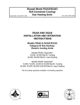
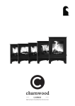
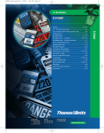
Models RGAD & SGAD - R410A
User's Information, Maintenance
And Service Manual
Supersedes: 145.25-O1 (708)
Form 145.25-O1 (908)
MODELS RGAD & SGAD - R410A
USER'S INFORMATION, MAINTENANCE
AND SERVICE MANUAL
CATEGORY III GAS HEATING/ELECTRIC COOLING UNITS
Model RGAD Capacities*
18,000, 24,000 Btu/Hr - Cooling
40,000, 60,000 Btu/Hr. Heating
Model SGAD Capacities*
12,000, 18,000, 24,000 & 30,000 Btu/Hr - Cooling
20,000, 40,000, 60,000 & 80,000 Btu/Hr. - Heating
* Not all cooling capacities available in all heating capacities
FIRE OR EXPLOSION HAZARD
Failure to follow safety warnings exactly could result
in serious injury, death or property damage.
- Do not store or use gasoline or other flammable vapors and iquids
in the vicinity of this or any other appliance.
- WHAT TO DO IF YOU SMELL GAS
• Do not try to light any appliance.
• Do not touch any electrical switch; do not use any phone in
your building.
• Immediately call your gas supplier from a neighbor’s phone.
Follow the gas supplier’s instructions.
• If you cannot reach your gas supplier, call the fire department.
- Installation and service must be performed by a qualified installer,
service agency or the gas supplier.
ATTENTION USER: Before operating this appliance, read all the instructions contained
within this manual. Retain this manual for future reference.
FORM 145.25-O1 (908)
SECTION No.
TABLE OF CONTENTS
PAGE
WARNING
SECTION 1
SECTION 2
SECTION 3
SECTION 4
SECTION 5
SECTION 6
SECTION 7
7A
7B
7C
7D
7E
SECTION 8
What to do if you smell gas
Front Cover
Recording rating plate and other information
3
Important safety precautions; Read before operating 3
Understanding how your heating system works
4
Operating your furnace 4
Shutting OFF your furnace.
5
Operating your air conditioning
6
Maintenance of your unit
6
Combustion Air & Venting
6
Filter Maintenance
6
General Inspection
8
Blower
8
Igniter & Burners
8
Before requesting a service call
9
SECTION 9 Parts Lists
10
LD13376
2
JOHNSON CONTROLS
FORM 145.25-O1 (908)
SECTION 1. RECORDING RATING PLATE &
OTHER INFORMATION
Record the furnace model number and serial number in
the space provided below. This information is displayed
on your furnace rating plate; located on the upper section of the blower door. Also record the installation date,
which is important for warranty purposes.
Also fill in the installer’s name, address and telephone
number. This will be handy if you have questions later.
Some companies install an identification tag on furnaces
they install or service. If not, ask for the information.
YOUR FURANCE INFORMATION
Model Number: Serial Number: Date Installed: Installer/Service Agency: Address: City/State/Zip Code: Telephone Number: ELECTRICAL SHOCK, FIRE
OR EXPLOSION HAZARD
Failure to follow safety warnings
exactly could result in dangerous
operation, serious injury, death or
property damage.
Improper servicing could result in dangerous
operation, serious injury, death or property
damage.
• Before servicing, disconnect all electrical
power to the furnace.
• When servicing controls, label all wires prior
to disconnecting. Reconnect wires correctly.
• Verify proper operation after servicing.
SECTION 2. IMPORTANT SAFETY
PRECAUTIONS
Read Before Operating
1)
The Skypak gas furnace is a DIRECT VENT appliance, which is equipped with a built-in ventor
blower. The products of combustion are exhausted
directly to the outdoors through a small rectangular
duct (2-3/4 in. X 1-3/4 in.), which extends through
the wall sleeve from the back of the unit, and terminates 1 to 1-1/4 in. from the back of the grille
at the outside wall. Ask the installer to verify that
the exhaust duct extension is properly installed as
described above, if you cannot see it by looking
through the top right corner of the wall grille.
Johnson Controls
2) Never allow the furnace to be operated without all
the access doors installed.
3) These furnaces draw air for combustion through the
exterior wall grille. For proper and safe operation,
make sure the exterior grille is kept clear of any
obstructions to airflow.
4) This furnace requires an adequate ventilation air
supply for proper and safe operation. Do not block
or obstruct any air openings connecting to the area
in which the furnace is installed.
5) The furnace area must be kept clear and free of
combustible materials, gasoline and other flammable vapors and liquids. These include kerosene,
cleaning fluids, solvents, paint thinner or paint.
6) Keep the clearance spaces around the furnace
free and clear of insulating material. Examine
the furnace area after the initial installation, and
re-examine if additional insulation is added in the
furnace area. Some insulating materials may be
combustible.
7) Become familiar with the sequence of operation,
and how to safely turn on and turn off your furnace,
as described in Sections 3, 4 & 5.
8) Should the gas supply fail to shut off or if overheating occurs, shut off the gas valve to the furnace before shutting off the electrical supply. Learn where
and how to shut off the gas and the electric power
to the furnace. Ask the installer to show you how to
do this. Further details on how to do this are given
in Section 5.
9) Do not use this furnace if any part has been
under water. A flood-damaged furnace is extremely
dangerous. Attempts to use the furnace can result
in fire or explosion. A qualified service agency
should be contacted to inspect the furnace and
to replace all gas controls, control system parts,
electrical parts that have been wet or the furnace
if deemed necessary.
10) Inspect and replace return air filters as recommended in Section 7B of this manual.
11) The furnace is equipped with both temperature and
pressure switches to shut off the furnace if unsafe
operating conditions occur. These safety switches
must not be altered in any way. Call a qualified
service agency if problems occur.
12) Prior to each heating season, the following specific
items should be checked annually:
a) The flue gas exhaust duct outlet (visible behind
the upper right corner of the exterior wall grille)
is clear and free of obstruction.
b) The return-air duct connection(s) is physically
sound, is sealed to the furnace casing, and
terminates outside the space containing the
furnace.
3
FORM 145.25-O1 (908)
c) The physical support of the furnace is sound
without sagging, cracks, gaps, etc., around
the base so as to provide a seal between the
support and the base.
d) An overall physical inspection confirms that
there are no obvious signs of deterioration
(corroded electrical connections, fluid stains,
signs of rust, excess accumulation of dirt or
debris).
e) The pilot and burner flames are in good adjustment as described in Section 7E.
SECTION 3. UNDERSTANDING HOW YOUR
HEATING SYSTEM WORKS
When your indoor temperature drops below the temperature set on your thermostat, the thermostat turns
your furnace on as follows:
1) Furnace operation begins with the starting of the
small ventor blower, which induces the flow of
combustion air through your furnace’s heat exchanger.
2) When the flow of combustion air is sufficient for
proper combustion, a pressure switch turns on the
ignition system. The ignition system ignites a pilot
flame, which in turn lights the main burners. The
flames from the main burners are pulled through the
inside of the heat exchanger, heating the serpentine
tube assembly.
3) Thirty seconds after the main the main burners light,
a computerized control turns on your circulating
blower. The circulating blower pulls air through your
cold air return and your air filter and then pushes
it across the outside of the heat exchanger.
4) As the air passes over the heat exchanger, the heat
transfers from the heat exchanger to the air being
blown across it. The heated air is then returned to
your house through your registers.
5) During operation, your furnace is monitored constantly by a series of safety controls and temperature limit switches, which act to turn off the furnace
if any unsafe condition occurs.
6) The furnace’s burners operate until your room
temperature reaches the setting on the thermostat.
After the burners turn off, the circulating blower continues to operate for one minute in order to remove
the remaining heat from the heat exchanger and
duct system.
SECTION 4. OPERATING YOUR FURNACE
If you do not follow these instructions
exactly, a fire or explosion may result
causing property damage, personal
injury or loss of life.
A. This appliance is equipped with an electric ignition
device, which automatically lights the pilot and the
main burners. Do not try to light the pilot and main
burners by hand.
B. BEFORE OPERATING smell all around the appliance area for gas. Be sure to smell next to the
floor because some gas is heavier than air and may
have settled on the floor.
STARTING YOUR FURNACE
1) STOP! Read the safety information above on this
page.
2) Set the thermostat to its lowest setting.
3) Close (GAS OFF) the external manual gas valve
(located in the gas supply pipeline, adjacent to the
furnace). (Figure 3)
4) Turn OFF all electrical power to the furnace.
5) This furnace is equipped with an electric ignition
device, which automatically lights the pilot and the
main burners. Do not try to light the pilot and main
burners by hand.
6) Remove the largest of the access doors on the
furnace.
7) Locate the gas control valve in the gas pipe and
move the “Ignition System Control Switch” to the
OFF position, as shown in Figure 2.
Figure 2 - Furnace Gas Control
4
LD13370
JOHNSON CONTROLS
FORM 145.25-O1 (908)
8) Wait five (5) minutes to clear out any gas. Then
smell for gas, including near the floor. If you smell
gas, STOP! Follow the safety instructions on the
front of this manual, “What to do if you smell gas.”
If you do not smell gas, go to the next step.
9) Move the ‘Ignition System Control Switch’ to the
ON position.
10) Replace the access door on the furnace.
11) Turn ON the electrical power to the furnace.
12) Open (GAS ON) the external manual gas valve.
13) Set room thermostat to a setting slightly above
room temperature. This will automatically signal
the furnace to start.
14) Furnace operation begins with the starting of the
small ventor blower, which induces the flow of combustion air through your furnace’s heat exchanger.
The hot surface igniter will glow bright orange to
light the small pilot flame. Once the ignition system
detects that the pilot flame has been established,
the gas valve permits gas to flow to the main burners where it is ignited by the pilot flame.
LD13411
Figure 3 - Typical Furnance External Manual Gas Valve
NOTE: IN THE COMMONWEALTH OF MASSACHUSETTS A
T-HANDLE GAS COCK MUST BE INSTALLED
If you are not able to turn off the external manual shut
off valve outside the furnace, turn off the gas supply with
the main shut-off valve at the gas meter outside the
house (Figure 4). If the furnace operates on propane,
close the shut off valve on the propane cylinder. The
following illustration shows a typical shut off valve in the
open and closed positions.
If the main burners fail to ignite on the first trial, the
furnace control system will go through 2 more ignition
cycles. If the burners fail to ignite after 3 trials, the system will lockout.
If lockout occurs, or the main circulating air blower fails
to turn on - shut down your furnace and call your qualified service technician or gas supplier.
LD13412
Figure 4 - Typical Gas Meter Gas Valve
3) Turn OFF all electrical power to the furnace.
SECTION 5. SHUTTING OFF YOUR FURNACE
Should you ever suspect a malfunction in your furnace,
you will need to turn the furnace OFF. The following
procedures must be followed.
4)
Should overheating occur or the gas
valve fail to shut off the gas supply, turn
off the manual gas valve (See Fig.2) to
the furnace BEFORE turning off the
electrical supply. Failure to follow these
instructions exactly may result in a fire
or explosion, causing property damage,
personal injury or death.
5)
6)
7)
If you are unable to turn off the electrical supply
using the disconnect switch near the furnace, turn
off the electrical power to the furnace by using the
circuit breaker that supplies the furnace from the
main electrical panel.
Remove the largest access door on the furnace,
which is nearest to where the gas pipe enters the
furnace.
Move the slide switch on the gas control valve to
the OFF position (See Fig.2).
Replace the access door.
If the furnace is being shut down because of a
malfunction, call your qualified service technician
or gas supplier as soon as possible.
1) Set the room thermostat to the lowest temperature
setting.
2) The gas supply to the furnace can be turned off at
the manual shut off valve in the gas pipe just before
where the pipe enters the furnace.
Johnson Controls
5
FORM 145.25-O1 (908)
SECTION 6. OPERATING YOUR AIR
CONDITIONING
The Air Conditioning section of this
equipment is charged with R-410A; a
hi-pressure refrigerant. Only qualified
technicians, using appropriately pressure-rated test instruments, should
perform troubleshooting or service on
this equipment.
1) Make sure the electric power is turned on at the
disconnect.
2) Set the room thermostat to the desired temperature.
3) Move the system selector switch on the thermostat
to the COOL position.
4) Move the fan switch on the thermostat to the
AUTO position. The compressor and condenser
fan should then start as soon as the thermostat is
calling for cooling.
5) After a short delay of four seconds, the blower will
start to circulate cool air. When the room temperature drops to the setting on the room thermostat,
the compressor and condenser fan will stop immediately.
6) The blower will continue running or another 100
seconds to extract all of the cooling available from
the cooling coil and then stop until the next cycle
begins.
SECTION 7. MAINTENANCE OF YOUR UNIT
A furnace is not a simple household appliance. It is a
complex mechanical assembly and requires professional maintenance and repair. Other than performing
the simple maintenance recommended in this manual,
you should not attempt to make any mechanical adjustments to your furnace.
A periodic inspection of your furnace
should be made by a qualified service
agency at the start of each heating
season.
A. COMBUSTION AIR & VENTING
The Skypak gas furnace is a DIRECT VENT appliance,
which is equipped with a built-in ventor blower. All air
required for proper combustion is drawn in from the
outdoors through the wall sleeve and grille, to which the
furnace is attached.
Air for combustion must NOT be contaminated by halogen compounds, which include fluoride, chloride, bromide, and iodide. Air contaminants are found in aerosol
sprays, detergents, bleaches, cleaning solvents, salts,
air fresheners, and other household products.
The products of combustion are exhausted directly to
the outdoors through a small rectangular duct, which
extends through the wall sleeve and terminates 1 to
1-1/4 in. from the back of the grille at the outside wall.
The furnace must not be operated without this exhaust
duct extension. If possible, verify the condition of the
vent pipe by visual inspection through the outside wall
grille. If excessive rust is observed, call your dealer for
service.
The exhaust outlet from the Skypak furnace must not be
connected to any other vent pipe or chimney. All access
doors must be installed for this direct vent furnace to
operate properly and safely.
B. FILTER MAINTENANCE
Never operate your furnace without a
filter in place. Doing so may damage the
furnace blower motor. An accumulation
of dust and lint on internal parts of your
furnace can cause a loss of efficiency
A dirty filter will cause excessive stress on the furnace,
heat exchanger, and blower motor and can cause it to
overheat and automatically shut down. The furnace filter
should be checked every 4 weeks or so, and cleaned
or replaced as necessary.
STANDARD FACTORY-SUPPLIED FILTER TYPE
All furnace models are shipped with an internally suspended, wire-frame style, filter rack (hammock type).
The unit is supplied complete with a 1-inch thick replaceable media filter (See Figure 5). The universal wire-frame
rack has been designed to provide filtration in either
side-return or bottom return applications.
With proper maintenance and care, your furnace will
operate economically and dependably. Basic maintenance procedures, which can be accomplished by
someone who follows directions, are found on the following pages.
6
JOHNSON CONTROLS
FORM 145.25-O1 (908)
Replacement filter media must be the same size and
type as the original. The replaceable media size is 24in X 34-in. Fasten the new media under one clamping
bracket, lightly stretch over the frame, and secure under the opposite clamping bracket. Re-install the rack
assembly into the blower compartment, and securely
fasten the blower access door.
OPTIONAL FLAT FILTER RACK INSTALLATION SIDE RETURN APPLICATION ONLY
This accessory filter rack allows the use of flat panel filters. High efficiency, high capacity, or chemically treated
filters may be used in this optional filter rack.
LD13383
Turn off electrical power supply to
your furnace before removing any of
the access doors to service or perform
maintenance. Failure to follow this
warning could result in personal injury
or death.
LD13226
The flat panel filter will be positioned over the sidereturn air opening, immediately external to the furnace
casing. The filter required is a disposable fiberglass filter
having a nominal size of 16in. X 25in. X 1 in. thick. The
filter can be slid into or out of the rack from the front of
the unit. Tools are not required to examine or replace
this filter type.
If the air filter has been installed in
another location, contact your service
dealer for instructions.
LD134382
Figure 5 - Standard Factory-supplied Filter
The filter and rack assembly must be inspected and
replaced through the evaporator blower access door.
The four door retaining screws must be removed to
access the filter . Squeeze the side of the wire frame
together, and slide the rack assembly off of the support
rails. The filter media is fastened to the wire frame by
means of the two side clamping brackets. Unhook the
clamp brackets, and remove the used media.
Johnson Controls
It is recommended that filters be inspected monthly,
until it is found how long it takes for the filter to become
dirty enough to require replacing. It is a good policy to
replace filters at least twice a year.
7
FORM 145.25-O1 (908)
C. GENERAL INSPECTION
Examine the furnace installation for the following
items.
It is recommended that the furnace be inspected
once a year by a qualified service technician. Annual inspections should include checking the following:
i.
The wall grille must be clear of any obstructions that
could restrict airflow into the unit or cause exhaust
to be recirculated.
ii. The exhaust vent extension pipe must be in place
and terminating within 1 1/4 inch from the back of
the wall grille. The vent pipe and vent pipe extension must be physically sound without holes or
excessive corrosion.
iii. The return air duct should be physically sound,
sealed to the furnace casing, and terminate outside
the space containing the furnace.
iv. The physical support of the furnace must be sound
without sagging, cracks, gaps, etc. around the base
so as to provide a seal between the support and
the base.
v. There must be no obvious signs of deterioration of
the furnace.
D. BLOWERS
The blower size and speed determine the air volume
delivered by the furnace. Both the indoor and outdoor
blower motors, and the exhaust vent blower motor, all
feature permanently lubricated that do not require oiling.
Annual cleaning of the blower wheel and housing is
recommended for maximum air output; this should
be performed only by a qualified servicer or service
agency.
Figure 6 - Pilot Burner
Gas burners do not normally require scheduled servicing. However, accumulations of dirt, soot, or rust and
result in a loss of efficiency and improper performance.
The pilot and burner flames should be in good adjustment as shown in figures 6 and 7. The main burner
flames should be clear blue and centered within the
heat exchanger openings. Any yellowing of the burner
flames indicates that cleaning and/ or adjustment of the
burners is required. For best operation, burners should
be cleaned annually using brushes and a vacuum
cleaner.
Significant buildups on the main burners can cause
faulty firing. ‘Delayed ignition’ is characterized by a loud
noise when the main burners are ignited. This condition indicates that a service call is required as soon as
possible.
E. IGNITER & BURNERS
These furnaces use a special hot surface igniter to light
the pilot burner. Please note that this assembly is very
fragile and should only be handled with care.
LD13413
Figure 7 - Main Bruner
Do not touch igniter. It can be extremely
hot.
8
JOHNSON CONTROLS
FORM 145.25-O1 (908)
SECTION 8. BEFORE REQUESTING A
SERVICE CALL
If your furnace is operating but not heating your
house:
1) Check your air filter for excessive dirt build-up by
following the instructions in the air filter section of
this manual.
2) Check for blocked supply-air registers and returnair grilles. They should be open, clean, and unobstructed.
3) Make sure your thermostat is set above the room
temperature.
4) Make sure your thermostat is not near a heat source
such as a lamp, television, computer, direct sunlight
or a fireplace.
5) If your furnace still fails to provide sufficient heat,
call a qualified service technician. Have your furnace model and serial number ready.
Johnson Controls
If your furnace does not operate at all:
• Make sure your thermostat is in the HEAT position.
• Make sure your thermostat is set above the room
temperature.
• Check for blown fuses or tripped circuit breakers.
• Make sure your gas is ON.
• If your furnace still fails to operate, call a qualified
service technician. Have your furnace model number and serial number ready.
9
FORM 145.25-O1 (908)
SKYPAK "R" SERIES REPLACEMENT PARTS LIST
R410 A
SKYMARK
PARTPART
NUMBER
NUMBER
DESCRIPTION
CONDENSER BLOWERS
BLW-1020R
BLOWER, 10-5/8" X 6" CCW AIRDEX 6817175
EVAPORATOR BLOWERS
BLW-916R
BLOWER, 9" X 6" CCW AIRDEX 6837025
BLW-1060TL
BLOWER,10" X 6" CCW AIRDEX 6837225
CONDENSER MOTORS/CAPACITORS
MTR-106R
1/6HP, 208-230/1/60, 1 SPD, 825 RPM F48
MTR-103R
1/4HP, 208-230/1/60, 1 SPD, 1075 RPM F48
CPC-K5B
MOTOR RUN CAPACITOR 5MF, 370V
EVAPORATOR MOTORS/CAPACITORS
MTR-107R
1/6HP, 230/1/60, 3 SPD, 1075 RPM F48
MTR-104R
1/4HP, 208-230/1/60, 3 SPD, 1075 RPM F48
CPC-K5B
MOTOR RUN CAPACITOR 5MF, 370V
POWER VENTOR BLOWER/MOTOR
MTR-136PK
PVG-66
1.1 AMP 208-230/1/60 FASC0 7021-9136
POWER VENTOR GASKET
COMPRESSORS/CAPACITORS
CMP-016K5E
CPC-K30B
CMP-021K5E
CPC-K40B
PTC-05
PLG-016PK
SCROLL, 208-230/1/60 COPELAND ZP16K5E-PFV-130
RUN CAPACITOR 30MF, 370V
SCROLL, 208-230/1/60 COPELAND ZP21K5E-PFV-130
COMP. START DEVICE COPELAND 014-0035-05
COMPRESSOR WIRING PLUG
CCL-S017-4
CONDENSER COIL 14 X 32 SKYMARK R-410A
CCL-S023-4
CONDENSER COIL 14X32,
"
ECL-SO17L-4
EVAP COIL 14X21, R-410A
"
ECL-S023L-4
EVAP COIL 18X21, R-410A
"
ELECTRICAL/CONTROLS
CONTACTOR - 2 POLE 30 AMP 24V
TRANSFORMER 24/230V 50VA
BCM-2032B
MODULE- HONEYWELL ST9120G2032B or G4038
GVI-2603PK
GAS VALVE-HONEYWELL SV9500M2603B
HSPB-1003PK
IGNITION/PILOT- HONEYWELL Q3450C1029B
REFRIGERANT CONTROL VALVES
VLV-015-410
THERMAL EXPANSION VALVE- ALCO BAE 1-1/2ZW195
VLV-002-410
THERMAL EXPANSION VALVE- ALCO BAE 2 ZW195
MISCELLANEOUS
PSW-PK01
PSW-610
SKYMARK
MAN-RESET HIGH PRESS. SWITCH (610PSIG)
HIGH LIMIT SWITCH 180o LIMIT
FLM-PK01
FLAME ROLL OUT SWITCH
HEAT EXCHANGER ASSEMBLY-3 TUBE
MBA-500P
MAIN BURNER NOZZLE
OBN-000P
ORIFICE - BURNER NAT. 2.15MM
LPKIT-40
PROPANE CONVERSION KIT - 40 MBH
LPKIT-60
PROPANE CONVERSION KIT - 60 MBH
PVEXTUBE
"
"
"
"
POWER VENTOR EXTENSION TUBE
ECDA-018PK
REFRIGERANT DISTRIBUTOR. 1 & 1.5 TON. 2 PIPE
ECDA-024PK
REFRIGERANT DISTRIBUTOR. 2 TON. 3 PIPE
FDY-053PK
10
VACUUM SWITCH
SWI-180PK
SKYP-HAX-02-X
X
X
X
X
X
X
X
X
X
X
X
FILTER DRIER. 3/8"
RGAD
4024
6024
X
X
X
X
X
X
X
X
X
X
X
X
X
X
X
X
X
X
X
X
X
X
X
X
X
X
X
X
X
X
X
X
X
X
X
X
X
X
X
X
X
X
X
X
X
X
X
X
X
X
X
X
X
X
X
X
X
X
X
X
X
X
X
X
X
X
X
X
X
X
X
X
X
X
X
X
X
X
X
X
X
X
X
X
X
X
X
X
X
X
X
X
X
X
X
X
X
X
X
R-410A
EVAPORATOR COILS
TRF-502
6018
RUN CAPACITOR 40MF, 370V
CONDENSER COILS
CTC-012PK
4018
X
X
X
X
X
X
X
X
X
X
X
X
X
X
JOHNSON CONTROLS
FORM 145.25-O1 (908)
SKYPAK "S" SERIES REPLACEMENT PARTS LIST
R410A
LEGEND :
X = COMMON MODEL USAGE
L = LEFT HAND CONFIGURATION UNITS (eg. SGAD401812 LC-A)
R = RIGHT HAND CONFIGURATION UNITS (eg. SGAD602412 RC-A)
SKYMARK
PART PART
NUMBER
NUMBER
SGAD
DESCRIPTION
CONDENSER BLOWERS
BLW-916R
BLOWER, 9" X 6" CCW AIRDEX 6837025
BLW-1020R
BLOWER, 10" X 6" CCW AIRDEX 6837165
BLW-704
BLOWER, 10" X 7" CCW AIRDEX 6837175
BLW-916CW
BLOWER, 9" X 6" CW AIRDEX
BLW-1020CW
BLOWER, 10" X 6" CW AIRDEX
BLW-704CW
BLOWER, 10" X 6" CW AIRDEX
EVAPORATOR BLOWERS
BLW-416E
BLOWER, 9" X 4" CCW AIRDEX 6837015
BLW-916R
BLOWER, 9" X 6" CCW AIRDEX 6837025
BLW-1060TL
BLOWER, 10" X 6" CCW AIRDEX 6837225
BLW-1020R
BLOWER, 10" X 6" CCW AIRDEX 6837165
BLW-416R
BLOWER, 10" X 4" CCW AIRDEX 6827015
BLW-916CW
BLOWER, 9" X 6"
CW
AIRDEX 6817205
BLW-1060TR
BLOWER, 10" X 6" CW
AIRDEX 6827225
BLW-1020CW
BLOWER, 10" X 6" CW
AIRDEX 6817175
CONDENSER MOTORS/CAPACITORS
MTR-106R
1/6HP, 208-230/1/60, 1 SPD, 825 RPM F48
MTR-103R
1/4HP, 208-230/1/60, 1 SPD, 1075 RPM F48
MTR-1037S
1/3HP, 208-230/1/60, 1 SPD, 1075 RPM F48
CPC-K5B
MOTOR RUN CAPACITOR 5MF, 370V
2012
4012
L
L
R
R
L
R
L
R
4018
6018
4024
6024
L
L
L
L
R
R
R
R
L
L
L
L
R
R
X
X
X
R
R
6030
8030
L
L
R
R
L
L
R
R
X
X
X
X
X
X
X
X
X
X
X
X
X
X
X
X
X
X
X
X
X
X
X
X
X
X
X
X
L
R
X
L
R
X
L
R
X
L
R
X
L
R
X
L
R
X
L
R
X
L
R
X
X
X
X
X
X
X
X
X
X
X
X
X
X
X
X
X
X
X
X
X
X
X
X
X
X
X
X
X
EVAPORATOR MOTORS/CAPACITORS
MTR-107R
1/10, 1/15, 1/20, 1/25HP; 4 SPD
208-230/1/60, 1075 RPM F48
1/6HP, 230/1/60, 3 SPD, 1075 RPM F48
MTR-104R
1/4HP, 208-230/1/60, 3 SPD, 1075 RPM F48
CPC-K5B
MOTOR RUN CAPACITOR 5MF, 370V
MTR-108P
X
POWER VENTOR BLOWER/MOTOR
MTR-136PK
1.1 AMP 208-230/1/60 FASCO 7021-9136
PVENT-02R
1.1 AMP 208-230/1/60 FASCO 7021-10599
PVG-66
POWER VENTOR GASKET
COMPRESSORS/CAPACITORS
CMP-092T-410
CPC-K20B
CMP-016K5E
CPC-K30B
CMP-021K5E
CPC-K40B
CMP-025K5E
CPC-K45B
PTC-05
PLG-016PK
ROTARY, 208-230/1/60 TECHUMSEH RGA5510BXD
RUN CAPACITOR 20MF, 440V
SCROLL, 208-230/1/60 COPELAND ZP16K5E-PFV-130
RUN CAPACITOR 30MF, 370V
SCROLL, 208-230/1/60 COPELAND ZP21K5E-PFV-130
RUN CAPACITOR 40MF, 370V
SCROLL, 208-230/1/60 COPELAND ZP25K5E-PFV-130
RUN CAPACITOR 45MF, 370V
COMP. START DEVICE COPELAND 014-0035-05
COMPRESSOR WIRING PLUG
CONDENSER COILS
CCL-S011-4
CONDENSER COIL 14X32, R410A SKYMARK
CCL-S017-4
CONDENSER COIL 14X32, R410A
"
CCL-S023-4
CONDENSER COIL 14X32, R410A
"
CCL-S029-4
CONDENSER COIL 14X32, R410A "
Johnson Controls
X
X
X
X
X
X
X
X
X
X
X
X
11
FORM 145.25-O1 (908)
SKYMARK
PART PART
NUMBER
NUMBER
SGAD
DESCRIPTION
EVAPORATOR COILS
ECL-S011L-4
EVAP COIL 14X21, R410A SKYMARK
ECL-S017L-4
EVAP COIL 14X21, R410A
"
ECL-S023L-4
EVAP COIL 18X21, R410A
"
ECL-S029-4
EVAP COIL 20X21, R410A
"
ECL-S011R-4
EVAP COIL 14X21, R410A SKYMARK
ECL-S017R-4
EVAP COIL 14X21, R410A
"
ECL-S023R-4
EVAP COIL 18X21, R410A
"
ECL-S029R-4
EVAP COIL 20X21, R410A
"
2012
4012
L
L
R
ELECTRICAL/CONTROLS
CTC-012PK
CONTACTOR - 2 POLE 30 AMP 24V
TRF-503PK
TRANSFORMER - 24/230V 50VA
BCM-2032B
MODULE - HONEYWELL ST92032G2032B or G4038
GVI-2603PK
GAS VALVE - HONEYWELL SV9500M2603B
HSPB-1003PK
IGNITOR/PILOT - HONEYWELL Q3450C1029B
REFRIGERANT CONTROL VALVES
VLV-001-410
THERMAL EXPANSION VALVE - ALCO ANE1ZW195
VLV-015-410
THERMAL EXPANSION VALVE -ALCO BAE 1-1/2ZW195
VLV-002-410
THERMAL EXPANSION VALVE - ALCO BAE 2ZW195
VLV-003-410
THERMAL EXPANSION VALVE - ALCO BAE 3 ZW195
MISCELLANEOUS
PSW-PK01
PSW-610
VACUUM SWITCH
HIGH LIMIT SWITCH 180o LIMIT
FLM-PK01
FLAME ROLL OUT SWITCH
MBA-500P
MAIN BURNER NOZZLE
OBN-000P
ORIFICE - BURNER NAT. 2.15MM
GAKT-034P
SKYPAK WEATHER GASKET
LPKIT-40
PROPANE CONVERSION KIT - 40 MBH
LPKIT-60
PROPANE CONVERSION KIT - 60 MBH
LPKIT-80
PROPANE CONVERSION KIT - 80 MBH
PVEXTUBE
REFRIGERANT DISTRIBUTOR. 1 & 1.5 TON
ECDA-024PK
REFRIGERANT DISTRIBUTOR. 2 TON
FDY-033PK
FILTER DRIER 3/8"
FDY-053PK
FILTER DRIER 3/8"
X
X
X
X
X
X
X
X
X
X
X
X
R
X
X
X
X
X
X
X
X
X
X
X
X
X
X
X
X
X
X
X
X
X
X
X
"
"
POWER VENTOR EXTENSION TUBE
ECDA-018PK
R
R
SKYP-HAX-02-X HEAT EXCHANGER ASSEMBLY. LEFT HAND. 3 TUBE
HEAT EXCHANGER ASSEMBLY-4 TUBE
X
R
R
SKYP-HAX-01-X HEAT EXCHANGER ASSEMBLY. LEFT HAND. 2 TUBE
HTE-002P
X
L
X
X
X
X
L
"
SKYP-HAR-02-X HEAT EXCHANGER ASSEMBLY. RIGHT HAND. 3 TUBE
X
X
X
X
X
L
X
X
X
X
L
"
SKYP-HAR-01-X HEAT EXCHANGER ASSEMBLY. RIGHT HAND. 2 TUBE
X
X
X
X
X
6018
X
X
X
X
L
SKYMARK
MAN-RESET HIGH PRESS. SWITCH (610PSIG)
SWI-180PK
R
4018
X
X
X
X
L
R
X
X
X
X
4024
6024
6030
8030
L
L
L
L
R
R
R
R
X
X
X
X
X
X
X
X
X
X
X
X
X
X
X
X
X
X
X
X
X
X
X
X
X
X
X
X
L
X
X
X
X
X
X
X
X
X
X
X
X
L
L
R
R
X
X
X
X
X
X
X
X
X
X
X
X
X
X
X
X
X
X
X
R
X
X
X
X
X
X
X
X
REPLACEMENT PARTS CAN BE OBTAINED FROM YOUR LOCAL" SKYPAK" DISTRIBUTOR OR DIRECTLY FROM -
SKYMARK INTERNATIONAL INC.
505 FINLEY AVE. AJAX. ONTARIO. CANADA. L1S 2E2
12
JOHNSON CONTROLS
FORM 145.25-O1 (908)
LIMITED WARRANTY – RGAD, SGAD FURNACE / AIR CONDITIONER
Johnson Controls warrants this product to be free from defects in workmanship or material for a period of one year from date of original
installation or 18 months from date of shipment, whichever comes first.
Johnson Controls obligation under this Warranty is LIMITED to repairing or replacing at our sole option, at our factory, any part thereof
which shall be returned to our factory, transportation charges prepaid and which on examination proves to have been thus defective
under normal domestic use not exceeding the fuel rating. The defective part should be returned through a qualified servicing dealer.
Upon warranty determination, the replacement part will be shipped freight collect and assumes the unexpired portion of this Limited
Warranty.
When a defective part can be repaired or replaced, Johnson Controls shall not be obligated to repair the entire unit or any part thereof
other than the defective part.
This warranty applies only to the original homeowner, and is subject to the terms and conditions hereof.
COMPRESSOR – FIVE YEAR LIMITED WARRANTY
In addition to the One Year Limited Warranty, Johnson Controls warrants the compressor to be free from defects in workmanship or
material for a period of five (5) years from the date of original installation. If a compressor fails during this five year period, a new compressor will be supplied. The customer will be responsible for freight costs from our factory for delivery of the replacement compressor and also for the return of the defective compressor which may be required under the terms of the Warranty. Labor and any other
expense involved in replacing the compressor is not covered by this Warranty.
HEAT EXCHANGER – TEN YEAR LIMITED WARRANTY
In addition to the One Year Limited Warranty, Johnson Controls warrants the heat exchanger to be free from defects in workmanship
for a period of ten (10) years from the date of original installation. During this time, a new replacement heat exchanger will be furnished,
or at our sole option, a credit for the replacement heat exchanger may be allowed. Labor and other expenses involved in replacing
the heat exchanger are not covered by this warranty. This Warranty applies only to the heat exchanger and not to other parts of the
furnace, and only to the original homeowner, and is subject to the terms and conditions hereof.
LABOR AND COST NOT COVERED
This Warranty provides only replacement parts or credits, and does not provide for or cover any labor, shipping, handling or other costs
for service travel, servicing, removing, or installing any parts.
This Warranty shall be void if:
EXCLUSIONS
1.
The unit is not installed by a licensed or otherwise qualified or contractor and in compliance with the Installation Manual, applicable
installation and good trade practices.
2.
The defect or damage is caused by accident, abuse, negligence of any person or company, misuse, riot, flood, fire or Acts of
God.
3.
The unit is not operated and regularly serviced and maintained as called for in the Users’ Manual.
4.
Damages are caused by operating the unit in a commercial or corrosive atmosphere containing any damaging or dangerous
chemicals.
5.
The unit is modified or services in a manner not in accordance with the Installation Manual and Users’ Manual.
6.
Components, replacement parts, or other accessories not compatible with the unit or not approved by Johnson Controls have
been used with or attached to the unit.
7.
The defect or damage is not caused by Johnson Controls, or it arises from circumstances beyond the control of Johnson Controls.
8.
The unit is installed outside the United States or Canada, or has been removed from the place where it was originally installed.
THIS WARRANTY IS IN LIEU OF ALL OTHER WARRANTIES, OBLIGATIONS OR LIABILITIES, EXPRESSED OR IMPLIED BY
EMPLOYEES OR REPRESENTATIVES OF JOHNSON CONTROLS. ALL STATUTORY, EXPRESSED OR IMPLIED WARRANTIES,
INCLUDING THE IMPLIED WARRANTY OF MERCHANTABILITY AND FITNESS FOR A PARTICULAR PURPOSE ARE HEREBY
NEGATED AND EXCLUDED. ANY CLAIMS FOR INCIDENTAL AND CONSEQUENTIAL DAMAGES, OR ANY OTHER DAMAGES
OR EXPENSES BEYOND THE TERMS OF THIS LIMITED WARRANTY ARE HEREBY EXPRESSLY NEGATED AND EXCLUDED.
Johnson Controls
13
Subject to change without notice. Printed in U.S.A.
Copyright© 2008 by Unitary Products Group. All rights reserved.
Engineered Systems
Products
Group
Form 145.25-O1 (908)
Supersedes 145.25-O1 (708)
P.O. Box 1592
York, PA
17405
York
PA
17405