1
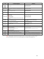
MC361 / MC561 / CX2731MFP
Service & Troubleshooting Guide
© 2012 OkiData Americas, Inc.
Disclaimer
Every effort has been made to ensure that the information in this document is complete, accurate, and up to date. The
manufacturer assumes no responsibility for the results of errors beyond its control. While all reasonable efforts have been made
to make this document accurate and helpful as possible, we make no warranty of any kind, expressed or implied, as to the
accuracy or completeness of the information contained herein. For the most up-to-date service information available, visit our
website, www.okidata.com © Okidata Americas, Inc. 2012
Chapter 1
Maintenance Procedures – Printer / ADF / Scanner
1.1
1.2
1.3
1.4
1.5
1.6
1.7
Chapter 2
Exterior Cleaning
Cleaning the LED lens array
Cleaning the Paper Feed Rollers
Cleaning the Paper Feed Rollers for MP Tray
Cleaning inside the Printer
Cleaning Rollers in the ADF
Cleaning the Document Glass
Service Menus and Adjustments
2.1
2.2
2.3
2.4
2.5
2.6
2.7
2.8
How to Enter the Service Menu
Service Maintenance Menu - Overview
System Maintenance
Panel Maintenance
Copy Maintenance
Scanner Maintenance
Fax Maintenance
Engine Diagnostic Mode (Self-Diagnostic)
2.8.1 Switch Scan Test
2.8.2 Motor & Clutch Test
2.8.3 Test Print
2.8.4 Color Registration Adjustment Test
2.8.5 Density Adjustment Test
2.8.6 Consumable Counter Display
2.8.7 Print counter display
2.8.8 Factory/Shipping Mode Setting
2.8.9 Self-diagnostic function setup
2.8.10 LED Head Serial Number Display
2.8.11 Fuse Checking
2.9
Chapter 3
Switch pressing function when power supply is
turned on
Troubleshooting Print Quality
3.1 Print Quality Problems Overview
3.2 Using New Consumable Units for Testing Purposes
3.3 Things to observe when analyzing Test Pages
3.4 Print-Quality Troubleshooting
Chapter 4
Troubleshooting Paper Feeding
4.1 Troubleshooting Paper Feed
4.1.1 Paper Feed Sensor Details
4.1.2 Jam Removal Procedure
Chapter 5
Troubleshooting Error Codes
2
Chapter 1
1.1
Maintenance Procedures – Printer
Exterior Cleaning
Clean inside and outside of the printer with a clean dry cleaning cloth and small vacuum cleaner
as required.
Note! Be careful not to touch the image drum terminals, the LED lens array and the LED head
connectors.
Turn OFF the power of the MFP.
Turn off the power switch on the printer.
Clean the surface of MFP.
Note! Do not use any liquid other than water and neutral
detergent. The MFP requires no lubrication.
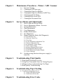
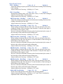
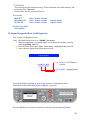
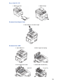
1.2
Cleaning the LED lens array
Lift the scanner.
Press the top cover open button and lift in the direction indicated.
3
Caution!
Failure to proceed with caution may result in burn injury. The fuser unit
gets very hot. Do not touch the surface of the fuser unit.
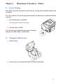
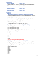
1.3
Wipe the lens surface (at the four positions)
of the LED head with soft tissue paper
gently and lightly.
Cleaning the Paper Feed Rollers
Note! In order not to cause damage to the surface of the roller, please use soft
cloths to clean it.
Pull out the tray.
Wipe the paper feed rollers inside the machine with a soft cloth lightly moistened
with water.
Wipe the paper feed roller on the paper cassette.
Tray 1
4
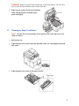
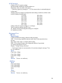
1.4
Cleaning the Paper Feed Rollers for MP Tray
Open the MP tray.
While pressing the tab of the paper feed roller cover to the right, open the cover.
Wipe the paper feed roller with a soft cloth lightly moistened with water.
Close the cover of the paper feed roller.
Close the MP tray.
5
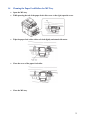
1.5
Cleaning inside the Printer
Note! Don’t touch image drum terminals, LED lens array and LED head connector.
Do not use benzin, thinner and alcohol.
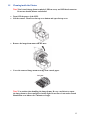
Turn OFF the power of the MFP.
Lift the scanner. Then Press the top cover button and open the top cover.
Remove the image drum unit from the MFP.
Cover the removed image drum cartridge with a black paper.
Note! Use caution when handling the image drums. Be very careful not to expose
the image drum to direct sun light or intense light. Do not leave it out under normal
illumination even indoors for 5 minutes or longer.
6
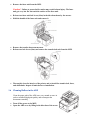
Remove the fuser unit from the MFP.
Caution! Failure to proceed with caution may result in burn injury. The fuser
unit gets very hot. Do not touch the surface of the fuser unit.
Release two fuser unit lock levers (blue) in the direction shown by the arrows.
Hold the handle of the fuser unit and remove it.
Remove the transfer belt from the MFP.
Release two lock levers (blue) and remove the transfer belt unit from the MFP.
Thoroughly clean the interior of the printer and re-install the transfer belt, fuser,
and drum units. Inspect all units before re-installation.
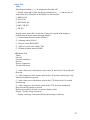
1.6
Cleaning Rollers in the ADF
Clean the paper path of the ADF once every month or more in
order to maintain high print quality and to transport the
documents smoothly.
Turn off the power to the MFP.
Open the ADF cover by lifting in the direction of the arrow.
7
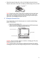
Wipe the document feeding rollers with a soft cloth lightly moistened with water.
Wipe the whole surface of the roller and rubber pad while turning it with your hand.
Note! Clean the entire surface of the rollers by rotating the roller by hand. Some
types of rollers can rotate in one direction only. If the rollers get too dirty, wipe
them with a soft cloth lightly moistened with neutral detergent, and then wipe it
again with a soft cloth lightly moistened with water.
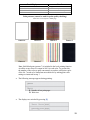
1.7 Cleaning the Document Glass
It is recommended to clean the document glass once a month to maintain image
quality of the printouts.
Open the document glass cover.
Wipe the document holding pad, document glass and ADF document glass
surface with a soft cloth lightly moistened with water.
Caution! Do not use benzine, thinners or alcohol as a cleaning agent. They may
damage the plastic parts of the MFP.
Note! Clean the surface of the document retaining pad, the platen Glass and the
scanning glass with a clean cloth wrung out using clean water or neutral detergent.
8
Chapter 2
Service Menus and Adjustments
The service function is to be used for the purposes of MFP maintenance by the experienced
maintenance/service engineer, and is not open to general users. The respective items of the service
function are contained in the service menu.
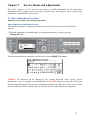
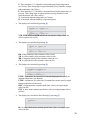
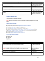
2.1 How to Enter the Service Menu
Enter the service menu by the following operation.
Special Operation of the Hardware Keys
The operation procedure to display the password entry screen of the service menu is described as
follows.
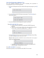
1. When the equipment is in standby mode, access the password entry screen by pressing
[Setting] # 0 1 0 3 *
Enter the password that is required to enter the service menu “000000” (Six zeros).
Caution! The Password can be changed by the “Change Password” menu of the “System
Maintenance” menu. It is highly recommended that you DO NOT change this password. In the event
that the changed password is lost, the main control board would need replacement. This is not a covered
expense under any machine warranty and you will incur the cost of the replacement components.
9
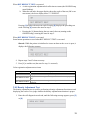
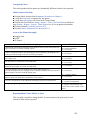
Operation required to exit the Service Mode Screen
In order to complete operations of the service menu, press the Back button until prompted. Highlight
your selection using the arrow keypad and press OK.
Note! If any setting change requires reboot of the MFP and the [BACK] button is pressed, the MFP
will enter the normal operating condition after the MFP reboots.
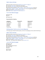
2.2
Service Maintenance Menu – Overview
System Maintenance Screen
System Maintenance Screen
Panel Maintenance Screen
Copy Maintenance Screen
Scanner Maintenance Screen
Fax Maintenance Screen
Print Maintenance Screen
10
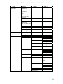
Service Maintenance Menu Structure is shown below.
Menu
System
Maintenance
Panel Maintenance
Copy Maintenance
Scanner Maintenance
Item 1
OKIUSER
*MPS Mode:
MPS. Not shown during
maintenance
Format SD Memory
Card
*Shown only
when an SD card is
connected
Format Flash Memory
Reset Admin Password
All Reset
*MPS mode:
MPS. Not shown during
maintenance
Test Print Menu
Change Password
Check RTC
Save Syslog
Print Syslog
Buzzer Test
Color Copy
Print Check Pattern
Scanner Calibration
Adjust Scan Position
Item 2
Execute
Execute
Execute
New Password
Execute
Execute
Execute
Execute
FBS
ADF (Front-side)
ADF (Back-side)
Adjust Mech.
Adjust CIS
AFE Parameter
Mechanical Test
Item 3
Adjust ADF Scan
Position
Adjust Mech.
Side Reg.
Front Edge
Side Reg.
Front Edge
Back Edge
Front Edge
Back Edge
FB Drive Current
FB Keep Current
ADF Drive Current
ADF Keep Current
Adjust CIS
Check CIS
Set CIS Exposure Time
ADF Test
ADF Test
FBS Test
Simplex/
Duplex
Speed
Execute
Speed
Times
Execute
Sensor Test
ADF Motor Test
Solenoid Test
11
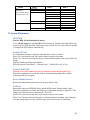
Menu
Fax
Maintenance
*This menu not shown
on models with no fax.
Print Maintenance
Item 1
Service Bit
Country Code
Line Test
T.30 Monitor
Personality
Item 2
Item 3
Tone Send Test
DP Send Test
MF Send Test
Modem Signal Send
Test
Execute
IBM 5577
IBM PPR III XL
EPSON FX
Engine Diag Mode
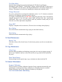
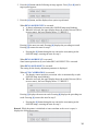
2.3 System Maintenance
OKIUSER
Sets the MFP for the Destination Country.
Note! Should always be set for ODA (North America). Settings other than ODA may
result in erratic MFP operation. When the screen exits the service menu after this setting
is changed, the MFP reboots automatically.
Format SD Card
A confirmation message is displayed when the Enter switch is pressed.
When "No" has been selected, the system returns to the previous menu.
When "Yes" has been selected, the menu is exited and formatting of the inserted SD card
begins.
Displayed under the following conditions:
SD card inserted ("Boot Menu" - "Storage Setup" - "Enable SD Card" is Yes)
Format Flash ROM
Caution! Use of this command is strictly prohibited (contact design before use).
When this command is executed, the menu is exited and formatting of the resident
(onboard) flash device begins.
Reset Admin Password
Returns the administrator password to the factory default value.
All Reset
Returns the content of EEPROM, flash, and the HDD to their factory default values.
When this command is executed, the following confirmation message is displayed: "This
change will reboot the device automatically. Proceed?"
When "No" has been selected, the system returns to the previous menu.
When "Yes" has been selected, the menu is exited immediately and then, after rebooting,
reset processing begins. See the "format scope" sheet for the scope of formatting.
12
Test Print Menu
Switches between displaying and not displaying the "ID Check" and "Engine
Information" in the "Report" - "Print Report" category (default: DISABLE). If this item is
set to "DISABLE," the "ID Check" and "Engine Information" will remain undisplayed at
all times. The printer will reboot after changing the settings and exiting the menu.
Change Password
Set a new password for accessing the maintenance menu. 6 to 12 characters (numerals
and lower-case alphabetic characters) may be entered.
It is highly recommended that you DO NOT change this password. In the event that the
changed password is lost, the main control board and hard disk drive would need
replacement. This is not a covered expense under any machine warranty and you will
incur the cost of the replacement components.
Check RTC
Displays a snapshot of the current time. (The time does not change during display.)
Save Syslog
Saves the network communication log (syslog) to nonvolatile memory.
Print Syslog
Prints the network communication log (syslog).
2.4 Panel Maintenance
Buzzer Test
Select the volume of the forced buzzer. For the buzzer pattern, use the error sound (three
buzzes)
2.5 Copy Maintenance
Color Copy
Switches between enabling and disabling pressing the color start key during copying. If
this is set to "disabled," presses on the color start key in copy mode will be rejected by
the panel.
Print Check Pattern
Starts printing from the panel using a copy evaluation test chart inside the FW.
2.6 Scanner Maintenance
Scanner Calibration
Starts execution of scanner calibration. Instead of being conducted automatically after
operating for a certain period of time, calibration is executed by the user as needed.
During calibration, the fact that calibration is underway is displayed.
Note: Also included under AdminSetting.
13
Adjust Scan Position
FBS – Side Reg.
Value: +8 ~ -8
Default: 0
Adjust the starting read pixel position in the horizontal scanning direction during
book scanning.
Adjust in intervals of one step = 4/600 dpi (=0.17 mm).
FBS – Front Edge
Value: +30 ~ -30
Default: 0
During book scanning, add a value for the basic value (= 5 mm) when reading the
shadow of the front edge of the document.
Adjust in intervals of one step = 4/600 dpi (=0.17 mm).
ADF (Front-side) – Side Reg.
Value: +8 ~ -8
Default: 0
Adjust the starting read pixel position in the horizontal scanning direction when
reading a document from the ADF.
Adjust in intervals of one step = 4/600 dpi (=0.17 mm).
ADF (Front-side) – Front Edge Value: +30 ~ -30
Default: 0
When reading a document from the ADF, add a value for the basic value when
reading the shadow of the front edge of the document. To skip the front edge of
the document, add a negative value.
Increase or decrease the number of motor pulses from detection by the sensor of
the front edge of the media until actual reading starts.
Adjust in intervals of one step = 4/600 dpi (= 0.17 mm).
ADF (Front-side) – Back Edge Value: +30 ~ -30
Default: 0
When reading a document from the ADF, add a value for the basic value when
skipping the back edge of the document. To read the shadow of the back edge of
the document, add a negative value.
Increase or decrease the number of motor pulses from detection by the sensor of
the back edge of the media until actual reading ends.
Adjust in intervals of one step = 4/600 dpi (= 0.17 mm).
ADF (Back-side) – Front Edge Value: +30 ~ -30
Default: 0
When reading a document from the ADF, add a value for the basic value when
reading the shadow of the front edge of the document. To skip the front edge of
the document, add a negative value.
Increase or decrease the number of motor pulses from detection by the sensor of
the front edge of the media until actual reading starts.
Adjust in intervals of one step = 4/600 dpi (= 0.17 mm).
ADF (Back-side) – Back Edge
Value: +30 ~ -30
Default: 0
When reading a document from the ADF, add a value for the basic value when
skipping the back edge of the document. To read the shadow of the back edge of
the document, add a negative value.
Increase or decrease the number of motor pulses from detection by the sensor of
the back edge of the media until actual reading ends.
Adjust in intervals of one step = 4/600 dpi (= 0.17 mm).
Adjust ADF Scan Position
Value: +30 ~ -30
Default: 0
Set the CIS reading position of the ADF for the focusing standard.
Adjust in intervals of one step = 4/600 dpi (= 0.17 mm). This is correlated to
adjustment of the ADF front edge position.
14
Adjust Mech.
FB Drive Current
Value: 1 ~ 140
Connect a panel or PC and set the electric current value of the scanner motor.
FB Keep Current
Value: 1 ~ 140
ADF Drive Current
Value: 1 ~ 140
ADF Keep Current
Value: 1 ~ 140
Adjust CIS
Adjust CIS
Value: simple/R continuous/G continuous/B continuous/All continuous
Sequentially light the designated RGB colors and check them during calibration
configuration duties.
Move the CIS to the standard position.
In the position moved to, sequentially light R, followed by G and B in the same
manner.
Light each color for approximately 3 seconds.
Display "Testing" during execution?
→ On the panel, display "CIS light testing" and "Cancel."
Check CIS
Value: 300dpi/600dpi/1200dpi
-- Results displayed --CCD_SIG9_WID_H 0 x 000000
CCD_SIG2_WID_H 0 x 000000
Check CIS maintenance displays the exposure time at each resolution.
When resolution is set, scanner calibration is conducted at that resolution and the
following results are displayed:
Red-1
Red-2
Green-1
Green-2
Blue-1
Blue-2
Lsync
Note: CIS exposure time varies with resolution.
Set CIS Exposure Time
Value: 0 ~ 4294967295
Change LED exposure time settings, and then read the document using PC Scan.
Reading implemented for the LED exposure time in the settings, without
conducting calibration. A warning is displayed when a value greater than the
Lsync cycle has been set.
Settings are shown below.
Red-1
Red-2
Green-1
Green-2
Blue-1
Blue-2
Lsync
15
AFE Parameter
Change AFE (IC) register settings
Decimal number displayed, decimal number set.
Maximum values vary with each register.
→ Enter the register [n] setting (n: 1 - 9). The current value is read and displayed
on the panel.
Settings values are changed, configuration and reading conducted, and the results
read are displayed on the panel.
R3 (03h)
R38 (26h)
R32 (20h)
R39 (27h)
R33 (21h)
R40 (28h)
R34 (22h)
R41 (29h)
R35 (23h)
R42 (2Ah)
R36 (24h)
R43 (2Bh)
R37 (25h)
R38 (26h)
Change AFE (IC) register settings (3 - 9 settings).
Then, read the document using PC Scan.
W: Display message showing that settings are complete.
R: Display read value.
Mechanical Test
ADF Test
Simplex/Duplex
Conduct mechanical testing (without reading an image).
ADF : Test moving original document (stops when set document has been
moved)
May choose from single- or double-sided feeding.
FBS : CIS moving test (stops after designated number of operations)
Use fastest read speed (30 cpm).
Display "Testing" during execution?
→ On the panel, indicate current number of executions using the message "Test
no. xxx underway."
Speed
Color 300 x 300dpi
Color 300 x 600dpi
Color 600 x 600dpi
Mono
Execute Test no. xxx underway
FBS Test
Speed
Color 300x300dpi
Color 300x600dpi
Color 600x600dpi
Mono
Times
0~65535
Execute Test no. xxx underway
16
Sensor Test
Value:
Should input wording ① ~⑤ be displayed in the right cell?
→ Display in the right cell the wording in parentheses in ① ~⑤ and the state of
each sensor (H/L). Examples of this display are shown below:
① MEDIA H/L
② SCAN H/L
③ REVERSE H/L
④ADF CVR H/L
⑤ FB H/L
Display sensor status (H/L) in real time. Change the content of the display as
needed when the sensor status displayed changes.
① Set-document detection sensor (MEDIA)
② Scanning sensor (SCAN)
③ Reverse sensor (REVERSE)
④ ADF cover-open senor (ADF CVR)
⑤ FB home-position sensor (FB HP)
ADF Motor Test
Value:
Forward
Forward Continuous
Reverse
Reverse Continuous
Test the ADF motor
① After a short press of the button, rotate in the CW direction for 10 seconds and
then stop.
② After a long press of the button, rotate in the CW direction continuously. Stop
when the Stop button is pressed.
③ After a short press of the button, rotate in the CCW direction for 10 seconds
and then stop.
④ After a long press of the button, rotate in the CCW direction continuously.
Stop when the Stop button is pressed.
Deemed successful at all times. No need to display results.
Display "Testing" during execution?
→ Display a message on the panel showing that testing is underway
17
Solenoid Test
Value:
Once
Continuous
After a short press of the button, intake for 2 seconds and then stop.
After a long press of the button, intake for 2 seconds and stop for 3 seconds repeat
Stop when the Stop button is pressed.
Deemed successful at all times. No need to display results.
Display "Testing" during execution?
→ Display a message on the panel showing that testing is underway.
2.7 Fax Maintenance
Note: This menu not shown on models with no fax.
Service Bit
Note: This is displayed only for destinations "JP1" and "JPOEM."
Country Code
This is displayed only for destinations "JP1" and "JPOEM."
Line Test
Tone Send Test
Tone send test conducted.
Value: 2100Hz 1850Hz 1650Hz 1100Hz
DP Send Test
DP send test conducted.
Value: 0 ~ 9, #, * Key
MF Send Test
MF send test conducted.
Value: 0 ~ 9, #, * Key
Modem Signal Send Test
Value:
V.34 (33.6Kbps)
V.34 (28.8Kbps)
V.17 (14.4Kbps)
V.17 (12.0Kbps)
V.17 (9.6Kbps)
V.17 (7.2Kbps)
V.29 (9.6Kbps)
V.29 (7.2Kbps)
V.27 (4.8Kbps)
V.27 (2.4Kbps)
V.21 (0.3Kbps)
Modem-signal send test conducted. 11 types available, including V. 34 (33.6 Kbps).
18
T.30 Monitor
The unit keeps the last transmission log (Tx/Rx commands) on volatile memory, and
print when select "Execute".
If turn off the unit, the records will be lost.
Personality
IBM 5577
IBM PPR III XL
EPSON FX
Values: Enable / Disable
Values: Enable / Disable
Values: Enable / Disable
Default: Enable
Default: Enable
Engine Diag Mode
See Section 2.7
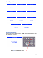
2.8 Engine Diagnostic Mode (Self-Diagnostic)
How to enter self-diagnostic mode
Note! The initial Password is set to "000000" (Six zeros).
1. When the equipment is in standby mode, access the password entry screen by
pressing [Setting] # 0 1 0 3 *
2. Press the Down Arrow until Printer Maintenance is highlighted and press OK
3. Arrow down to Engine Diag Mode and press OK
00.06.08 = PU Firmware
Version
S-Mode = Shipping Mode
Press either [2] key or [8] key to move to the respective self-diagnostic items.
(Menu item scrolls when either [2] key or [8] key is pressed.)
Press the [6] key to execute the selected test. Exit the test by pressing the [4] key.
19
Level 1 Diagnostic Screens
Exiting self-diagnostic mode
When the [4] is pressed from DIAGNOSTIC MODE (Window displaying/Factory state),
the setting window will return.
Press [4] to exit Engine Diag Mode
20
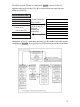
Menu option switching
Only while displayed as shown in a shaded area [XXXXX], the level of the selfdiagnostic mode can be switched. [2] or [8] is used to switch to the option in a nonshaded area [XXXXX].
Normal Operation Mode
LEVEL0- engine status
display
Engine status display
(Heater temperature)
(Ambient temperature and
humidity display)
Voltage display during printing
(TR, CH, DB or SB)
Toner sensor
Waste toner sensor
RFID internal noise motor
Error detail
[2] and [*] held down
in combination (for
three seconds)
SWITCH SCAN
MOTOR & CLUTCH TEST
TEST PRINT
REG ADJUST TEST
[2],[8],[6] and [4]
pressed in
combination
momentarily
DENS ADJ TEST
CONSUMABLE STATUS
PRINTER STATUS
FACTORY MODE SET
SENSOR SETTING
LED HEAD DATA
NVRAM PARAMETER
Holding down [4] or [*] or momentarily pressing [2] or [8] switches between the options
in shaded areas [XXXXX]. [2] or [8] is used to switch between the options in non-shaded
areas [XXXXX]. Holding down [4] restores the display that selects an option.
21
[2] or [8] is used to select the option shown in a shaded area [XXXXX], and pressing [6]
executes the option. [6] or [4] is used to switch to the option in a non-shaded area
[XXXXX], and, after that, [2] or [8] is used to select an option. A selected test is
executed by pressing [6], and ended by pressing [4].
22
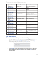
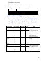
The following is the normal self-diagnostic mode menu:
Option
Self Diagnostic Menu
Item
Adjustment
1 Switch scan test
(See section 2.8.1)
SWITCH SCAN
Performs input sensor and switch
checking.
2 Motor and clutch test
MOTOR&CLTCH TEST
Tests motor and clutch
operation.
3 Test printing
(See section 2.8.3)
TEST PRINT
Prints a test pattern stored in the PU.
4 Color registration
adjustment test
REG ADJUST TEST
Judges the color registration
adjustment mechanism as pass or fail.
DENS ADJ TEST
Judges the density adjustment
mechanism as pass or fail.
CONSUMABLE STATUS
Displays consumable usage.
PRINTER STATUS
Displays consumable life.
FACTORY MODE SET
Switches between the Factory and
Shipping modes
(See section 2.8.2)
(See section 2.8.4)
5 Density adjustment test
(See section 2.8.5)
6 Consumable counter
display
(See section 2.8.6)
7 Consumable life counter
display
(See section 2.8.7)
8 Factory/Shipping mode
setting
(See section 2.8.8)
9 Fuse status display
(See section 2.8.9)
10 Engine parameter setting
Displays the status of the fuses.
SENSOR SETTING
Sets whether to enable or disable
error detection performed by each
sensor.
NVRAM PARAMETER
Must not be used.
(See section 2.8.10)
11 NVRAM parameter setting
(See section 2.8.11)
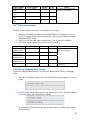
2.8.1 Switch Scan Test
The switch scan test is used for input sensor and switch checking.
1. Enter the self-diagnostic mode (level 1) and, until SWITCH SCAN appears on
the upper display, press [2] or [8] ([2] displays the next test option and [8]
displays the preceding test option). Then press the [6] button.
2. Press [2] or [8] until the option for unit(s) to test, which is shown in table below,
appears on the lower display ([2] displays the next option and [8] displays the
preceding option).
23
3. Press the [6] button. The switch scan test starts, the unit(s)’ name(s) and current
status(es) being displayed.
Operate the unit(s). Display information in the appropriate area(s) of the LCD display
[the information varies depending on the sensor(s)].
4. Press the [#] button to restore the state for step 2.
5. Repeat steps 2 through 4 when necessary.
6. Press [4] to end the test (the state for step 1 is restored).
24
Switch Scan Test
Lower display shows asterisk (*) when function on upper display is unavailable
1
Upper Display
Detail
2
Lower
Display
PAPER ROUTE : PU
TONER SENS
Toner sensor K
CVO UP_LU_FU
Cover-open
switch
REG L/R_OHP_WG
Color
registration
sensor L
HT THERMISTER
HUM_TEMP_DEN 1
BELT_T
Fuser
thermistor
upper
sensor
Humidity
sensor
Belt thermistor
H: Light
shielded
L: Light
reflected
Detail
3
Lower
Display
Detail
Entrance
sensor 1
H: No paper
exists
L: Paper exists
Write sensor
Toner Y
Sensor
H: Light
shielded
L: Light
reflected
Toner M
Sensor
Face-up coveropen sensor
H - Close
L – Open
AD value:
***H
Color
registration
sensor R
AD value:
***H
Fuser thermistor
AD value:
lower
***H
sensor
AD value:
***H
Temperature
sensor
4
Lower
Display
H: No paper
exists
L: Paper
exists
H: Light
shielded
L: Light
reflected
TAG ID
DISTONER
FULL_BOX
Waste toner
sensor
T1 PE_PNE_CVO_CA
T1 HOP_LIFT
Tray-1 paperend
sensor
Hopping sensor
T2 PE_PNE_CVO_CA
Tray-2 paperend
sensor
T2 HOP_LF_FED
2nd-Hopping
Sns
DUP RA_FNT
Exit sensor
Toner C
Sensor
Lower
Display
H: No paper
exists
L: Paper
exists
H: Light
shielded
L: Light
reflected
H: Close
L. Open
AD value:
***H
AD value:
***H
Density
sensor (K)
AD value:
***H
Heater frame
thermistor
AD value:
***H
Density sensor
(YMC)
AD value:
***H
I/D Up Down
Sns
H: Up
L: Down
UID:
***H
AD value:
***H
ID UP/DOWN
TAG COLOR
Detail
UID:
***H
H: Light not
reflected
L: Light
reflected
TAG ID
UID:
***H
TAG ID
UID:
***H
H: No paper
exists
L: Paper
exists
TAG ID
Cassette sensor
H: No paper
exists
L: Paper
exists
H: No paper
exists
L: Paper
exists
H: No paper
exists
L: Paper
exists
Duplex rear
sensor
H: Light
shielded
L: Light
reflected
Tray 2
entrance sensor
H: No paper
exists
L: Paper exists
Duplex front
sensor
H: No paper
exists
L: Paper exists
25
H. Cassette
exists
L. Cassette
does not
exist
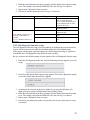
2.8.2 Motor & Clutch Test
The motor and clutch test is used for motor and clutch testing.
1. Enter the self-diagnostic mode (level 1) and, until MOTOR & CLUTCH TEST
appears on the upper display, press [2] or [8] ([2] displays the next test option and
[8] displays the preceding test option). Then press the [6] button.
2. Press [2] or [8] until the option for a unit to test, which is shown in the below
table, appears on the lower display ([2] displays the next option and [8] displays
the preceding option).
3. Press the [6] button. The motor and clutch test starts, the unit’s the name starting
to blink, and the unit being driven for10 seconds.
Note: The state for step 2 is restored after the 10-second driving of the unit. The
unit is driven again by pressing an appropriate button.
The clutch solenoid repeatedly turns on and off in normal printing driving (a
motor is driven together with the solenoid when it cannot be driven solely
because of its mechanical structure). * ID UP/DOWN continues driving until
the [#] button is pressed.
The clutch solenoid is kept driven by holding down the [6] button (for two
seconds) to determine a motor.
4. Press the [#] button to stop driving the unit (the display continues indicating the
unit).
5. Repeat steps 2 through 4 when necessary.
6. Press [4] to end the test (the state for step 1 is restored).
26
Motor & Clutch Restrictions
Unit name displayed
ID MOTOR
BELT MOTOR
FUSER_MOTOR
REGIST MOTOR
T1 HOPPING MOTOR
FRONT MOTOR
REGIST SHUTTER
DUPLEX MOTOR
DUPLEX CLUTCH
T2 HOPPING MOTOR
T2 FEED CLUTCH
ID UP/DOWN
LV FAN TEST
ID FAN TEST
FRONT FAN TEST
Driving restriction
All of the (black, yellow,
magenta and cyan) image drums
must be removed.
All of the (black, yellow,
magenta and cyan) image drums
must be removed.
–
–
–
–
–
–
–
–
–
The top and front cover must be
closed.
–
–
–
Remarks
–
–
–
–
–
–
–
–
–
Option
Option
–
–
–
–
Note: Display while ID UP/DOWN is in progress
***: Identifies the number of executions
Display after holding down REGIST SHUTTER [6] button
***: Identifies the number of executions
2.8.3 Test Print
The test printing is used for printing test patterns stored in the PU. The controller stores
the other patterns.
The test printing cannot be used to check print quality.
1. Enter the self-diagnostic mode and, until TEST PRINT appears on the upper
display, press [2] or [8] ([2] displays the next test option and [8] displays the
preceding option). Then press the [6] button.
2. A setting option applied only to test printing appears on the lower display. Press
[2] or [8] until a target option appears ([2] displays the next option and [8]
displays the preceding option). Then press the [6] button. [Go to step 5 when the
options do not need to be set (left set to their defaults)].
27
3. The setting option and its setting appear on the upper and lower displays,
respectively. Pressing [2] displays the next setting and pressing [8] displays the
preceding setting (the setting last displayed is applied. Press [4] to accept the
setting and return to step 2. Repeat step 3 when necessary.
Display
Setup Value
PRINT EXECUTE
-
TEST PATTERN
0
TEST CASSETTE
PAGE
COLOR
TRAY1
TRAY2
MPT Tray
0000
ON
OFF
2 PAGES STACK
DUPLEX
OFF
1 PAGES STACK
Function
Starts’ printing with the press of [6] button, and ends
printing with the press of the [#] button.
0: Prints a blank page.
1 to 7: - See the next section (pattern printing)
8 to 15: Each prints a blank page.
Selects a paper source.
TRAY2 is not displayed when the tray 2 is not
installed.
Sets the number of test copies to print.
Selects color or monochrome printing.
* ON and OFF are provided for each color when the
setting ON is specified.
Performs duplex printing using a two pages layout.
Selects turning off duplex printing.
Performs duplex printing using a one page stack layout.
Default is in shaded areas (XXX). Set settings are enabled only in this test mode (not
written into the EEPROM)
Note:
PAGE: Moves its input digit with [2] or [8]. The setting for this option is incremented by
pressing the [*] button, and decremented by pressing the [#] button. Note that, when left
set, the setting 0000 endlessly prints pages.
COLOR: When set to ON, with the press of the [6] button, displays the information
shown below.
Setting option for printing colors: Moves its input position with [2] or [8]. The setting for
each color is switched between ON and OFF by the press of the [*] or [#] button. The
panel display is restored to the previous one by pressing [4].
4. With PRINT EXECUTE displayed on the lower display by the operation in step
2, pressing the [6] button executes test printing by using the setting(s) made in
steps 2 and 3.
The test printing is cancelled by pressing the [#] button.
When detected in starting or performing the test printing, an alarm shown in the
detail section of the following list is displayed on the operator panel, stopping the
printing.
28
Panel Display
Detail
PAPER END SELECTED TRAY
SELECTED TRAY IS NOT INSTALLED
REMOVE PAPER OUT OF DUPLEX
INSTALL CASSETTE TRAY OPEN
No paper exists.
The selected tray is not installed.
An internal error of the duplex unit.
A cassette is slid out.
Print patterns (cannot be used for print quality checking)
0 and 8 to 15: Each prints a blank page.
Pattern 0
Pattern 1
Pattern 2
Pattern 3
Pattern 4
Pattern 5
Pattern 6
Pattern 7
Note: Solid black print (pattern 7) is included in the local printing function.
An offset occurs when it is output at 100% in each color. To prevent this,
the number of the colors to print concurrently to produce solid print copies
of the No. 7 needs to be limited not more than two by making print color
settings as instructed in step 3
The following message appears during printing:
P: Number of test print pages
W: Wait time
The displays are switched by pressing [2].
29
U: Three asterisks (***) identifies a measured upper heater temperature
(in Celsius). Three sharp signs in square brackets ([###]) identifies a target
print temperature (in Celsius).
L: Three asterisks (***) identifies a measured lower heater temperature (in
Celsius). Three sharp signs in square brackets ([###]) identifies a read
lower thermistor AD value (in hex).
T: A measured ambient temperature (in Celsius).
H: A measured ambient humidity (in percent figures).
The displays are switched by pressing [2].
YTR, MTR, CTR and KTR indicate the set transfer voltage values for
colors, respectively (in kV).
The displays are switched by pressing [2].
KR: A black transfer roller resistance value (in uA).
YR: A yellow transfer roller resistance value (in uA).
MR: A magenta transfer roller resistance value (in uA).
CR: A cyan transfer roller resistance value (in uA).
The displays are switched by pressing [2].
ETMP: A parameter for correction of constant hopping motor speed (an
ambient temperature) (in decimal).
UTMP: A parameter for correction of constant fuser motor speed (a target
fusing temperature) (in decimal).
REG: A hopping motor constant-speed timer value (a set input/output
value) (in hex).
EXT: A fuser motor constant-speed timer value (a set input/output value)
(in hex).
The displays are switched to the following by pressing [2].
ID: An image drum motor constant-speed timer value (a set input/output
value) (in hex).
30
The displays are switched pressing [2].
BELT: A belt motor constant-speed timer value (a set input/output value)
(in hex).
FRM: Three asterisks in square brackets ([***]) identifies a read frame
thermistor AD value (in hex).
Three cross signs in brackets ((xxx)) identifies a frame temperature (in
Celsius).
The displays are switched pressing [2].
DB: A developing voltage setting table identification number (in hex).
The displays are switched pressing [2].
TR1: A transfer voltage parameter VTR1 table identification number (in
hex).
TR2: A transfer voltage parameter VTR2 table identification number (in
hex).
The displays are switched pressing [2].
TROFF: A transfer off voltage setting table identification number (in hex).
BELT: Three cross signs and a minus sign (xxx-) identifies a read belt
thermistor AD value (in hex).
Three asterisks and a minus sign (***-) identifies a belt temperature (in
hex).
5. Repeat steps 2 through 4 when necessary.
6. Press the [#] button to end the test (the state for step 1 is restored).
31
2.8.4 Color Registration Adjustment Test
The color registration adjustment test is used for adjusting color registration or
investigating the causes of color misregistration.
1. Enter the self-diagnostic mode and, until the following message appears, press [2]
or [8].
2. Press the [6] button and the following message appears. Press [2] or [8] until a
target option appears.
3. Press the OK button, and the displayed test option is performed.
When REG ADJ EXECUTE is executed:
a. A color registration adjustment test starts (the ONLINE lamp starts
blinking).
b. When the test ends, the upper display shows the result of the test (OK or
an error name), and the lower display shows ****RESULT.
Pressing [2] displays the next test result. Pressing the [8] displays the preceding
test result. Pressing [4] restores the state for step 2.
Remark: While the printer is initialized or issues an alarm or the cover is open, it
displays the following message:
c. Pressing the [#] button during the test cancels the test (turning on the
ONLINE lamp), restoring the state for step 2.
When REG ADJ RESULT is executed:
Same button operations as used when REG ADJ EXECUTE is executed.
32
When BLT REFLECT TEST is executed:
a. A color registration adjustment belt reflection test starts (the ONLINE lamp
starts blinking).
b. When the test ends, the upper display shows the result of the test (OK or an
error name), the lower display shows ****RESULT.
Pressing [2] displays the next test result. Pressing [8] displays the preceding test
result. Pressing [4] restores the state for step 2.
c. Pressing the [#] button during the test cancels the test (turning on the
ONLINE lamp), restoring the state for step 2.
When BLT REFLECT RSLT is executed:
Same button operations as used when BLT REFLECT TEST is executed.
Remark: While the printer is initialized or issues an alarm or the cover is open, it
displays the following message.
4. Repeat steps 2 and 3 when necessary.
5. Press [4] to end the test (the state for step 1 is restored).
Color registration adjustment test items
Display Detail
REG ADJ EXECUTE
REG ADJ RESULT
BLT REFLECT TEST
BLT REFLECT RSLT
Display Detail
Executes color registration adjustment.
Displays the result of color registration adjustment.
Judges whether color registration adjustment belt reflection is proper or
not
Displays the result of color registration adjustment belt reflection
judgment.
2.8.5 Density Adjustment Test
The density adjustment test is used for performing a density adjustment function test and
displaying the result of it to judge whether the density adjustment mechanism is proper.
1. Enter the self-diagnostic-mode and, until the following message appears, press [2]
or [8].
33
2. Press the [6] button and the following message appears. Press [2] or [8] until a
target option appears.
3. Press the [6] button, and the displayed test option is performed:
When DENS ADJ EXECUTE is executed:
a. A density adjustment test starts (the ONLINE lamp starts blinking).
b. When the test ends, the upper display shows the result of the test (OK or
an error name), the lower display shows ****RESULT.
Pressing [2] the next test result. Pressing [8] displays the preceding test result.
Pressing [4] restores the state for step 2.
c. Pressing the [#] button during the test cancels the test (turning on the
ONLINE lamp), restoring the state for step 2.
When DENS ADJ RESULT is executed:
Same button operation as (b) used when REG ADJ EXECUTE is executed.
When DENS ADJ PAR-SET is executed:
The setting for the density adjustment parameter is displayed.
When AUTO CALIBRATION is executed:
a. The density sensor sensitivity correction value is automatically set (the
ONLINE lamp starts blinking).
b. When the test ends, the upper display shows the result of the test (OK or
an error name), the lower display shows ****RESULT.
Pressing [2] displays the next test result. Pressing [8] displays the preceding test
result. Pressing [4] restores the state for step 2.
c. Pressing the [#] button during the test cancels the test (turning on the
ONLINE lamp), restoring the state for step 2.
Remark: While the printer is initialized or issues an alarm or the cover is open, it
displays the following message:
34
4. Repeat step 3 when necessary.
5. Press [4] to end the test (the state for step 1 is restored).
Density adjustment test items
Display
Detail
DENS ADJ EXECUTE
DENS ADJ PAR-SET
DENS ADJ RESULT
AUTO CALIBRATION
AUTO CALIB BLACK
Executes density adjustment.
Sets a control value for auto density adjustment.
Displays the result of density adjustment.
Automatically sets a density sensor sensitivity correction value.
Automatically sets a black density sensor sensitivity correction value.
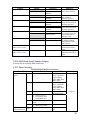
2.8.6 Consumable Counter Display
The consumable counter display is used for viewing the usage of consumables.
1. Enter the normal self-diagnostic mode and, until CONSUMABLE STATUS
appears, press [2] or [8] ([2] displays the next test option and [8] displays the
preceding test option). Then press the [6] button.
2. Press [2] or [8], and the usage of each consumable appears (the [*] or [#] button is
disabled).
3. Press [4] to end the option (the state for step 1 is restored).
Lower Display
Format
Unit
Detail
K-ID UNIT
Y-ID UNIT
M-ID UNIT
C-ID UNIT
Upper Display
********IMAGES
********IMAGES
********IMAGES
********IMAGES
Decimal
Decimal
Decimal
Decimal
Images
Images
Images
Images
FUSER UNIT
********PRINTS
Decimal
Prints
TR BELT UNIT
********IMAGES
Decimal
Images
K-TONER
(FULL)
Y-TONER
(FULL)
M-TONER
(FULL)
C-TONER
(FULL)
K-STC MODE
CNT
Y-STC MODE
CNT
M-STC MODE
CNT
C-STC MODE
CNT
********%
Decimal
%
Each display the number of turns
performed to date after the
installation of a new image drum
unit, converted on an A4 and
three-pages-per job basis.
Displays the number of pages
printed to date after the
installation of a new fuser unit.
Displays the number of pages
printed to date after the
installation of a new belt unit.
Each displays the usage of toner
of a color.
********%
Decimal
%
********%
Decimal
%
********%
Decimal
%
********TIMES
Decimal
Times
********TIMES
Decimal
Times
********TIMES
Decimal
Times
********TIMES
Decimal
Times
Each displays the print dot count
of toner of a color (life counter
value after the printer goes into
operation).
35
Upper Display
K OVER RIDE
CNT
Y OVER RIDE
CNT
M OVER RIDE
CNT
C OVER RIDE
CNT
Format
Unit
********TIMES
Lower Display
Decimal
Times
********TIMES
Decimal
Times
********TIMES
Decimal
Times
********TIMES
Decimal
Times
Detail
Each displays the extension life
count of a toner cartridge.
2.8.7 Print counter display
The print counter display is used for viewing print counter values.
1. Enter the self-diagnostic mode and, until PRINTER STATUS appears, press [2]
or [8] ([2] displays the next test option and [8] displays the preceding test option).
Then press the [6] button.
2. Press [2] or [8], and each count is printed (the [*] or [#] button is disabled).
3. Press [4] to end the option (the state for step 1 is restored).
Upper Display
K–
IMPRESSIONS
Y–
IMPRESSIONS
M–
IMPRESSIONS
C–
IMPRESSIONS
TOTAL SHEET
CNT
Format
Unit
********IMAGES
Lower Display
Decimal
Images
********IMAGES
Decimal
Images
********IMAGES
Decimal
Images
********IMAGES
Decimal
Images
********COUNTS
Decimal
Prints
Detail
Number of printed sheets for
each color is displayed.
Total number of printed sheets
is displayed.
2.8.8 Factory/Shipping Mode Setting
The Factory/Shipping mode setting is used for switching from the Factory to Shipping
mode.
1. Enter the self-diagnostic mode and, until the following message appears, press [2]
or [8].
2. Press [2] or [8] and the following message appears. Press [2] or [8] until an option
to set (refer to the table shown below) appears.
3. By pressing the [6] button with the option on the display, a setting for the option
can be selected.
36
4. Hold down the [6] button (for three seconds) with the display showing the setting
to set. The setting is stored in the EEPROM. The state for step 2 is restored.
5. Repeat steps 2 through 4 when necessary.
6. Press [4] to end the option (the state for step 1 is restored).
Display
FACTORY MODE
Settings
FACTORY MODE
SHIPPING MODE
FUSE INTACT
BELT UNIT ******
Note! Indicates whether fuse is
INTACT or BLOWN. Six
asterisks
(******) identifies INTACT or
BLOWN.
FUSE UNIT ******
ID UNIT ******
Function
Sets up the Factory work mode.
This is a production mode.
Note! The unit should always be
set for Shipping mode or erratic
operation may result.
Sets up the Shipping mode for
normal operation.
Checks the FUSE status of the
transfer belt unit.
Checks the FUSE status of the
fuser.
Checks the FUSE status of the ID
unit.
2.8.9 Self-diagnostic function setup
The self-diagnostic function setup is used for enabling or disabling the error detection by
sensors. The detection can be enabled or disabled temporarily for troubleshooting.
Allowing for setting engine operation options for which expert knowledge is required to
be handled, these self-diagnostic setup should be used carefully.
Be sure to restore the default settings of used options of the self-diagnostic function setup.
1. Enter the self-diagnostic mode and, until the following message appears, press [2]
or [8].
2. Press [2] or [8] and the following message appears. Press [2] or [8] until an option
to set (refer to the table shown below) appears.
3. A setting can be selected on the lower display by pressing the [6] button. [2]
displays the next setting and [8] displays the preceding setting.
4. Hold down the [6] button (for three seconds) with the display showing the setting
to set. The setting is stored in the EEPROM. The state for step 2 is restored.
5. Repeat steps 2 through 4 when necessary.
6. Press [4] to end setting the option (except where not in step 4) (the state for step 1
is restored).
37
Display
Setting
Behavior
TONER SENSOR
ENABLE
DISABLE
Performs detection.
Does not perform
detection.
Performs checking.
Does not perform
checking.
Performs checking.
Does not perform
checking.
Performs detection.
Does not perform
detection.
Has the printer to pause.
Does not have the
printer to pause.
BELT UNIT CHECK
ENABLE
DISABLE
ID UNIT CHECK
ENABLE
DISABLE
UP/DOWN SENSOR
ENABLE
DISABLE
REG ADJUST ERROR
ENABLE
DISABLE
DRUM OVER LIFE
STOP
CONTINUANCE
Does not extend life.
Extends life.
WR POINT REV
TBL=**H±*.***mm
00H~FFH
A correction value.
BOTTOM WRT POINT
TBL=**H±*.***mm
00H~FFH
A tear-off value.
Function
Enables or disables the
toner sensor operation.
Enables or disables the
belt installation
checking operation.
Enables or disables the
image drum installation
checking operation.
Enables or disables the
image drum installation
checking operation.
Enables or disables the
error display based on a
color misregistration
detection value.
Sets whether to enable
or disable extending
image drum life at the
end of the life.
Adds a correction value
for the default writing
point.
Sets a tear-off length
from the bottom edge of
paper.
Default is in shaded area
2.8.10 LED Head Serial Number Display
Not used for servicing the MFP at this time.
2.8.11 Fuse Checking
Fuse Name
CU/PU board
(CLP)
F2
Service Call 128 Error 08
F4
Service Call 122
F6
Cover open
F3
F5
F501
High-voltage
board (ORZ board)
MC561/MC361/MC351 Fuse Errors
Error Description
Insert Point
F501
Service Call 121
The operator panel
backlight blackout
No display on the operator
panel
Service Call 131 to 134
Blank page printing
Service Call 121
Front fan, hopping
motor, registration
clutch, hopping
clutch, MPT clutch,
duplex clutch
Rear fan, hopping
motor, registration
clutch, hopping
clutch, MPT clutch,
duplex clutch
High-voltage board,
ID fan, belt motor
PU 5V
Resistance
1 Ω or less
CU/PU 3.3V
LED head 5V
High voltage board
24V
38
Fuse Name
SU board (MHC)
F1
F2
F3
F501
F502
F503
Error Description
No display on the
operator panel
No display on the
operator panel
Lamp Error
Carriage Error
Lamp Error
No display on the
operator panel
Insert Point
Resistance
SU, FAX, OPE
SU, OPE
CIS
FB/ADF Motor
Clutch, Solenoid,
CIS
SU, FAX, OPE
1 Ω or less
2.9 Switch pressing function when power supply is turned on
When power supply of printer is turned on, the functions of usable switches are as follows. And,
the switches below are effective when pressed before LED is lighted in the special start
confirming pattern.
1. [1] key and [ ] key
Despite of warning/error, always start by online mode (factory support
function).
2. [ ] key and [STOP] key
Initialize NIC settings to Factory defaults.
When executing this initialize, all network settings will be returned to factory
defaults.
3 Troubleshooting Print Quality
3.1 Print Quality Problems Overview
Print-quality defects can be attributed to printer components, consumables, media,
internal software, external software applications, and environmental conditions. To
successfully troubleshoot print-quality problems, eliminate as many variables as possible.
The first step is to generate prints using printable pages embedded in the printer on paper
from the Supported Media List. Use paper from a fresh, unopened ream that is acclimated
to room temperature and humidity. If the print-quality defect is still present when printing
on approved media, then investigate software applications and environmental conditions.
The printers use separate Imaging Units to develop a latent image for each color where
the colors are combined on the Transfer Unit to form the final image. In most cases,
print-quality defects are the result of one particular component in the print engine, See
the Repeating Defects chart. When a single component of the Imaging Unit is causing a
print quality defect, replace the Imaging Unit.
When analyzing a print-quality defect, first determine if the defect occurs in all colors or
only one color and if it is repeating or random. Continuous defects in the process
direction, such as voids and lines, are the most difficult to diagnose. Inspect the visible
surfaces of all rollers for obvious defects. If no defects are observed, replace the Imaging
Unit, Transfer Unit, and Fuser one at a time until the defect is eliminated.
Defects Associated with Specific Printer Components
Some print-quality problems can be associated with specific assemblies, the most
common problems and the associated assemblies are listed below. Also, refer to the
39
printer’s Troubleshooting Print-Quality Problems pages or a specific print-quality
troubleshooting procedure for more information.
Imaging Unit
Streaks in Process Direction (in the direction of feed, parallel with paper travel)
Banding in Scan Direction (across the page, perpendicular to paper travel)
Uneven Density
Voids
Repeating Defects
Mis-registration
Transfer Unit
Toner on the back side of the printed page (simplex mode)
Light Prints
Repeating Defects
Mis-registration - only when there is obvious damage to the belt.
Fuser
Hot or Cold Offsetting
Repeating Defects
Dark Streaks in Process Direction
LED Head
Streaks in the Process Direction
Uneven Density in the Scan Direction
Test Prints
A variety of test prints are available to aid in determining the quality of output from the
printer and to assist in troubleshooting. See sections 2.8.3 and 2.8.5 for details.
3.2 Using New Consumable Units for Testing Purposes
The printer unit will allow you to utilize new consumable units for print quality diagnosis
and troubleshooting purposes.
Note! When using new units (Drum, Transfer Belt, Fuser) to assist in troubleshooting,
you should temporarily set the printer to “Factory Mode” (See Section 2.8.8). Setting
to factory mode will allow you to use brand new units for testing purposes without
cutting the fuse.
Caution! Be sure to reset the printer to “Shipping Mode” when testing is complete.
Leaving the printer in Factory Mode may cause erratic operation of the MFP.
3.3 Things to observe when analyzing Test Pages
Streaks in Process Direction (in the direction of feed, parallel with paper travel)
Banding in Scan Direction (across the page, perpendicular to paper travel)
Uneven Density
Voids
Repeating Defects
Mis-registration
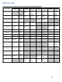
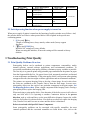
Note: Consult the “Repeating Defect Spacing Chart” below.
40
Repeating Defects Spacing
Component
Imaging Drum
Developer Roller
Charge Roller
Supply Roller
Fuser Belt
Heat Roller
Transfer Roller
Defect Spacing
94.3 mm
30.2 mm
29.9 mm
43.1 mm
94.2 mm
85.4 mm
37.7 mm
Defect Location
Imaging Unit
Imaging Unit
Imaging Unit
Imaging Unit
Fuser
Fuser
Transfer Unit
3.4 Print-Quality Troubleshooting
Light Prints in All Colors
The overall image density is too light in all colors. If the image is light in only one color,
see "Light Print in Only One Color".
Initial Actions to Perform
■ Perform Initial Actions from Maintenance Procedures in Chapter 1.
■ Verify the media used is supported by this printer.
■ Verify the media settings are correct at the Control Panel.
■ Print the ID Check Pattern (Setting - Reports – Print – ID Check Pattern) and
Demo page (Reports – Information – Demo Page) to see if it is an application problem.
■ Perform isolation Test Prints (Section 2.8.3).
■ Run the Density Adjustment Test in Section 2.8.5.
Areas of the Printer that Apply
■ Imaging Unit
■ LED Head
■ Transfer Unit
■ HVPS
■ PU Board
Troubleshooting Steps
Resolution
1. Verify all packaging material has been removed form the toner cartridges
Yes – Go to Step 2
No - Remove packing material
2. Remove the Imaging Units and the Transfer Unit and check for toner contamination on the
high voltage contacts. Are the contacts contaminated?
Yes – Clean the contacts
No - Go to Step 3
3. Are the LED Heads dirty? Clean the heads with a clean, lint-free cloth. Did this correct the
problem?
Yes – Complete
No - Go to Step 4
4. Are the wiring harnesses on the LED Heads undamaged, properly routed and seated?
Yes – Repair / Replace Harnesses
No - Go to Step 5
5. Inspect the high-voltage wiring harness. Reseat the wiring Harness. Did this correct the
problem?
Yes – Complete
No - Replace in the following order:
Transfer Unit / Imaging Unit / HVPS /
CUPU Board
41
Light Prints in Only One Color
Only one color; yellow, magenta, cyan, or black, is too light on the printed image.
Initial Actions to Perform
■ Perform Initial Actions from Maintenance Procedures in Chapter 1.
■ Print the ID Check Pattern (Setting - Reports – Print – ID Check Pattern) and
Demo page (Setting - Reports – System – Demo Page)
■ Perform isolation Test Prints (Section 2.8.3).
■ Check that the Toner Cartridge pull strip is completely removed from the affected color.
■ Run the Density Adjustment Test in Section 2.8.5.
Areas of the Printer that Apply
■ Imaging Unit
■ LED Head
■ Transfer Unit
■ HVPS
■ PU Board
Troubleshooting Steps
Resolution
1. Verify all packaging material has been removed form the toner cartridges
Yes – Go to Step 2
No - Remove packing material
2. Print the 100% Solid Fill test print. Can the problem be isolated to one primary color?
Yes – Go to Step 3
3. Remove the Toner Cartridge and check for toner starvation in the Imaging Unit. Is there
evidence of toner starvation
Yes – Replace the Toner Cartridge
No - Go to Step 4
4. Remove the Imaging Units and the Transfer Unit and check for toner contamination on the
high voltage contacts. Are the contacts contaminated?
Yes – Clean the contacts
No - Go to Step 5
5. Are the LED Heads dirty? Clean the heads with a clean, lint-free cloth. Did this correct the
problem?
Yes – Complete
No - Go to Step 6
6. Swap the LED Head of the problem color with any other LED Head.
Print a Solid Fill Test Pattern. Has the problem moved with the LED Head?
Yes – Replace the LED Head
No - Go to Step 7
7. Are the wiring harnesses on the LED Heads undamaged, properly routed and seated?
Yes – Reseat the wiring Harnesses
No - Replace in the following order:
Transfer Unit / LVPS / CUPU Board
Blank Prints
Initial Actions to Perform
■ Perform Initial Actions from Maintenance Procedures in Chapter 1.
■ Perform isolation Test Prints (Section 2.8.3) to isolate the problem between the CU
Board and the PU Board.
Areas of the Printer that Apply
■ Imaging Unit
■ LED Head
■ PU Board
42
Troubleshooting Steps
1. Print a 100% Solid Fill Test Print. Is the entire test print blank?
2. Remove the Toner Cartridge and check for toner starvation inside the Imaging Unit. Is
there evidence of toner starvation?
3. Are the LED Heads dirty? Clean the heads with a clean, lint-free cloth.
Did this correct the problem?
4. Are the wiring harnesses on the LED Heads undamaged, properly routed and seated?
5. Inspect the high-voltage wiring harness. Reseat the wiring Harness. Did this correct the
problem?
Resolution
Yes – Go to Step 2
No - Have the customer check there
application and printer settings.
Yes – Replace the Toner Cartridge.
No - Go to Step 3
Yes – Complete
No - Go to Step 4
Yes – Go to Step 5
No - Repair / Replace Harnesses
Yes – Complete
No - Replace in the following order:
Transfer Unit / LVPS / HVPS /
CUPU Board
Mottled or Splotchy Prints
The print image has a mottled appearance.
Note! This defect is known to occur at low humidity, and when printing on heavy weight
media.
Initial Actions to Perform
■ Perform Initial Actions from Maintenance Procedures in Chapter 1.
■ Verify the media used is supported by this printer.
■ Verify the media settings are correct at the Control Panel.
■ Print the ID Check Pattern (Setting - Reports – Print – ID Check Pattern) and Demo
page (Setting - Reports – System – Demo Page) to see if it is an application problem.
■ Perform isolation Test Prints (Section 2.8.3).
■ Run the Density Adjustment Test in Section 2.8.5.
Areas of the Printer that Apply
■ Imaging Unit
■ LED Head
■ HVPS
■ PU Board
Troubleshooting Steps
1. Ensure the media is approved and the Control Panel and driver settings match the loaded
media. Try different media to verify consistent, reproducible problem.
2. Print the configuration page to verify the operating environment.
NOTE: Low humidity, less than 20% relative humidity can cause mottling on prints.
3. Check for toner contamination on the high voltage contacts. Remove the Imaging Units
and Transfer Unit. Is there contamination?
4. Check / Replace the Transfer Unit. Is the problem resolved?
Resolution
Yes – Go to Step 2
No - Have the customer load
approved media or correct the
settings.
Yes – Go to Step 3
No - Advise customer regarding the
printer’s environmental
specifications.
Yes – Clean the contacts
No - Go to Step 4
Yes – Complete
No - Replace in the following order:
LVPS / HVPS / CUPU Board
43
Unexpected Colors
The colors produced by the printer are dramatically different from the color expected.
Initial Actions to Perform
■ Perform Initial Actions from Maintenance Procedures in Chapter 1.
■ Verify the media used is supported by this printer.
■ Verify the media settings are correct at the Control Panel.
■ Print the ID Check Pattern (Setting - Reports – Print – ID Check Pattern) and Demo
page (Setting - Reports – System – Demo Page) to see if it is an application problem.
■ Perform isolation Test Prints (Section 2.8.3).
■ Run the Density Adjustment Test in Section 2.8.5.
Areas of the Printer that Apply
■ Imaging Unit
■ HVPS
■ PU Board
Troubleshooting Steps
Resolution
2. Print a configuration page to check the Imaging Unit life remaining. If the Imaging Unit is
reaching its maximum image count, this can reduce print-quality.
Yes – Complete, the problem is with
the Customer application.
No - Go to Step 2.
Yes – replace the Imaging Unit.
No - Go to Step 3.
3. Print the 100% Solid Fill Test pattern and check for any missing colors. Is the problem
with a single color?
Yes –Go to Step 4.
No - Go to Step 6
4. Is there debris or contamination on the LED Head?
Yes – Clean with a dry, lint free cloth.
No - Go to Step 5
Yes – Replace the defective LED Head
No – Go to Step 6
1. Print the ID Check Pattern / Demo Page and evaluate the colors. Are the colors on the test
pages representative of what the customer expects?
5. Swap the LED Head of the problem color with any other LED Head. Print a Solid Fill Test
Pattern. Has the problem moved with the LED Head?
6. Swap the Imaging Unit of the problem color with any other Imaging Unit.
NOTE: Remove the keys before swapping. Print a Solid Fill Test Pattern to check for defects.
Has the problem color moved with the Imaging Unit?
Yes – Replace the Imaging Unit
No - Go to Step 7.
7. Check for toner contamination on the high voltage contacts. Remove the Imaging Units
and the Transfer Unit and Is there contamination on the contacts?
Yes – Clean the contacts.
No - Go to Step 8.
8. Are the wiring harnesses on the LED heads undamaged, properly routed and seated?
Yes – Go to Step 9.
No - reseat the wiring harness.
Yes – reseat the wiring harness.
No - Replace in the following order:
Transfer Unit / LVPS / HVPS / CUPU
Board
9. Inspect the high-voltage wiring harness.
Repeating Bands, Lines, Marks, or Spots
This is usually caused by a damaged roller. In some instances, the spots may be dark
instead of white and are repeated.
44
Initial Actions to Perform
■ Perform Initial Actions from Maintenance Procedures in Chapter 1.
■ Verify the media used is supported by this printer.
■ Verify the media settings are correct at the Control Panel.
■ Print the ID Check Pattern (Setting - Reports – Print – ID Check Pattern) and Demo
page (Setting - Reports – System – Demo Page) to see if it is an application problem.
■ Perform isolation Test Prints form Section 2.8.3.
■ Run the Density Adjustment Test in Section 2.8.5.
Areas of the Printer that Apply
■ Imaging Unit
■ Fuser
■ Transfer Unit
Repeating Defects Spacing
Component
Imaging Drum
Developer Roller
Charge Roller
Supply Roller
Fuser Belt
Heat Roller
Transfer Roller
Defect Spacing
94.3 mm
30.2 mm
29.9 mm
43.1 mm
94.2 mm
85.4 mm
37.7 mm
Defect Location
Imaging Unit
Imaging Unit
Imaging Unit
Imaging Unit
Fuser
Fuser
Transfer Unit
Mis-Registration, Color Layers Not Correctly Registered
The image appears blurred and the primary colors are not aligning correctly onto the final image.
Initial Actions to Perform
■ Perform Initial Actions from Maintenance Procedures in Chapter 1.
■ Verify the media used is supported by this printer.
■ Verify the media settings are correct at the Control Panel.
■ Print the ID Check Pattern (Setting - Reports – Print – ID Check Pattern) and Demo
page (Setting - Reports – System – Demo Page) to see if it is an application problem.
■ Perform isolation Test Prints (Section 2.8.3).
■ Run the Color Registration Adjustment Test (Section 2.8.4)
Areas of the Printer that Apply
■ Imaging Unit
■ LED Heads
■ Color Registration Sensors
■ Transfer Unit
■ HVPS
■ CU Board
■ PU Board
45
Troubleshooting Steps
1. Cycle power to the printer. Did this correct the problem?
2. Process Direction: Remove the Imaging Units and Transfer Unit. Inspect the Color
Registration Sensors for dirt, debris or toner build-up. Are the sensors clean?
3. Check the Color Registration Shutter. Run the Service Diagnostics Registration Shutter
test. Is the shutter functioning correctly?
4. Inspect the Transfer Unit for tears or damage on the edges of the belt. Is the belt damaged?
5. Check the Drum drive gears for missing or worn gear teeth. Run the Service Diagnostics
Imaging Unit Motors tests to visually inspect the gears. Are the gears working correctly?
6. Replace the Registration Sensor Board. Did this fix the problem?
7. Scan Direction: Use the configuration page to identify the problem color. Remove the
Imaging Unit of the suspect color. Inspect the grounding shaft. Has the shaft shifted?
8. Check the Imaging Unit guides for debris or damage. Are the guides damaged or
obstructed?
9. Check the Color Registration Sensors for dirt or debris. Be sure to check in and around the
registration shutter.
10. Check the Color Registration Shutter. Run the Service Diagnostics Registration Shutter
test. Is the shutter functioning correctly?
11. Are the LED Head ribbon cables undamaged, properly routed and seated?
12. Swap the LED Head of the problem color with any other LED Head. Print a Supplies
page. Has the problem moved with the LED Head?
13. Replace the Registration Sensor Board. Did this fix the problem?
15. Replace the CUPU Board.
Resolution
Yes – Complete
No - Go to Step 2.
Yes – Go to Step 3.
No - Clean the sensors.
Yes – Go to Step 4.
No - Replace the solenoid or harness.
Yes – Replace Transfer Unit.
No - Go to Step 5.
Yes – Go to Step 6.
No - Replace the Drum Drive Gear.
Yes – Complete.
No - Go to Step 7.
Yes – Replace the Imaging Unit.
No - Go to Step 8.
Yes – Clean the guides on the chassis
or replace assembly.
No - Go to Step 9.
Yes – Clean the sensor.
No - Go to Step 10.
Yes – Go to Step 11.
No - Replace the solenoid or harness.
Yes – Go to Step 12.
No - Reseat, correctly route or
replace the wiring harness.
Yes – Replace the defective LED
Head
No - Go to Step13.
Yes – Complete.
No - Go to Step14.
End
4.1 Troubleshooting Paper Feed
46
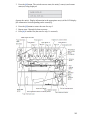
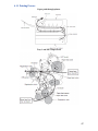
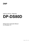
4.1.1 Printing Process
Paper path through printer
Tray 1 and MPT Paper Feed
47
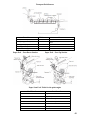
Transport Path Sensors
Location
Reference
Feed (front cover jam)
Transport (paper feed jam)
J5
J6
Exit (paper reject jam)
Tray1 (paper feed jam)
Paper size error (paper size error)
J7
J10
J12
Paper Exit – Face-Down Stacker
Sensor
IN2, WR
IN1, IN2, WR,
EXIT
EXIT
N1
N1
Paper Exit – Face-Up Stacker
Paper Jam Code Table for the print engine
Code Number
Jam Location
370
Duplex reversal
371
Duplex input
372
Feed error at Duplex
373
Multi-feed in Duplex Unit
380
Feed
381
382
Transport
Exit
48
Code Number
Jam Location
383
Duplex entry
385
Around Fuser Unit
390
Feed error at front feeder
391
Tray1
392
Tray2
400
Paper size error
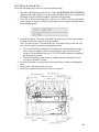
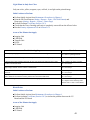
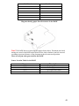
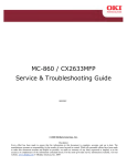
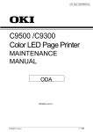
Diagram showing paper detection sensors in the RADF
Note! The RADF detects a jam using the sensors shown above. Document jam check
timings are stored in the ROM on the Main PCB to check whether a jam has occurred
according to presence/absence of the document at the relevant sensor position.
There are no jam codes generated for the RADF
Sensor Location Table for the RADF
Sensor
Description
PI 11
PI 12
PI 13
PI 14
Regist paper sensor
Reverse paper sensor
Cover open/close sensor
Document set sensor
49
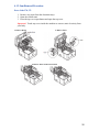
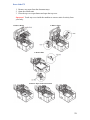
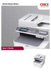
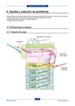
4.1.2 Jam Removal Procedure
Error Code 370, 371
1. Remove any paper from the document trays.
2. Open the scanner unit.
3. Press the top cover open button and open the top cover.
Important! Touch any screw inside the machine to remove static electricity from
your body.
1. Remove Drum
2. Remove Fuser
4. Remove Paper in directions shown
50
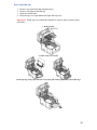
Error Code 372
1. Remove any paper from the document trays.
2. Open the scanner unit.
3. Press the top cover open button and open the top cover.
Important! Touch any screw inside the machine to remove static electricity from
your body.
1. Remove Drum
2. Remove Fuser
3. Remove Belt
4. Remove Paper in directions shown
51
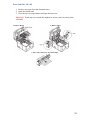
Error Code 380, 390
1.
2.
3.
4.
Remove any paper from the document trays.
Remove any paper in the MP tray.
Open the scanner unit.
Press the top cover open button and open the top cover.
Important! Touch any screw inside the machine to remove static electricity from
your body.
1. Remove Drum
2. Gently remove by top edge
3. If the top edge of the paper cannot be seen, slowly pull out the paper with by the bottom edge.
52
Error Code 381, 382, 385
1. Remove any paper from the document trays.
2. Open the scanner unit.
3. Press the top cover open button and open the top cover.
Important! Touch any screw inside the machine to remove static electricity from
your body.
1. Remove Drum
2. Remove Fuser
3. Press jam release lever & remove Paper
53
Error Code 389
1. Remove any paper from the document trays.
2. Open the scanner unit.
3. Press the top cover open button and open the top cover.
Important! Touch any screw inside the machine to remove static electricity from
your body.
1. Remove Drum
2. Remove Paper in directions shown
54
Error Code 391, 392
1. Remove Cassette
2. Remove Paper
Document Jam (Duplex Path)
1. Open ADF cover to remove paper
Document Jam (ADF)
1. Open ADF cover
3. Check under paper guide
2. Remove paper by top edge
4. Check under document tray
55
Chapter 5 Troubleshooting Error Codes
Troubleshooting Self Diagnostic Codes
Self Diagnostic Error Codes
Cause/Description
Code
Remedy
Machine Check Exception
A hardware error was detected (board failure or insufficient power
supply capacity).
Replace the CU/PU board.
CPU Exception
Remove any RAM DIMM and turn off and on the MFP.
Replace the CU/ PU board.
Reinstall the RAM DIMM.
020
CU ROM Hash Check Error
Turn off and on the MFP.
Replace the CU/ PU board.
030
CU RAM Check Error
Turn off and on the MFP.
Replace the CU/ PU board.
CU Optional RAM Check Error
Is RAM DIMM installed properly?
Reinstall the RAM DIMM.
Replace the RAM DIMM.
Replace the CU/ PU board.
040
CU EEPROM Error
Turn off and on the MFP.
Replace the CU/ PU board.
041
CU FLASH Error
CU PCB FLASH ROM Error
Turn off and on the MFP.
Replace the CU/PU Board
Flash memory file system error
Accessing the flash ROM directly mounted on the CU/ PU board
failed.
Turn off and on the MFP.
Replace the CU/ PU board.
Image processor driver error
Turn off and on the MFP.
Replace the CU/ PU board.
001
002 - 011
031 / 036
042 - 045
052
054
055
057
058
A communication error of the scanner unit
A communication error was detected between the Controller and
scanner unit.
A communication error of the scanner unit
The Controller detected an error after communication between the
Controller and scanner unit was established.
The timeout of command communication of the scanner
The timeout of command communication was detected between the
Controller and scanner unit (A sub code indicates a cause).
01: There is no ACK for a command to start scanning.
02: There is no ACK for a command to cancel scanning.
03: There is no ACK for a command to cancel SIP.
An error of the scanner controlling area
An internal error was detected in the scanner controlling area of the
Controller.
Record a value displayed far right at the bottom of LCD and turn on the
power unit again.
Call for service to review the connection between the scanner and printer
or to replace the device if the symptom persists after you turn on the
power unit again.
Record a value displayed far right at the bottom of LCD and turn off/on
the power unit.
Record a value displayed far right at the bottom of LCD and turn off/on
the power unit.
059
A communication error of the scanner unit
The scanner unit detected an error after communication between the
Controller and scanner unit was established.
Call for service to review the connection between the scanner and printer
or to replace the device if the symptom persists after you turn on the
power unit again.
064
SD Card Missing Error
Is a SD Card installed in the unit, properly?
Power unit off and reinstall SD card.
Replace SD Card.
Replace CU/PU board.
Interface monitor error
Turn off and on the MFP.
Replace the CU/ PU board.
069
NIC Chip Error
Turn off and on the MFP.
Replace the CU/ PU board..
070
Postscript core error
Error is detected inside the postscript core.
Take note of the address that is displayed on LCD.
Turn off and on the MFP.
072
Engine interface error or PU-CU interface error
Is the CU/PU board installed properly?
Reinstall the CU/ PU board properly.
Replace the CU/ PU board.
067 - 068
56
Code
073
074 – 075
081
Cause/Description
Remedy
Video error
An error was detected in expanding image data (an invalid data
was received)
Change the PC to a high-specification one or decrease the resolution, and
perform printing again.
Reinstall the printer driver.
Perform printing again.
Print other data.
Replace the CU/PU board.
Video Error
An error was detected in expanding image data.
Decrease resolution, and execute printing again.
Replace the CU PCB
Parameter matching check error
Reading from or writing into EEPROM or flash memory cannot be
made properly.
Turn off and on the MFP.
Replace the CU/PU board when the symptom persists
Turn off and on the MFP.
Replace the CU/ PU board.
Turn off and on the MFP.
Replace the CU/ PU board.
104
An engine EEPROM read/write error was detected.
106
Engine control logic error.
111
Duplex unit for a different model was detected
Install the correct Duplex unit.
112
The 2nd tray for a model different from the MFP was detected.
Install the correct 2nd tray.
113
The 3rd tray of another model is detected.
Install the correct 3rd tray.
121
High-voltage power supply interface error
Is the cable between the CU/ PU board and the high-voltage power
unit connected properly?
Is a contact faulty?
Reconnect it properly.
Check the high-voltage line for no poor connection.
Replace the high- voltage power supply.
122
Rear-fan error
Does the fan at the rear of the MFP operate?
Is the connector of the fan connected properly?
Be sure of the connection of the fan.
Connect the fan properly.
Replace the CU/PU board.
123
124
126
Ambient humidity error or non connection of humidity sensor
Is the cable from the CU/PU board to the toner sensor board
connected properly?
Ambient temperature error
Is the cable from the CU/PU board to the toner sensor board
connected properly?
Condensation on the device was detected.
Condensation is likely to form in such a case that a device is carried
in from the outdoors.
Leave the device untouched for two hours to a half day and turn on
the power unit.
Re-connect it properly.
Replace the toner sensor board.
Re-connect it properly.
Replace the toner sensor board.
Leave the device untouched and turn on the power unit.
Replace a control panel board.
127
An error of exhaust fan of the Fuser
Is the fan's connector properly connected?
Connect properly.
Replace the fan's motor.
Replace the CU/PU board.
128
05: Image drum fan error
07: Front fan error
Is the connector of the fan connected properly?
Re-connect it properly
Replace the fan motor.
Replace the CU/PU board.
131 – 134
142
LED head detection error
131=Y
132=M
133=C
134=K
Is the LED head installed properly?
Is the LED head fuse broken?
Image drum up-down movement position detection error
Is the image drum unit removed and installed smoothly?
Is the connector of the image drum up-down clutch is connected
properly?
153
Image drum unit fuse-cut error
Is the image drum unit installed properly?
154
Belt unit fuse-cut error
Is the belt unit installed properly?
Install the LED head unit.
Check the LED head fuse. (For the fuse check method, refer to section
2.8.11.)
Turn off and on the MFP.
Replace the LED head unit.
Replace the CU/PU board.
Be sure of the connection of the image drum up-down clutch connector.
Replace the toner sensor board.
Connect the image drum up/down clutch properly.
Re-install image Drum Unit.
Turn off and on the MFP.
Be sure of the cable connection from the CU/PU board to the toner sensor
board, and then replace the toner sensor board.
Replace the CU/PU board.
Re-install Transfer Belt Unit.
Turn off and on the MFP.
Be sure of cable connection, and then replace the CU/PU board.
57
Cause/Description
Code
155
160 – 163
Fuser unit fuse-cut error
Is the fuser unit installed properly?
Toner sensor detection error
160=Y,
161=M,
162=C,
163=K).
This error does not occur with the MFP in the factory shipped
configuration.
Install the toner cartridge.
Turn it to the fixed (locked) position.
Turn off and on the MFP.
Replace the toner sensor assembly.
167
Thermistor slope error
168
Compensation thermistor error
169
An error of the Upper Side Thermistor
170 – 171
A fuser thermistor short or open circuit was detected.
172 – 173
A fuser thermistor temperature error (high or low temperature) was
detected.
174
A backup thermistor shot circuit was detected (high temperature)
175
A backup thermistor open circuit was detected (low temperature)
176 – 177
Remedy
Clean the connection connector of the fuser unit, and then re-install the
fuser unit.
Turn off and on the MFP.
Be sure of cable connection, and then replace the CU/PU board.
A backup thermistor temperature error (high or low temperature) was
detected.
Turn off and on the MFP.
Turn off and on the MFP after leaving it for 30 minutes.
Turn off and on the MFP.
Turn off and on the MFP after leaving it for 30 minutes.
Turn off and on the MFP.
Turn off and on the MFP after leaving it for 30 minutes.
After cleaning the connectors of the Fuser, re-install it.
Turn off and on the MFP.
Replace the fuser unit.
After cleaning the connectors of the Fuser, re-install it.
Turn off and on the MFP.
Replace the fuser unit.
Replace the low-voltage power supply.
Replace the CU/PU board.
Turn off and on the MFP.
Replace the fuser unit.
Turn off and on the MFP.
Replace the fuser unit.
Turn off and on the MFP.
Replace the fuser unit.
Replace the Low Voltage Power Supply.
Turn off and on the MFP.
Be sure of connector connection.
Replace the option unit.
182
Option unit I/F error
190
System memory overflow
Turn off and on the MFP.
Replace the CU/PU board.
200 – 202
PU firmware download error
An error occurred in re-writing the PU firmware.
Turn off and on the MFP, and then re-download it (In general use of the
MFP, this re-writing is not performed and this error does not occur)
203 – 208
213 – 214
F0C
FFE
FFF
CU program error (203 to 214 do not occur in general use of the
MFP)
Invalid processing was performed with a CU program.
Replace the CU/PU board.
209
Custom Media Type table downloading failure
Custom Media Type table downloading failed.
Turn off and on the MFP, and then re-download it (In general use of the
MFP, this downloading is not performed and this error does not occur)
231
TAG interface error
IA TAG interface error was detected.
01 : A short-circuit error.
03 : TAG communication error.
Be sure the toner cartridges and the image drums are properly set.
Replace the toner cartridges.
When the error occurs again after the image drums are re-installed, be
sure of the cable connection from the CU/PU board to the toner sensor
board.
250
SD card error
251
SD card erasure error
252 – 255
SD card security error
256 – 257
SD card error
58
Cause/Description
Code
Remedy
802 – 803
805
807
808
SU Exception
Turn off and on the MFP.
Replace the SU board.
811 – 813
SU Communication Error
Communication error between the Controller and the Scanner Unit is
detected.
Turn off and on the MFP.
SU System Memory Overflow
Turn off and on the MFP.
Replace the SU board.
Belt temperature error
901: Short circuit
902: Open circuit
903: High temperature
904: Low temperature
Is the cable from the belt thermistor to the CU/PU board connected
properly?
Connect the cable properly.
Turn off and on the MFP.
Replace the belt thermistor.
890
901 – 904
918
An alarm of Duplex Fan was detected.
An error of a fan inside the Duplex.
923
A lock error with black image drum
The image drum does not revolve properly.
928
Fuser motor lock error
933
Tray-2 CPU clock frequency error
941 – 944
980
983
990
PU Error
A PU error was detected.
941 : Watch Doc Timer Error
942 : Detection of Unassigned Interruption
943 : CPU Error Detection
944 : Dcon Access Error
Media jamming error around fuser
Media is jammed by entangling around the fuser.
Duplicate toner cartridge detection error
Multiple toner cartridges for the same color were detected.
Waste toner sensor detection error
Review whether or not the Duplex is installed properly.
Review whether or not the fan is installed properly.
Replace the fan
Be sure the image drum is properly installed properly.
Replace the image drum unit.
Replace the image drum motor.
Check that the fuser is properly installed.
Replace the fuser.
Replace the fuser motor.
Turn off and on the MFP.
When this error occurs again, replace the CU/ PU board.
Turn off the MFP.
Replace the fuser.
Install toner cartridges for specified colors at the proper positions
Install the K toner cartridge.
Be sure of cable connection, and then perform board replacement.
Note! With the MFP’s temperature not more than 0ºC, Service call errors 168 Error, 171 Error, 175 Error,
903 Error and 904 Error may occur. After turn off the MFP, turn on the MFP after the MFP warms.
59