1
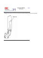
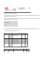
Thank You for purchasing this
Factory Service Manual on EBAY
from PCTECHINFO!
Click Here for more Factory Service
Manuals for other Computer and
Printer / Copier Manufacturers
from PCTECHINFO!
C7000 Series Color LED
Page Printer
SERVICE
MANUAL
This manual describes the procedures for the maintenance of the C7000 Series of printers.
The document is produced for maintenance personnel use. For details on the procedures for
handling the C7000 Series of printers, see its user documentation.
Table of Contents
Page
Service Guide - C7000 Series
Preface
1 Specifications
1.1 System Configuration
1.2 Printer Configuration
1.3 Option Configuration
1.4 Specifications
2 Operation
2.0 Operation
2.1 Main board (CRM PWB)
2.2 Engine Controller Board (K71 PWB)
2.3 Power Units
2.4 Mechanical Processes
....2.4.1 Electrphotographic process
........(1) Electrophotographic processes
........(2) Charging
........(3) Exposure
........(4) Developing
........(5) Transfer
........(6) Fusing
........(7) Cleaning - waste toner area
........(8) Cleaning - transfer belt
....2.4.2 Paper running process
........(1) Paper Feed from Tray
........(2) Paper Feed from Multi-Purpose Tray (MT)
........(3) Transport Belt
........(4) Driving and Up-and-Down Movements of I/D Unit
........(5) Fuser Unit and Paper Ejection
........(6) Duplex Unit
2.5 Sensor
....2.5.1 Paper related sensors
....2.5.2 Other sensors
2.6 Color Misalignment Correction
2.7 Transfer control Responds to Environmental Changes
(Room Temperature and Relative Humidities)
2.8 Paper Jam Detection
2.9 Cover-Open
2.10 Toner Low Detection
2.11 Page Size Detection
2.12 Operation at Power-on
2.13 Color Misalignment Detection
2.14 Version Read of Units Replaced Periodically
2.15 Life Count for Units Replaced Periodically
2.16 Toner Consumption Detection
3 Disassembly
1
2
3
4
5
6
7
8
9
10
11
12
13
14
15
16
17
18
19
20
21
22
23
24
25
26
27
28
29
30
31
32
33
34
35
36
37
38
39
40
Table of Contents
3.0 Precaution in Replacing Parts
3.1 Precaution in Replacing Parts
3.2 Parts Layout
....Top Cover Assy
....Printer Unit
....Cassette Guide Assy (L), (R)
....Duplex Unit
3.3 Replacing Parts
....3.3.1 Top Cover
....3.3.2 LED Assy / LED Assy Spring
....3.3.3 Top Cover Unit
....3.3.4 Control Panel Assy / Control Panel Bezel / LED Control
PWB / Toner Sensors / Stacker Full Sensor / Control Panel /
Control Panel Tape Harness / Eject Rollers
....3.3.5 Top Cover Handle / Top Cover Latch / Top Cover
Latch Spring
....3.3.6 Eject Guide Assy
....3.3.7 Cassette Assy / Front Cover Assy / Front Cover Inner
Baffle
....3.3.8 Retard Pad Assy / Retard Pad Assy Spring
....3.3.9 Feed Roller and Nudger Roller
....3.3.10 Rear Cover
....3.3.11 Face-Up Tray
....3.3.12 Left Side Cover
....3.3.13 Right Side Cover
....3.3.14 Multi-purpose Tray Assy / Links
....3.3.15 Drum Contact Assys
....3.3.16 Registration Roller Assy (A) / Registration Drive Gear
(A)
....3.3.17 Registration Roller Assy (B)
....3.3.18 Registration Clutch and Registration Motor Assy
....3.3.19 Main Cooling Fan
....3.3.20 Color Registration Sensor Assy
....3.3.21 Duplex Guide Assy
....3.3.22 Electrical Chassis Cooling Fan
....3.3.23 Printer Engine Controller PWB
....3.3.24 Printer Unit Chassis
....3.3.25 Entrance Cassette Sensor Actuator
....3.3.26 Entrance Sensor PWB
....3.3.27 Entrance MT Sensor Actuator and Entrance Belt
Sensor Actuator
....3.3.28 Fuser Exit Roller
....3.3.29 Exit Sensor Assy
....3.3.30 Fuser Latching Handle (L)
....3.3.31 Belt Motor Assy
Page
41
42
43
44
45
46
47
48
49
50
51
52
53
54
55
56
57
58
59
60
61
62
63
64
65
66
67
68
69
70
71
72
73
74
75
76
77
78
79
Table of Contents
....3.3.32 Fuser Latching Handle (R)
....3.3.33 Main Motor Assy
....3.3.34 Main Feeder Drive Motor
....3.3.35 Contact Assy / Left Plate Assy
....3.3.36 Low Voltage Power Supply
....3.3.37 High Voltage Power Supply
....3.3.38 Main Feed Assy
....3.3.39 Cassette / Left Guide Assy
....3.3.40 Cassette / Right Guide Assy
....3.3.41 Fuser Unit
....3.3.42 Belt Unit
....3.3.43 Duplex Unit
....3.3.44 Guide Rails (L) and (R)
....3.3.45 Duplex Transport Assembly
....3.3.46 CU Assy
4 Adjustments
4.0 Adjustments
4.1 Maintenance Modes and Their Functions
....4.1.1 Maintenance Menu
....4.1.2 Engine maintenance mode
........4.1.2.1 Operator panel
........4.1.2.2 General self-diagnosis mode (level 1)
............4.1.2.2.1 Entering self-diagnosis mode (level 1)
............4.1.2.2.2 Exiting self-diagnosis mode
........4.1.2.3 Switch scan test
........4.1.2.4 Motor and clutch test
........4.1.2.5 Test printing
........4.1.2.6 NVM initialization
........4.1.2.7 Consumable Counter Display
........4.1.2.8 Consumable Counter Display - Continuos
........4.1.2.9 Error Messages and their Details
....4.1.3 CRM board adjustments
........4.1.3.1 Short plug settings
........4.1.3.2 Printing Menu Reports
4.2 Adjustments after Parts Replacement
....4.2.1 Precautions in replacing engine controller board
....4.2.2 Precautions in replacing EEPROM
....4.2.3 EEPROM replacement after CRM board replacement
4.3 Color Balance Adjustment
5 Period Maintenance
5.0 Periodic Maintenance
5.1 Parts Replaced Periodically
5.2 Cleaning
5.3 Cleaning LED Lens Array
5.4 Cleaning Pickup Roller
Page
80
81
82
83
84
85
86
87
88
89
90
91
92
93
94
95
96
97
98
99
100
101
102
103
104
105
106
107
108
109
110
111
112
113
114
115
116
117
118
119
120
121
122
Table of Contents
6 Troubleshooting Procedures
6.1 Before Troubleshooting
6.2 Checking before Troubleshooting Image Problems
6.3 Precautions in Troubleshooting Image Problems
6.4 Preparation for Troubleshooting
6.5 Troubleshooting
....6.5.1 LCD messages list
........Table 6-1-1 Operator Alarms (1/2)
....6.5.2 LCD Preparation for Troubleshooting
........(1) The printer does not operate properly after power-on.
........(2) Jams
............(2)-1 Paper Loading Jam (1st Tray)
............(2)-2 Paper Loading Jam (Multi-Purpose Tray)
............(2)-3 Paper feed jam
............(2)-4 Paper Exit Jam
............(2)-5 Duplex Jam
........(3) Paper Size Error
........(4) Image Drum Unit (ID) Up-and-Down Operation Error
........(5) Fusing Unit Error
........(6) Motor Fan Error
....6.5.3 Troubleshooting image problems
........(1) Light or Faded Image on Whole Page, or Color
Misalignment on Whole Page (Figure 6-2 A)
........(2) Dirty Background (Figure 6-2 B)
........(3) Blank Page (Figure 6-2 C)
........(4) Vertical Belt or LIne (Black or Color Belt, or Black or
Color Line) (Figure 6-2 D)
........(5) Vertical White Belt or Line, or Uneven-Color Belt or
Line (Figure 6-2 F)
........(6) Poor Fusing (Ink spreads or peels when touched with
fingers)
........(7) Defective Image of Regular Interval (See Figure 6-2 E)
........(8) Missing Image
........(9) Color Misalignment
........(10) Color Different from Original One
........Figure 6-3
7 Wiring Diagram
7.1 Resistance Check
7.2 Program/Font ROM Location
8 Parts List
Main Assembly - Figure 8-2
Main Assembly - Table 8-1 (1/3)
Main Assembly - Table 8-1 (2/3)
Main Assembly - Table 8-1 (3/3)
Top Cover Assembly - Figure 8-2
Page
123
124
125
126
127
128
129
130
131
132
133
134
135
136
137
138
139
140
141
142
143
144
145
146
147
148
149
150
151
152
153
154
155
156
157
158
159
160
Table of Contents
Top Cover Assembly - Table 8-2
Printer Unit Chassis Figure 8-3
Printer Unit Chassis - Table 8-3
Paper Tray Guide - Figure 8-4
Paper Tray Guide - Table 8-4
Duplex Unit - Figure 8-5
Duplex Unit - Table 8-5
Centronics Parallel Interface
B 2nd/3rd Tray Maintenance
1. Parts Replacement
....1.1 Cover Idle Roller Assy
....1.2 PCB
....1.3 Feeder Drive Assy
2. C7000 2nd/3rd Tray Parts List
........Table 6-1-1 Operator Alarms (2/2)
Page
161
162
163
164
165
166
167
168
169
170
171
172
173
174
Service Guide - C7000 Series
Page: 1
Chapter 0 Introduction
Preface
This manual describes the procedures for the maintenance of the C7000 Series of printers.
The document is produced for maintenance personnel use. For details on the procedures for handling the C7000 Series of printers, see its user documentation.
Notes!
l
The descriptions in this manual are subject to change without prior notice.
l
In preparing the document, efforts have been made to ensure that the information in it is accurate. However, there may be errors in the document. Oki
Data assumes no responsibility for any damage resulting from, or claimed to be the results of, those repairs, adjustments or modifications to the printers
which are made by users using the manual.
l
The parts used for the printers are electrostatic sensitive and, if handled improperly, may be damaged. It is strongly recommended that the products be
maintained by Oki Data Authorized Repair Centers Oki Data.
Copyright 1999, Okidata, Division of OKI America, Inc. All rights reserved.
Service Guide - C7000 Series
Chapter 1 Specifications
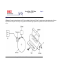
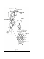
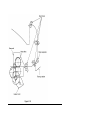
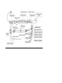
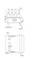
1.1 System Configuration
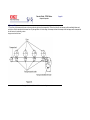
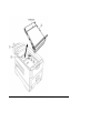
Figure 1-1 shows the system configuration of the C7000 Series of printers.
Page: 2
Copyright 1999, Okidata, Division of OKI America, Inc. All rights reserved.
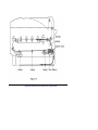
Service Guide - C7000 Series
Chapter 1 Specifications
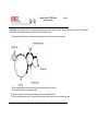
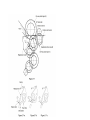
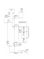
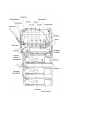
1.2 Printer Configuration
The inside of the printer is composed of the following:
l
Electrophotographic Processor
l
Paper Paths
l
Controller Block (CU and PU)
l
Operator Panel
l
Power Units (High Voltage Unit and Low Voltage Unit)
Figure 1-2 shows the printer configuration.
Page: 3
Copyright 1999, Okidata, Division of OKI America, Inc. All rights reserved.
Service Guide - C7000 Series
Chapter 1 Specifications
1.3 Option Configuration
The following options are available for the C7000 Series of printers.
(1)
2nd Tray / 3rd Tray
(2)
Duplex Unit
(3)
Expansion Memory
64/128/256 MB
Page: 4
(4)
Internal Hard Disk
(5)
OkiLAN 6200e NIC
Copyright 1999, Okidata, Division of OKI America, Inc. All rights reserved.
Service Guide - C7000 Series
Chapter 1 Specifications
1.4 Specifications
(1)
External Dimensions
Height: 16.9 in. Width: 16.9 in. Length: 24.4 in.
(2)
Weight
92.5 lbs.
(3)
Papers
Type: Ordinary paper, Transparencies
(Recommended: MLOHP01)
Size: Postal card, Legal 13" or 14", Executive, A4,
A5, B5, A6 (Only
the 1st tray and the front feeder support A6 and
postal-card
sizes.)
Weight: 1st tray 55 kg to 90 kg (64 to 105g/m 2 )
Front feeder 55 kg to 140 kg (64 to 163g/ m 2 )
(4)
Print Speed
Color: 12 pages per minute (Transparency: 5 pages
per minute)
Monochrome: 20 pages per minute (Transparency:
12 pages per minute)
Postal Card, Label, Thick Paper: 8 pages per minute
(5)
Resolution
(C7200) = 600 × 600 -//- (C7400) 1200 x 1200 dots
per inch
(6)
Power Input
100VAC ±10%
(7)
Power Consumption
Peak: 1300W Normal Operation: 400W (5% duty)
Idle: 110W Power Saving Mode: 45W or less
(8)
Frequency
50Hz or 60Hz ±2%
(9)
Noise
Operation: 54 dB (Without second tray)
Standby: 45 dB
Power Saving: 43 dB
(10)
Consumable Life
Toner Cartridge: 10,000 pages (5% duty) (each of Y,
M, C and K)
Page: 5
Image Drum: 30,000 pages (Continuous printing)
(each of Y, M, C and K)
(11)
Parts Replaced Periodically
(12)
Temperatures and Relative
Humidities
Fuser Unit Assy: Every 60,000 pages
Transfer Belt Assy: Equivalent of 60,000 pages (3
pages/job)
Temperature
Fahrenheit
Operating
Non-operating
Storage (1 year max.)
Delivery (1 month max.)
Delivery (1 month max.)
Temperature conditions
Celsius
Remarks
50 to 89.6
10 to 32
32 to 109.4
-14 to 109.4
-20 to 122
-20 to 122
0 to 43
-10 to 43
-29 to 50
-29 to 50
17 to 27 Celsius (Temperatures to assure
full color print quality)
Power off
with drum and toner
with drum and without toner
with drum and toner
Humidity
Fahrenheit
Humidity condition
Celsius
Remarks
Operating
20 to 80
25
Non-operating
Storage
Delivery
10 to 90
10 to 90
10 to 90
26.8
35
40
(13)
Printer Life
50% to 70% (for assurance of full-color
printout quality)
Power off
600,000 pages (on a A4-size basis) or five years
Copyright 1999, Okidata, Division of OKI America, Inc. All rights reserved.
Service Guide - C7000 Series
Page: 6
Chapter 2 Operation
2.0 Operation
The C7000 Series of printers, tandem color electrophotographic page printers, adopt technologies such as an LED array, OPC, dry single-component
non-magnetic developing, roller transfer and heat-compression fusing. A black-writing printing method by shedding light on print areas is used.
Copyright 1999, Okidata, Division of OKI America, Inc. All rights reserved.
Service Guide - C7000 Series
Chapter 2 Operation
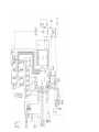
2.1 Main board (CRM PWB)
Figure 2-2 provides the block diagram of the main control board (CRM PWB).
Page: 7
(1)
CPU
The CPU is PowerPC750, a 64-bit bus RISC processor, which inputs an 80-MHz CLK
(=BUS CLK), and operates at 400MHz that is five times the input.
(2)
Secondary Cache SRAM
SRAM is included as secondary cache of the CPU on the board.
(3)
ROM
ROM is to be inserted into the three 168 pin DIMM slots. The slot A is for program ROM
and the slot B is for Japanese kanji fonts. The slot C is not assigned.
(4)
RAM
RAM is to be inserted into the four 168 pin DIMM slots. The DIMMs must be fitted in
descending labeled type No. order into the slots 1, 3, 2 and 4.
SDRAM DIMM Specifications:
Speed: PC100 or more
Capacity: 64/128/256 MB
Configuration: Without parity. Without ECC. SPD information is required. Number of chips
contained = 8 or 16.
(5)
EEPROM
EEPROM, an 8-pin DIP package, is to be inserted into the IC socket. The EEPROM is of
16 Kbits for 3.3V power supply, and settings for controlling the controller block are stored
in it.
(6)
Flash ROM
A 2-Mbyte flash ROM is surface-mounted on the CRM board. The flash ROM is
composed of four 256-k-by-16bit chips, and fonts and macros can be stored in it.
(7)
Memory control LSI (CI)
A 696-pin BGA package ASIC made by NEC, which is equipped with a cooling heat sink
and mainly controls a CPU I/F, memory, video data compression and decompression,
and a PU-video I/F.
(8)
Interface control LSI (C2)
A BGA package ASIC made by Toshiba, which controls a PU command I/F, operator
panel I/F, IDE I/F, Centronics I/F, USB I/F, PCI I/F, EEPROM and a SPD (SDRAM DIMM)
I/F.
(9)
IDE HDD
An IDE connector is surface-mounted on the board to which an IDE HDD assembled
using
Additional Board: (connected to PCI BUS) / Ethernet Board
Copyright 1999, Okidata, Division of OKI America, Inc. All rights reserved.
Service Guide - C7000 Series
Chapter 2 Operation
2.2 Engine Controller Board (K71 PWB)
Page: 8
The engine control block (PU) is controlled by the engine controller board (K71 PWB) which consists of a CPU (MSM66Q577), general LSI chip, flash ROM,
EEPROM, pulse motor drivers and a video memory (see Figure 2-4).
(1) CPU
This, a 16-bit CPU with an AD converter containing 126-Kbyte ROM (OKI MSM66Q577), controls the entire system.
(2) General LSI
This LSI (MG63P011-001LA), which is contained in the printer engine control block, has 4 Mbits of video memory, and functions such as controller-engine video
interfacing, LED interfacing, motor control, sensor input, video memory control, main scan color misalignment correction, skew correction and high voltage power
supply control.
(3) Flash ROM
The flash ROM (29F400-70) is of 4-Mbits, and PU programs are stored in it.
(4) EEPROM
The EEPROM (NM93C66N-NW) is of 4-Kbits, and mounted on the board with an IC socket. Correction values are stored in it.
(5) Pulse Motor Driver
The pulse motor driver (A2919SLBTR, A2918SWV) drives the eight pulse motors to revolve the EP and transport media.
(6) SRAM
This SRAM (62256LFP-7LL) is used as working memory of the CPU.
Copyright 1999, Okidata, Division of OKI America, Inc. All rights reserved.
Service Guide - C7000 Series
Page: 9
Chapter 2 Operation
2.3 Power Units
There are a low voltage power unit consists of an AC filter circuit, low voltage power circuit and heater driver circuit, and a high voltage power unit organizes a
high voltage power circuit.
(1) Low voltage power supply circuit.
This circuit generates the following voltages.
Output voltage
+3.8 V
+3.8 V
+5 V
+34 V
-12 V
Use
CU LSI
LED head
Logic circuit power supply, PU CPU
Motor, drive voltage and power supply voltage for high voltage power
supply
OP Amp, High voltage power supply
(2) High voltage power supply circuit
This circuit generates the following voltages of not less than +34V, which are required for electrophotographic process, according to control sequences from the
controller board.
Output
CH
DB
SB
TR
Voltage
-900V to 1.4KV
-100 to 400V/ +300V
Y, M, C, and K:
-100V to -700V
0Kv to 7KV
Use
Remarks
Voltage to charging roller
Voltage to developing roller
Voltage to toner supply roller
Voltage to transfer roller
Variable
Copyright 1999, Okidata, Division of OKI America, Inc. All rights reserved.
Service Guide - C7000 Series
Chapter 2 Operation
2.4 Mechanical Processes
Figure 2-4 shows the mechanical processes of the C7000 Series of printers.
Page: 10
Copyright 1999, Okidata, Division of OKI America, Inc. All rights reserved.
Service Guide - C7000 Series
Chapter 2 Operation
2.4.1 Electrphotographic process
(1)
Electrophotographic processes
(2)
Charging
(3)
Exposure
(4)
Developing
(5)
Transfer
(6)
Fusing
(7)
Cleaning - waste toner area
(8)
Cleaning - transfer belt
Copyright 1999, Okidata, Division of OKI America, Inc. All rights reserved.
Page: 11
Service Guide - C7000 Series
Chapter 2 Operation
(1) Electrophotographic processes
(1)
Electrophotographic processes - The following is the outline of electrophotograhic
process:
(1) Charging - DC voltage is applied to the charging roller and the surface of the OPC
drum is negatively and evenly charged.
(2) Exposure - The LED head, under image signals, emits light to the negatively charged
surface of the OPC drum. The radiated portions of the drum surface attenuate in negative
charge according to the intensity of the light and, based on the surface potentials, a latent
electrostatic image is formed on the drum surface.
(3) Development - Negatively charged toner contacts the OPC drum and by electrostatic
force adheres to the latent electrostatic image to form a clear image on the drum surface.
(4) Transfer - Placed on the surface of the OPC drum, paper is positively, or opposite to
the polarity of the toner, charged by the transfer roller on its back to transfer the toner
image to the paper.
(5) Cleaning - The cleaning blade removes residual toner from the OPC drum after the
transfer.
(6) Fusing - The toner image on the paper is fused into place through the application of
heat and pressure to it.
Copyright 1999, Okidata, Division of OKI America, Inc. All rights reserved.
Page: 12
Service Guide - C7000 Series
Chapter 2 Operation
(2) Charging
(2)
Charging - Negative DC voltage is applied to the charging roller contacting the surface of
the OPC drum.
Copyright 1999, Okidata, Division of OKI America, Inc. All rights reserved.
Page: 13
Service Guide - C7000 Series
Page: 14
Chapter 2 Operation
(3) Exposure
(3) Exposure - The negatively charged surface of the OPC drum is radiated with light from the LED head. The negative charge of the radiated portions of the drum
surface attenuates in response to the intensity of the light and a latent electrostatic image responsive to the potentials of the surface is formed on the drum
surface.
Copyright 1999, Okidata, Division of OKI America, Inc. All rights reserved.
Service Guide - C7000 Series
Page: 15
Chapter 2 Operation
(4) Developing
(4) Developing - By the adhesion of toner to the latent electrostatic image on the drum surface, the image is changed to an image of its toner. The development
is processed at the contact portion between the OPC drum and the developing roller.
(1) The sponge roller causes toner to adhere to the developing roller. The toner becomes negatively charged.
(2) The developing blade removes excess toner from the developing roller and a thin layer
of toner remains and forms on the developing roller.
(3) The toner is drawn by the latent electrostatic image at the contact portion between the
OPC drum and the developing roller. The latent electrostatic image on the drum surface is made visible with the toner.
Copyright 1999, Okidata, Division of OKI America, Inc. All rights reserved.
Service Guide - C7000 Series
Page: 16
Chapter 2 Operation
(5) Transfer
(5) Transfer - The transfer roller, which is made of conductive sponge, presses paper against the surface of the OPC drum and brings the paper into intimate
contact with the drum surface. The paper is placed on the drum surface, and positively (opposite to the charge of the toner) charged by the transfer roller on its
back.
Applying positive high voltage from the power supply to the transfer roller moves the positive charge induced by the transfer roller to the paper surface at the
contact portion between the transfer roller and the paper, the paper surface drawing the negatively charged toner from the drum surface.
Copyright 1999, Okidata, Division of OKI America, Inc. All rights reserved.
Service Guide - C7000 Series
Page: 17
Chapter 2 Operation
(6) Fusing
(6) Fusing - When passing through between the heat roller and the backup roller, the toner image transferred to the paper is fused into place by the application
of heat and pressure to it. The built-in upper and lower halogen lamps of 700 watts and 500 watts heat the Teflon coated heat roller. The fusing temperature is
controlled by the sum of the temperature detected by the thermistor moving over the heat roller surface and the temperature detected by the
thermistor moving over the backup roller surface. For safety, a thermostat is provided and, when the heat roller temperature rises by a fixed degree or more,
becomes open to cut off voltage supply to the heater. The backup roller is being pressed against the heater by the pressure springs on both sides.
Copyright 1999, Okidata, Division of OKI America, Inc. All rights reserved.
Service Guide - C7000 Series
Page: 18
Chapter 2 Operation
(7) Cleaning - waste toner area
(7) Cleaning - Non-fused, residual toner on the OPC drum is scraped with the cleaning blade and collected in the waste toner area of the toner cartridge.
Copyright 1999, Okidata, Division of OKI America, Inc. All rights reserved.
Service Guide - C7000 Series
Page: 19
Chapter 2 Operation
(8) Cleaning - transfer belt
(8) Cleaning - Residual toner on the transfer belt is scraped with the cleaning blade and collected in the waste toner box of the transfer belt unit.
Copyright 1999, Okidata, Division of OKI America, Inc. All rights reserved.
Service Guide - C7000 Series
Chapter 2 Operation
2.4.2 Paper running process
Figure 2-5 shows the traveling of paper in the C7000 Series of printers.
Page: 20
Copyright 1999, Okidata, Division of OKI America, Inc. All rights reserved.
Service Guide - C7000 Series
Page: 21
Chapter 2 Operation
(1) Paper Feed from Tray
1. The running of the feed motor in the arrow direction (a) drives the feed roller and the nudger roller. This operation feeds paper from the tray.
2. After the beginning of the paper turns the entrance cassette sensor on, the paper is advanced a fixed length. When the paper beginning reaches the
registration roller Assy (A), the feed motor stops.
3. The running of the registration motor in the arrow direction (b), which synchronizes with the above paper advance operation, drives the registration roller Assy
(B) and the electromagnetic clutch. The registration roller Assy (A) moves with the operation of the electromagnetic gear when the paper beginning touches the
registration roller Assy (A),
where the feed motor does not run. The feed roller idles via the built-in one-way clutch and the nudger roller idles because the planet gear is disengaged.
4. The registration motor transports the paper until the paper end passes through the entrance belt sensor.
Copyright 1999, Okidata, Division of OKI America, Inc. All rights reserved.
Service Guide - C7000 Series
Page: 22
Chapter 2 Operation
(2) Paper Feed from Multi-Purpose Tray (MT)
1. The release lever usually pushes down the hopping plate to a position that turns microswitch on (Figure 2-7-a).
2. The running of the motor in the (a) direction drives the MT feed roller and turns the cam. The cam pushes the release lever and the hopping plate picks up
paper sent out by the MT feed roller (Figure 2-7-b), where the registration roller Assy (B) does not move because its one-way clutch gear (1) idles.
3. After the paper beginning turns the entrance sensor on, the paper is forwarded a fixed length. The paper stops when its beginning reaches the registration
roller Assy (B).
4. At the same time, the cam pushes down the hopping plate. The release lever that has been placed in its original position by the spring locks the hopping plate
(Figure 2-7-c).
5. After the completion of the paper feed operation, the registration motor runs in the arrow direction (b) to drive the registration roller Assy (B), where the
one-way clutch gear (2) does not allow the MT feed roller to move.
Copyright 1999, Okidata, Division of OKI America, Inc. All rights reserved.
Service Guide - C7000 Series
Page: 23
Chapter 2 Operation
(3) Transport Belt
1. The running of the transport belt motor in the arrow direction (a) drives the transport belt. The belt unit sits with one transport roller immediately below each
color's drum, and the transport belt between them. By the application of a fixed voltage, the transport belt and the transport roller feed paper on the transport belt
into the fuser unit, transferring a toner
image on each color's drum.
Copyright 1999, Okidata, Division of OKI America, Inc. All rights reserved.
Service Guide - C7000 Series
Page: 24
Chapter 2 Operation
(4) Driving and Up-and-Down Movements of I/D Unit
1. The I/D unit driving and up-and-down movements are effected by a single-pulse motor. The running of the main motor in the arrow direction (a) turns the lever
1 to the left. Then, the lever 2 that was lifted by the lever 1 lowers to move down the I/D unit. After the up/ down sensor is turned off (Figure 2-9-d), specified
downward pulsing places the I/D unit
in its lowest position, or equivalently, printing position (Figures 2-9-a and 2-9-c). The drum gear engages with the driving gear and starts revolving to transfer an
image on the drum to running paper, where the one-way gear idles upon placement of the lever in its lowest position.
2. With the running of the main motor in the arrow direction (b), the lever 1 pushes up the I/ D unit via the lever 2. After the up/down sensor is activated (Figure
2-9-d), the lever 1 lifts the I/D unit to a specified level and stops to keep space to an extent between the drum and the transport belt (Figures 2-9-c and 2-9-e).
The drum gear is not engaged with the driving gear and does not revolve.
3. When the two pins of the up/down sensor are pushed up by the I/D unit, and touches and electrically connected to the plate above the pins, the sensor
recognizes the on state. When the two pins are pushed down by the I/D unit, and separated and insulated from the plate, the sensor recognizes the off state. The
installation of the I/D unit can also be verified by recognizing the off state of the up/down sensor.
Copyright 1999, Okidata, Division of OKI America, Inc. All rights reserved.
Service Guide - C7000 Series
Page: 25
Chapter 2 Operation
(5) Fuser Unit and Paper Ejection
1. A single-pulse motor drives the fuser unit and the eject rollers. In response to the running of the heat motor in the arrow direction (a), the heat roller turns. This
roller fuses a toner image to paper by heat and pressure.
2. At the same time, the four eject rollers move to eject the paper.
3. The ejection path is switched back and forth between the route to the face-up stacker and the route to the face-down stacker as follows. When the face-up
stacker opens, the paper separator inclines in the direction that guides the paper to the face-up stacker. When the face-up stacker closes, the paper separator
inclines in the direction that sends the paper to the face-up stacker.
Copyright 1999, Okidata, Division of OKI America, Inc. All rights reserved.
Service Guide - C7000 Series
Page: 26
Chapter 2 Operation
(6) Duplex Unit
1. When the duplex unit receives an instruction from the printer to print on both sides of a sheet of paper, the solenoid opens the separator after the completion of
one side printing of a sheet of paper sent from the tray. The path is switched to that to the duplex unit. At this time, as the roller (1) turns in the direction of the
arrow "a" the paper is retracted
on the rear of the cassette.
2. When fixed time has elapsed after the paper beginning passes through the duplex-in sensor, the rollers reverse and the roller (1) turns in the direction of the
arrow "b" to feed the paper into the duplex unit. After that, the paper passes through the rollers (2), (3) and (4), and ejected with the other side printed, and fed
again into the printer.
Copyright 1999, Okidata, Division of OKI America, Inc. All rights reserved.
Service Guide - C7000 Series
Chapter 2 Operation
2.5 Sensor
2.5.1 Paper related sensors
2.5.2 Other sensors
Copyright 1999, Okidata, Division of OKI America, Inc. All rights reserved.
Page: 27
Service Guide - C7000 Series
Chapter 2 Operation
2.5.1 Paper related sensors
Sensor
Function
Sensor status
Entrance MT sensor
Entrance Cassette
sensor
Entrance Belt sensor
Detects the beginning of incoming paper to
determine the timing for switching from hopping to
transport.
Detects the beginning of transported paper and,
based on the time taken until the paper beginning
reaches the sensor, determines the paper length.
Detects the beginning and end of paper to determine
the paper ejection timing.
ON: paper is present.
OFF: Paper is absent.
Exit sensor
ON: paper is present.
OFF: Paper is absent.
ON: paper is present.
OFF: Paper is absent.
Page: 28
Duplex in sensor
Duplex Rear sensor
Duplex Front sensor
Stacker Full sensor
Detects the beginning of paper that enters into the
duplex unit, to determine the time taken until the
reversed rollers turn in forward direction.
Detects the beginning of reverses paper in the
duplex unit.
Detects the end of reversed paper in the duplex unit
to determine the paper ejection timing.
Detects the face-down stacker full of paper.
ON: paper is present.
OFF: Paper is absent.
ON: paper is present.
OFF: Paper is absent.
ON: paper is present.
OFF: Paper is absent.
ON: Stacker is full.
OFF: Stacker is empty.
Copyright 1999, Okidata, Division of OKI America, Inc. All rights reserved.
Service Guide - C7000 Series
Page: 29
Chapter 2 Operation
2.5.2 Other sensors
1 Paper Empty sensor
This sensor checks whether the paper cassette is empty.
2 Paper Near sensor
This sensor checks whether the paper cassette is near empty.
3 MT Paper Empty sensor
This sensor checks whether paper exists in the front feeder.
4 MT Hopping switch
This microswitch checks whether the front feeder table is in the up position or in the down position.
5 Paper Size switch
This sensor detects the size of paper in the paper cassette.
6 ID Up/Down sensor (one for each of colors, Y, M, C and K)
This sensor checks whether the ID unit is in the up position or in the down position.
7 Toner K, Y, M and C sensors
These sensors checks whether the waste toner cartridges are full by measuring the time interval between regular opening movements of toner sensors’
respective levers.
8 Temperature sensor
See section 2.7 (Transfer Control Responds to Environmental Changes).
9 Humidity sensor
See section 2.7 (Transfer Control Responds to Environmental Changes).
10 OHP sensor
This sensor detects the presence or the absence of transparencies.
11 Alignment sensor
Upon correction of color misalignment, this sensor reads the alignment pattern printed at the right and left ends of the transfer belt (see section 2.13).
Copyright 1999, Okidata, Division of OKI America, Inc. All rights reserved.
Service Guide - C7000 Series
Page: 30
Chapter 2 Operation
2.6 Color Misalignment Correction
Each of the C7000 Series of printers is equipped with 4 ID units and LED heads, which can cause color misalignment. This color misalignment is automatically
corrected as follows:
(1) Color alignment to be corrected
1 Color misalignment in X-axis direction (Positional error caused by LED head)
2 Color misalignment in slanting direction (Positional error caused by LED head)
3 Color misalignment in Y-axis direction (Positional error caused by I/D unit and LED head)
(2) Correcting
A preset pattern to detect color misalignment is printed on the belt. The reflection sensor reads the printed pattern, each color's misalignment value is sensed and
its correction value is determined. The correction value is used each color's (Cyan, Magenta and Yellow) writing timing in comparison with that of Black.
Copyright 1999, Okidata, Division of OKI America, Inc. All rights reserved.
Service Guide - C7000 Series
Page: 31
Chapter 2 Operation
2.7 Transfer control Responds to Environmental Changes (Room Temperature and Relative Humidities)
The C7000 Series of printers measure the room temperature and the relative humidity using their room temperature sensors and humidity sensors. An optimum
transfer voltage under each measurement environment is calculated to perform real-time control on printing with its optimum voltage.
Environmental sensing table
Copyright 1999, Okidata, Division of OKI America, Inc. All rights reserved.
Service Guide - C7000 Series
Page: 32
Chapter 2 Operation
2.8 Paper Jam Detection
The C7000 Series of printers detect paper jams after power-on and during printing. When a paper jam occurs, the printing operation is immediately suspended.
After the cover is opened and the jammed paper is removed, closing the cover resumes the printing.
Classification / Belt
ERROR
Error Condition
STSOP/7
Paper Size Error
SSTOP/5
OPJAM/6
OPFEED/4
SSTOP/5
OPJAM/6
OPFEED/3
SSTOP/5
OPJAM/6
OPFEED/2,1,0
STSOP/5
OPJAM/5
STSOP/5
OPJAM/3
STSOP/5
OPJAM/2
Misfeed from Duplex
Transport Assembly
The entrance cassette sensor has not turned off
within fixed time after its turn-on. Loading of multiple
sheets of paper has been detected.
Paper could not be loaded from the duplex transport
assembly.
STSOP/5
OPJAM/1
STSOP/5
OPJAM/0
STSOP/4
OPAP/3
STSOP/4
OPAP/2,1,0
Paper Transport Jam
Misfeed from
Multi-Purpose Tray
(MT)
Duplex Paper
Reversing Jam
Paper could not be loaded from the MT.
Duplex Unit
Entrance Paper Jam
Duplex Unit Paper
Input Jam
Paper Ejection Jam
The duplex-in sensor has not turned on during the
paper loading in the duplex unit.
The duplex front sensor has not turned on during
the operation.
The paper exit sensor has not detected the end of
paper within fixed time after the detection of the
beginning of it. The paper exit sensor has not turned
off since its turn-on.
The paper exit sensor has not turned on while paper
is running on the belt.
Paper has not reached the entrance belt sensor or
the MT sensor after the completion of the hopping.
There is no paper in the multi-purpose tray.
Loading Jam
MT Paper Empty
Cassette 1, 2, or 3
Paper Empty
The duplex rear sensor has not turned on during the
paper reversing operation of the duplex unit.
There is no paper in the cassette 1, 2, or 3.
Copyright 1999, Okidata, Division of OKI America, Inc. All rights reserved.
Service Guide - C7000 Series
Page: 33
Chapter 2 Operation
2.9 Cover-Open
When the top cover of the printer is open, the cover-open microswitch turns off to cut the high voltage power and output of not less than 32V. At the same time,
the CPU receives CVOPN signals for indicating the status of the microswitch to handle the cover-open.
When the front cover is open, the microswitch also turns off and the 32V power to the duplex unit is cut. The CPU receives FCOVER signals for indicating the
status of the microswitch to handle cover-open.
Copyright 1999, Okidata, Division of OKI America, Inc. All rights reserved.
Service Guide - C7000 Series
Page: 34
Chapter 2 Operation
2.10 Toner Low Detection
l
Structure
The toner low detection device consists of the stirring gear that revolves at a constant speed, the stirring bar, and the magnet on the stirring bar. The stirring bar
turns in synchronization with the protrusion of the stirring gear.
l
Detection
A toner low condition is detected by measuring the contact time between the sensor lever magnet and the stirring bar.
Full Toner Condition
l The stirring bar rotates in symchronization with
the stirring gear.
l Even when the stirring bar magnet is placed in its
highest position, the stirring bar turns by the force
of the stirring gear because the opposite side of
the bar is placed in toner.
Toner Low Condition
The stirring bar reaches its highest position, then
falls to its lowest position under its own weight
because of the absence of toner resistance on
the opposite side. In this situation, the bar-magnet
contact time becomes long. By measuring the
time, a toner low condition is detected.
l
When the toner low condition is detected 20 consecutive times, toner low is determined. (The toner low message is displayed when about 500 A4 sheets at
5% density have been printed after toner low had been detected.)
l
When the toner full condition is detected 10 consecutive times, toner low is removed.
l
When the toner sensor remains unchanged for more than 15 cycles of 2.3 seconds, the toner sensor alarm is activated.
l
The toner sensor does not perform the detection while the drum motor is not running.
Copyright 1999, Okidata, Division of OKI America, Inc. All rights reserved.
Service Guide - C7000 Series
Page: 35
Chapter 2 Operation
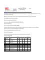
2.11 Page Size Detection
Via the cam moves jointly with the paper guide of the paper cassette, the four tab pieces are driven according to the set position of the paper guide.
Upon installation of the paper cassette, the microswitch detects the condition of the tab pieces and the paper size is recognized.
STATE OF MICROSWITCHES
SW1
SW2
SW3
SW4
Paper size
0
0
0
1
1
1
1
1
1
1
0
1
0
1
1
0
1
0
1
1
1
0
0
0
1
1
1
0
1
1
0
1
Letter
Executive
A4
Legal 14
Legal 13
B5
A5
A6
Copyright 1999, Okidata, Division of OKI America, Inc. All rights reserved.
Service Guide - C7000 Series
Page: 36
Chapter 2 Operation
2.12 Operation at Power-on
2.12.1 Self-diagnostic test
(1) Initial test
The followings are automatically performed at power-on.
(a) ROM check
(b) RAM check
(c) EEPROM check
(d) Flash ROM check
(2) ROM check
ROM is checked by calculating a HASH value.
(3) RAM check
(a) RAMs are by type. Out-of-specification RAM is judged as an error.
(b) The order of mounted RAMs is checked. Out-of-standard order is judged as an error.
(c) Each slot's RAM is checked by read-after-write operation.
(4) EEPROM check
Specific data stored at a fixed address of EEPROM is checked..
(5) Flash ROM check
The flash ROM format is checked. Unformatted ROM is formatted after read-after-write checking.
(6) Option unit check
Before the printer goes into the operation mode, the presence of the option units (e.g., the HDD, NIC, option trays and duplex unit) is checked.
Copyright 1999, Okidata, Division of OKI America, Inc. All rights reserved.
Service Guide - C7000 Series
Page: 37
Chapter 2 Operation
2.13 Color Misalignment Detection
Reflection-type optical sensors for detecting color misalignment (Z71-PCB) are mounted on the belt at the right and left ends, respectively, in front of the toner
scraping (cleaning) blade which is at the back of the belt unit. The color misalignment detection pattern is printed on the belt at each of the right and left ends and,
by reading the patterns by the reflection-type optical sensors, the misalignment amounts are measured with respect to Black to determine correction values.
Then, the misalignment in main-scanning, sub-scanning and slanting directions is corrected. These operations are performed at power-on, at cover-close and
every 200 pages.
Copyright 1999, Okidata, Division of OKI America, Inc. All rights reserved.
Service Guide - C7000 Series
Page: 38
Chapter 2 Operation
2.14 Version Read of Units Replaced Periodically
The version of each of the I/D, fuser unit and belt unit which are replaced periodically is determined whether it is new or previous according to whether the fuse in
it is conducting or out of conduction. When the fuse is conducting, the unit is decided that it is new. The "new" or "previous" judgment is performed at power-on
and at cover-close. The life counter of every new unit is reset and the "new" or "previous" judging purpose fuse in the unit is cut.
Copyright 1999, Okidata, Division of OKI America, Inc. All rights reserved.
Service Guide - C7000 Series
Page: 39
Chapter 2 Operation
2.15 Life Count for Units Replaced Periodically
The life of each of the I/D, fuse unit and belt unit which are replaced periodically is counted as shown in the following table:
Unit Name
Condition
Action
I/D (Image Drum
Cartridge)
The number of drum revolutions is counted, on a letter
paper length
+ continuous-printing paper interval basis. End of Life:
Time when a distance equivalent to pages of 20K is
printed (3P/J). Warning (the unit can still be used).
Warning (the unit can still
be used).
Toner Cartridge
The number of dots printed is counted. The used
amount is determined based on the counter value (See
section 2.16). End of Life: Time when toner low occurs.
Do not use the unit
anymore.
Belt Unit
The number of drum revolutions is counted, on a letter
paper length
+ continuous-printing paper interval basis. The count of
one is performed every time when one page is passed.
End of Life: Time when the counter value reaches 60K.
Warning (the unit can still be used).
Warning (the unit can still
be used).
Fuser Unit
The count of one is performed every time when one
page is passed.
End of Life: Time when the counter value reaches 60K.
Warning (the unit can still
be used).
Copyright 1999, Okidata, Division of OKI America, Inc. All rights reserved.
Service Guide - C7000 Series
Page: 40
Chapter 2 Operation
2.16 Toner Consumption Detection
The used toner amount is detected by counting the number of dots printed. The counting starts after toner low is removed. The sum of the counted values is
stored in EEPROM. Upon detection of toner low, the amount used is forcedly set to 8%. After that, when the equivalent of pages of 1K on A4 and 5% duty is
reached, toner-empty occurs and the printing stops.
Copyright 1999, Okidata, Division of OKI America, Inc. All rights reserved.
Service Guide - C7000 Series
Page: 41
Chapter 3 Disassembly
3.0 Precaution in Replacing Parts
This section describes the procedure for replacing the parts, assemblies and units in the field. The replacing procedure is given for detachment. To attach, use
the reverse procedure.
3.1 Precautions in Replacing Parts
3.2 Parts layout
3.3 Replacing Parts
Copyright 1999, Okidata, Division of OKI America, Inc. All rights reserved.
Service Guide - C7000 Series
Chapter 3 Disassembly
3.1 Precaution in Replacing Parts
(1)
Before starting parts replacement, remove the AC cable and interface cable.
(a) Removing the AC cable
i) Turn off ("o") the power switch of the printer.
ii) Disconnect the AC inlet plug of the AC cable from the AC receptacle.
iii) Disconnect the AC cable and interface cable from the printer.
(b) Reconnecting the AC cable
i) Connect the AC cable and interface cable to the printer.
ii) Connect the AC inlet plug to the AC receptacle.
iii) Turn on ("I") the power switch of the printer.
(2)
Do not disassemble the printer, if operating normally.
(3)
Do not remove unnecessary parts: try to keep disassembly to a minimum.
(4)
Use specified service tools.
(5)
When disassembling, follow the determined sequence. Otherwise, parts may be damaged.
(6)
Since screws, collars and other small parts are likely to be lost, they should temporarily be
Page: 42
(7)
attached to the original positions.
When handling ICs such as microprocessors, ROM and RAM, and circuit boards, follow
standard electrostatic procedures.
(8)
Do not place printed circuit boards directly on the equipment or floor.
No.
1
Service Tools
Tools
Qty
No. 1-100 Philips
screwdriver
No. 2-200 Philips
screwdriver, Magnetized
1
3
No. 3-100 screwdriver
1
4
No. 5-200 screwdriver
1
5
Digital multimeter
1
6
Pliers
1
7
Handy cleaner
1
8
LED Head cleaner
P/N 51802901
1
2
1
Place of Use
2-2.5 mm
screws
3-5 mm screws
Cleans LED
head
Copyright 1999, Okidata, Division of OKI America, Inc. All rights reserved.
Remarks
Service Guide - C7000 Series
Chapter 3 Disassembly
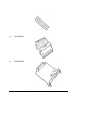
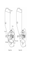
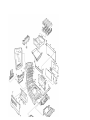
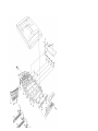
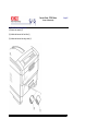
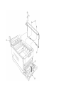
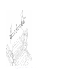
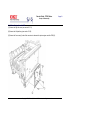
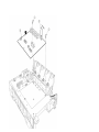
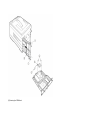
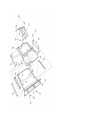
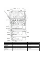
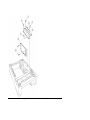
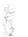
3.2 Parts Layout
Page: 43
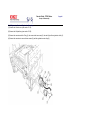
[Top Cover Assy}
[Printer Unit]
[Cassette Guide Assy (L), (R)]
[Duplex Unit]
Copyright 1999, Okidata, Division of OKI America, Inc. All rights reserved.
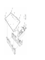
Service Guide - C7000 Series
Chapter 3 Disassembly
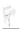
Top Cover Assy
Page: 44
Copyright 1999, Okidata, Division of OKI America, Inc. All rights reserved.
Service Guide - C7000 Series
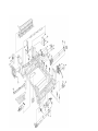
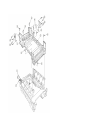
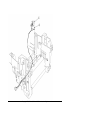
Chapter 3 Disassembly
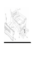
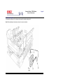
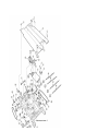
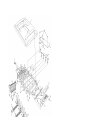
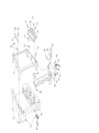
Printer Unit
[Printer Unit 1/2]
Page: 45
Printer Unit 2/2]
Copyright 1999, Okidata, Division of OKI America, Inc. All rights reserved.
Service Guide - C7000 Series
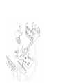
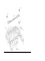
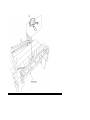
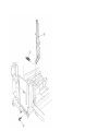
Chapter 3 Disassembly
Cassette Guide Assy (L), (R)
Page: 46
Copyright 1999, Okidata, Division of OKI America, Inc. All rights reserved.
Service Guide - C7000 Series
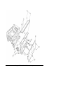
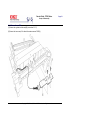
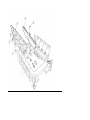
Chapter 3 Disassembly
Duplex Unit
Page: 47
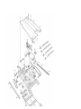
Service Guide - C7000 Series
Page: 48
Chapter 3 Disassembly
3.3 Replacing Parts
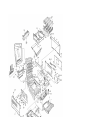
This section described how to replace the parts and assemblies shown in the following disassembling system diagram.
3.3.1 Top Cover
3.3.2 LED assy / LED assy Spring
3.3.3 Top Cover Unit
3.3.4 Control Panel Assy / Control Panel Bezel / LED Control PWB / Toner Sensors / Stacker Full Sensor / Control Panel / Control Panel Tape Harness / Eject
Rollers
3.3.5 Top Cover handle / Top cover Latch / Top Cover Latch Spring
3.3.6 Eject Guide Assy
3.3.7 Cassette Assy / Front Cover Assy / Front Cover Inner Battle
3.3.8 Retard Pad Assy/ Retard Pad Assy Spring
3.3.9 Feed Roller and Nudger Roller
3.3.10 Rear Cover
3.3.11 Face-Up Tray
3.3.12 Left Side Cover
3.3.13 Right Side Cover
3.3.14 Multi-purpose Tray Assy / Multi-purpose Tray Cover Assy / Links / Multi-purpose Tray Top Cover / Multi-purpose Tray Drive gear
3.3.15 Drum Contact Assys
3.3.16 Registration Roller Assy (A) / Registration Drive Gear (A)
3.3.17 Registration Roller Assy (B)
3.3.18 Registration Clutch and Registration Motor Assy
3.3.19 Main Cooling Fan
3.3.20 Color Registration Sensor Assy
3.3.21 Duplex Guide Assy
3.3.22 Electrical Chassis Cooling Fan
3.3.23 Printer Engine Controller PWB
3.3.24 Printer Unit Chassis
3.3.25 Entrance Cassette Sensor Actuator
3.3.26 Entrance Sensor PWB
3.3.27 Entrance MT Sensor Actuator and Entrance Belt Sensor Actuator
3.3.28 Fuser Exit Roller
3.3.29 Exit Sensor Assy
3.3.30 Fuser Latching Handle (L)
3.3.31 Belt Motor Assy
3.3.32 Fuser Latching Handle (R)
3.3.33 Main Motor Assy
3.3.34 Main Feeder Drive Motor
3.3.35 Contact Assy / Left Plate Assy
3.3.36 Low Voltage Power Supply
3.3.37 High Voltage Power Supply
3.3.38 Main Feed Assy
3.3.39 Cassette / Left Guide Assy
3.3.40 Cassette / Right Guide Assy
3.3.41 Fuser Unit
3.3.42 Belt Unit
3.3.43 Duplex Unit
3.3.44 Guide Rails (L) and (R)
3.3.45 Duplex Transport Assembly
3.3.46 CU Assy
Copyright 1999, Okidata, Division of OKI America, Inc. All rights reserved.
Service Guide - C7000 Series
Chapter 3 Disassembly
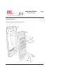
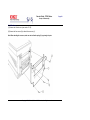
3.3.1 Top Cover
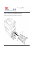
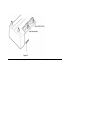
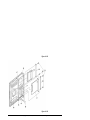
(1) Open the Top Cover assy.
(2) Remove the nine screws (1) to detach the top cover (2).
Copyright 1999, Okidata, Division of OKI America, Inc. All rights reserved.
Page: 49
Service Guide - C7000 Series
Page: 50
Chapter 3 Disassembly
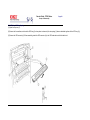
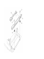
3.3.2 LED Assy / LED Assy Spring
(1) Open the top cover (1).
(2) Remove the three cables, and unhook the LED Assy (2) at two places to demount it (the two springs (3) become detached together with the LED Assy (2)).
(3) Remove the LED connector (4). When assembling, attach the LED connector (4) to the LED head and insert the flat cable into it.
Copyright 1999, Okidata, Division of OKI America, Inc. All rights reserved.
Service Guide - C7000 Series
Page: 51
Chapter 3 Disassembly
3.3.3 Top Cover Unit
(1) Remove the top cover (see section 3.3.1).
(2) Remove the rear cover (see section 3.3.10).
(3) Remove the left side cover (see section 3.3.12).
(4) Remove the right side cover (see section 3.3.13).
(5) Remove the shield plates A and B (see section 3.3.22), and unplug the connector to separate the top cover.
(6) Disengage the top cover unit (1) at two places to detach it.
Copyright 1999, Okidata, Division of OKI America, Inc. All rights reserved.
Service Guide - C7000 Series
Chapter 3 Disassembly
3.3.4 Control Panel Assy / Control Panel Bezel / LED Control PWB / Toner Sensors / Stacker Full Sensor /
Control Panel / Control Panel Tape Harness / Eject Rollers
(1) Detach the control panel bezel placed in the control panel Assy (2).
(2) Remove the screw (1) to demount the control panel Assy (2).
(3) Detach the control panel tape harness (14).
(4) Remove the top cover unit (see section 3.3.3).
(5) Unscrew the four screws (3) to remove the earth plate (4).
(6) Remove the two screws (5), unhook all the connectors (6) and demount the LED control PWB (7).
(7) Remove the screw (8).
(8) Disengage the four claws to demount the toner sensor .
(9) Demount the stacker full sensor (12).
(10) Demount the exit rollers (15).
(11) Detach the LED harnesses, K, Y, M and C (16).
(12) Detach the top cover inner frame Assy (17).
Page: 52
Copyright 1999, Okidata, Division of OKI America, Inc. All rights reserved.
Service Guide - C7000 Series
Page: 53
Chapter 3 Disassembly
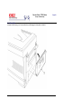
3.3.5 Top Cover Handle / Top Cover Latch / Top Cover Latch Spring
(1) Remove the two screws (1) to detach the top cover handle (2) and disengage the top cover latch (3) (at the same time, the two top cover latch springs (4)
become detached).
Copyright 1999, Okidata, Division of OKI America, Inc. All rights reserved.
Service Guide - C7000 Series
Chapter 3 Disassembly
3.3.6 Eject Guide Assy
(1) Remove the five screws (1) to detach the eject guide assy (2).
Page: 54
Copyright 1999, Okidata, Division of OKI America, Inc. All rights reserved.
Service Guide - C7000 Series
Chapter 3 Disassembly
3.3.7 Cassette Assy / Front Cover Assy / Front Cover Inner Baffle
(1) Detach the cassette assy (1).
(2) Open the front cover (2), and disengage it at two places to detach it.
(3) Detach the front cover inner baffle (3).
Page: 55
Copyright 1999, Okidata, Division of OKI America, Inc. All rights reserved.
Service Guide - C7000 Series
Chapter 3 Disassembly
3.3.8 Retard Pad Assy / Retard Pad Assy Spring
(1) Remove the cassette (1).
(2) Detach the retard pad assy (2) (at the same time, the spring (3) becomes detached).
Page: 56
Copyright 1999, Okidata, Division of OKI America, Inc. All rights reserved.
Service Guide - C7000 Series
Chapter 3 Disassembly
3.3.9 Feed Roller and Nudger Roller
(1) Remove the cassette (1).
(2) Unlatch and demount the feed roller (1).
(3) Unlatch and demount the nudger roller (2).
Page: 57
Copyright 1999, Okidata, Division of OKI America, Inc. All rights reserved.
Service Guide - C7000 Series
Chapter 3 Disassembly
3.3.10 Rear Cover
(1) Remove the left side cover (see section 3.3.12).
(2) Remove the four screws (2) to detach the rear cover (1).
Note: When attaching the rear cover, take care not to allow the spring (3) to get caught in parts.
Copyright 1999, Okidata, Division of OKI America, Inc. All rights reserved.
Page: 58
Service Guide - C7000 Series
Chapter 3 Disassembly
3.3.11 Face-Up Tray
(1) Open the face-up tray (1) in the arrow direction, and disengage it at two places to detach it.
Page: 59
Copyright 1999, Okidata, Division of OKI America, Inc. All rights reserved.
Service Guide - C7000 Series
Chapter 3 Disassembly
3.3.12 Left Side Cover
(1) Open the top cover (1).
(2) Open the front cover (2) and undo the screw (3).
(3) Remove the four screws (4) to detach the left side cover (5).
Page: 60
Copyright 1999, Okidata, Division of OKI America, Inc. All rights reserved.
Service Guide - C7000 Series
Chapter 3 Disassembly
3.3.13 Right Side Cover
(1) Open the top cover (1).
(2) Open the front cover (2) and undo the screw (3).
(3) Remove the four screws (4) to detach the right side cover (5).
Page: 61
Copyright 1999, Okidata, Division of OKI America, Inc. All rights reserved.
Service Guide - C7000 Series
Page: 62
Chapter 3 Disassembly
3.3.14 Multi-purpose Tray Assy / Links
Multipurpose Tray Assy / Multipurpose Tray Cover Assy / Links / Multipurpose Tray Top Cover / Multipurpose Tray Drive Gear
(1) Remove the left side cover (see section 3.3.12).
(2) Remove the right side cover (see section 3.3.13).
(3) Remove the left plate Assy (see section 3.3.22).
(4) Remove the three screws (1) to detach the multipurpose tray top cover (2).
(5) Remove the three screws (3) (two of them are black) and the connector to detach the multipurpose tray (4).
(6) Disengage A and B at both sides of the assembly to detach the multipurpose tray cover Assy (5) (at the same time, the links (7) become detached).
(7) Unhook and detach the multipurpose tray drive gear (8).
Copyright 1999, Okidata, Division of OKI America, Inc. All rights reserved.
Service Guide - C7000 Series
Page: 63
Chapter 3 Disassembly
3.3.15 Drum Contact Assys
(1) Insert a flatblade screwdriver between the printer case and the drum contact assy (1) to demount the drum contact assy (1).
Copyright 1999, Okidata, Division of OKI America, Inc. All rights reserved.
Service Guide - C7000 Series
Chapter 3 Disassembly
3.3.16 Registration Roller Assy (A) / Registration Drive Gear (A)
(1) Remove the left side cover (see section 3.3.12).
(2) Remove the right side cover (see section 3.3.13).
(3) Remove the multipurpose tray (see section 3.3.14).
(4) Remove the four screws (1) to demount the registration roller Assy (A) (2).
(5) Remove the E ring (3) to detach the registration gear (A) (4).
Page: 64
Copyright 1999, Okidata, Division of OKI America, Inc. All rights reserved.
Service Guide - C7000 Series
Chapter 3 Disassembly
3.3.17 Registration Roller Assy (B)
(1) Remove the cassette Assy.
(2) Open the front cover.
(3) Remove the right side cover (see section 3.3.13).
(4) Remove the left plate Assy (see section 3.3.22).
(5) Remove the registration clutch (see section 3.3.18).
(6) Unscrew the four screws (1), and pull out the registration Assy (B) (1) in the arrow direction.
Page: 65
Copyright 1999, Okidata, Division of OKI America, Inc. All rights reserved.
Service Guide - C7000 Series
Page: 66
Chapter 3 Disassembly
3.3.18 Registration Clutch and Registration Motor Assy
(1) Remove the left side cover (see section 3.3.12).
(2) Remove the left plate Assy (see section 3.3.22).
(3) Remove the connector and the E ring (1), then remove the two screws (3), the earth (4) and the registration clutch (2).
(4) Remove the connector to remove the two screws (5) and the registration motor Assy (6).
Copyright 1999, Okidata, Division of OKI America, Inc. All rights reserved.
Service Guide - C7000 Series
Chapter 3 Disassembly
3.3.19 Main Cooling Fan
(1) Unhook the connector (1), and remove the screw (2) and the cooling fan (3).
Note: When attaching the cooling fan, observe its correct orientation.
Page: 67
Copyright 1999, Okidata, Division of OKI America, Inc. All rights reserved.
Service Guide - C7000 Series
Chapter 3 Disassembly
3.3.20 Color Registration Sensor Assy
(1) Remove the two screws (1) and the two connectors to demount the color registration sensor assy (2).
(2) Remove the earth plate B (3).
Page: 68
Copyright 1999, Okidata, Division of OKI America, Inc. All rights reserved.
Service Guide - C7000 Series
Chapter 3 Disassembly
3.3.21 Duplex Guide Assy
(1) Unlatch and demount the duplex guide (1).
Page: 69
Copyright 1999, Okidata, Division of OKI America, Inc. All rights reserved.
Service Guide - C7000 Series
Chapter 3 Disassembly
3.3.22 Electrical Chassis Cooling Fan
(1) Unscrew the screws (1) to remove the plate A (2).
(2) Unscrew the screws (3) to remove the shield plate B (4).
(3) Remove the printer engine controller PWB (see section 3.3.30).
(4) Unscrew the screws (5) to remove the shield plate (6).
(5) Unscrew the screws (7) to demount the electrical chassis cooling fan (8).
Page: 70
Copyright 1999, Okidata, Division of OKI America, Inc. All rights reserved.
Service Guide - C7000 Series
Chapter 3 Disassembly
3.3.23 Printer Engine Controller PWB
(1) Remove the right side cover (see section 3.3.13).
(2) Remove the left plate Assy (see section 3.3.22).
(3) Remove the five screws (1) and all the connectors to demount the printer engine controller PWB (2).
Copyright 1999, Okidata, Division of OKI America, Inc. All rights reserved.
Page: 71
Service Guide - C7000 Series
Chapter 3 Disassembly
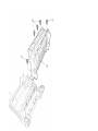
3.3.24 Printer Unit Chassis
(1) Unscrew the two screws (1) and remove the AC inlet (2).
(2) Unscrew the four black screws (3) and five screws (4) to detach the printer unit chassis (5).
(3) Unscrew the four black screws (6) and remove the left top cover spring Assy (7).
(4) Unscrew the four black screws (8) and remove the right top cover spring Assy (9).
Page: 72
Copyright 1999, Okidata, Division of OKI America, Inc. All rights reserved.
Service Guide - C7000 Series
Chapter 3 Disassembly
3.3.25 Entrance Cassette Sensor Actuator
(1) Remove the printer unit chassis (see section 3.3.24).
(2) Turn over the main chassis.
(3) Remove the two clamps with needlenose pliers to detach the entrance cassette sensor actuator (1).
Page: 73
Copyright 1999, Okidata, Division of OKI America, Inc. All rights reserved.
Service Guide - C7000 Series
Chapter 3 Disassembly
3.3.26 Entrance Sensor PWB
(1) Remove the registration roller assb (B) (see section 3.3.17).
(2) Remove the two screws (10 to detach the entrance sensor PWB (2).
Copyright 1999, Okidata, Division of OKI America, Inc. All rights reserved.
Page: 74
Service Guide - C7000 Series
Chapter 3 Disassembly
3.3.27 Entrance MT Sensor Actuator and Entrance Belt Sensor Actuator
(1) Remove the entrance sensor PWB (R71) (see section 3.3.26).
(2) Unlatch and detach the entrance MT sensor actuator (1).
(3) Unlatch and detach the entrance belt actuator (2).
Page: 75
Copyright 1999, Okidata, Division of OKI America, Inc. All rights reserved.
Service Guide - C7000 Series
Chapter 3 Disassembly
3.3.28 Fuser Exit Roller
(1) Unscrew the two screws (1) to remove the duplex gate solenoid Assy (2).
(2) Unscrew the screw (3) to remove the fuser exit roller contact (4).
(3) Remove the fuser drive gear -A (5) and fuser drive gear -A (6).
(4) Unscrew the screw (7) to remove the fuser drive gear -C (8).
(5) Unlatch and detach the fuser drive gear -B (9) and fuser exit roller bush (R) (10).
(6) Unlatch and detach the fuser exit roller bush (L) (11) and fuser exit roller (12).
Page: 76
Copyright 1999, Okidata, Division of OKI America, Inc. All rights reserved.
Service Guide - C7000 Series
Chapter 3 Disassembly
3.3.29 Exit Sensor Assy
(1) Remove the fuser exit roller (see section 3.3.28).
(2) Remove the screw (1) and connector to detach the (red and blue) exit sensor assy (2).
Page: 77
Copyright 1999, Okidata, Division of OKI America, Inc. All rights reserved.
Service Guide - C7000 Series
Chapter 3 Disassembly
3.3.30 Fuser Latching Handle (L)
(1) Remove the latching handle spring (1).
(2) Unscrew the screw (2) to detach the fuser latching handle (L) (3).
Page: 78
Copyright 1999, Okidata, Division of OKI America, Inc. All rights reserved.
Service Guide - C7000 Series
Chapter 3 Disassembly
3.3.31 Belt Motor Assy
(1) Remove the fuser latching handle (R) (see section 3.3.32).
(2) Remove the two screws (1) to detach the two connectors (2).
(3) Detach the belt motor Assy (3).
Page: 79
Copyright 1999, Okidata, Division of OKI America, Inc. All rights reserved.
Service Guide - C7000 Series
Chapter 3 Disassembly
3.3.32 Fuser Latching Handle (R)
(1) Remove the printer unit chassis (see section 3.3.24).
(2) Remove the E ring (1).
(3) Remove the fuser latching handle spring (2) to detach the fuser latching handle (R) (3).
Page: 80
Copyright 1999, Okidata, Division of OKI America, Inc. All rights reserved.
Service Guide - C7000 Series
Chapter 3 Disassembly
3.3.33 Main Motor Assy
(1) Remove the belt motor assy (see section 3.3.31).
(2) Remove all the connectors.
(3) Remove the four screws (1) to detach the main motor assy (2).
Page: 81
Copyright 1999, Okidata, Division of OKI America, Inc. All rights reserved.
Service Guide - C7000 Series
Chapter 3 Disassembly
3.3.34 Main Feeder Drive Motor
(1) Remove the two screws (1) to detach the main feeder drive motor (2).
(2) Unscrew the screw (3) to remove the main feeder drive motor bracket (4).
(3) Remove the main feeder drive motor gears A (5) and B (6).
Page: 82
Copyright 1999, Okidata, Division of OKI America, Inc. All rights reserved.
Service Guide - C7000 Series
Chapter 3 Disassembly
3.3.35 Contact Assy / Left Plate Assy
(1) Remove the printer unit chassis (see section 3.3.24).
(2) Remove the four screws (1) to detach the left plate Assy (2).
(3) Remove the screw (3) to detach the contact Assy (4).
Page: 83
Copyright 1999, Okidata, Division of OKI America, Inc. All rights reserved.
Service Guide - C7000 Series
Chapter 3 Disassembly
3.3.36 Low Voltage Power Supply
(1) Remove the printer unit chassis (see section 3.3.24).
(2) Unhook the connector (1).
(3) Unscrew the screw (2) to remove the earth cable (3).
(4) Unscrew the six screws (4) to detach the low voltage power supply (5).
Page: 84
Copyright 1999, Okidata, Division of OKI America, Inc. All rights reserved.
Service Guide - C7000 Series
Chapter 3 Disassembly
3.3.37 High Voltage Power Supply
(1) Remove the contact Assy (see section 3.3.35).
(2) Unhook the connector of the high voltage power supply (2).
(3) Remove the two screws (1) to detach the high voltage power supply (2) and the tape harness (3).
Page: 85
Copyright 1999, Okidata, Division of OKI America, Inc. All rights reserved.
Service Guide - C7000 Series
Chapter 3 Disassembly
3.3.38 Main Feed Assy
(1) Remove the printer unit chassis (see section 3.3.24).
(2) Remove the low voltage power supply and high voltage power supply (see sections 3.3.36 and 3.3.37).
(3) Unscrew the five screws (1) to remove the lower plate (2).
(4) Unscrew the four screws (3) to detach the main feed Assy (4).
(5) Unhook and remove the main feed drive gear (5).
Page: 86
Copyright 1999, Okidata, Division of OKI America, Inc. All rights reserved.
Service Guide - C7000 Series
Page: 87
Chapter 3 Disassembly
3.3.39 Cassette / Left Guide Assy
(1) Remove the printer unit chassis (see section 3.3.24).
(2) Remove the main feed Assy (see section 3.3.38).
(3) Remove the three screws (1) to detach the left cassette guide Assy (2). At the same time, the earth plate 3 becomes detached.
(4) Remove the cassette lift spring (4), then remove the plastic slide (5), the cassette lift arm (L) (6) and the plastic roller (7).
(5) Remove the two feet (8).
(6) Remove the cassette lock spring (9), then remove the cassette lock (10).
Copyright 1999, Okidata, Division of OKI America, Inc. All rights reserved.
Service Guide - C7000 Series
Page: 88
Chapter 3 Disassembly
3.3.40 Cassette / Right Guide Assy
(1) Remove the printer unit chassis (see section 3.3.24).
(2) Remove the main feed Assy (see section 3.3.38).
(3) Remove the five screws (1) to detach the right cassette guide Assy (2). At the same time, the earth plate (3) becomes detached.
(4) Remove the cassette lift spring (4), then detach the plastic slide (5), the cassette lift arm (L) (6) and the plastic roller (7).
(5) Unscrew the screw (8) to remove the paper size actuator (9).
(6) Unscrew the screw (10) to remove the paper size sensing PWB (11) in the downward direction.
(7) Remove the two feet (12).
(8) Remove the cassette lock spring (13), then remove the cassette lock (14).
(9) Unscrew the two screws (15) to remove the 2nd tray connector (16).
(10) Unscrew the screw (17), then remove the duplex Assy ground contact (18).
Copyright 1999, Okidata, Division of OKI America, Inc. All rights reserved.
Service Guide - C7000 Series
Chapter 3 Disassembly
3.3.41 Fuser Unit
(1) Open the top cover (1).
(2) Push the right and left fuser levers (blue) (2) in the arrow direction to detach the fuser unit (3).
Copyright 1999, Okidata, Division of OKI America, Inc. All rights reserved.
Page: 89
Service Guide - C7000 Series
Chapter 3 Disassembly
3.3.42 Belt Unit
(1) Open the top cover (1).
(2) Remove the I/D unit.
(3) Push the lever (blue) (2) in the arrow direction, raise the handle (blue) and detach the belt unit (3).
Page: 90
Copyright 1999, Okidata, Division of OKI America, Inc. All rights reserved.
Service Guide - C7000 Series
Chapter 3 Disassembly
3.3.43 Duplex Unit
(1) Remove the cassette Assy, the front cover Assy and the front cover inner baffle.
(2) Unlatch the rear at the right and left, and pull the duplex unit 1 toward the front.
Copyright 1999, Okidata, Division of OKI America, Inc. All rights reserved.
Page: 91
Service Guide - C7000 Series
Chapter 3 Disassembly
3.3.44 Guide Rails (L) and (R)
(1) Remove the duplex unit (see section 3.3.43).
(2) Remove the six screws 1 to detach the guide rails (L) 2 and (R) 3.
Copyright 1999, Okidata, Division of OKI America, Inc. All rights reserved.
Page: 92
Service Guide - C7000 Series
Page: 93
Chapter 3 Disassembly
3.3.45 Duplex Transport Assembly
(1) Turn over the duplex transport Assy.
(2) Unscrew the three screws (1) and five screws (2) to detach the plate (3).
(3) Unplug the connector and detach the mold Assy (4).
(4) Detach the two actuators (5).
(5) Unscrew the screws (6) and (7) to remove the earth (8).
(6) Unhook the connector and disengage the two claws to detach PCB-MOP (9).
(7) Unplug the cable and, warping the claw, detach the transport sensor.
(8) Unscrew the two screws to detach the cord duplex connector Assy.
(9) Unscrew the screw (10) to remove the earth (11).
(10) Unscrew the screw to remove the earth (13).
(11) Unscrew the screw (14) to remove the earth (15).
(12) Detach the bush (16), gear (17) and bush (18), then detach the roller (19).
(13) Unscrew the screw (20) to remove the earth (21).
(14) Detach the gear (22) and bush (23). At the same time, the mini pitch belt (24) becomes detached.
(15) Detach the gear (25) and bush (26), then detach the roller (27). At the same time, the mini pitch belt (27) becomes detached.
(16) Unscrew the screw (29) to remove the earth (30).
(17) Remove the E ring (31) and three screws (32) to detach the motor Assy (33). At the same time, the earth (34) becomes detached.
(18) Detach the gear (35) and bush (36).
(19) Detach the gear (37), knock-pin (38) and bush (39), then detach the roller (40).
(20) Detach the bush (41), gear (42), knock-pin (43) and bush (44), then detach the roller (45). At the same time, the earth's (46) and (47) become detached.
(21) Detach the idle roller shaft and the idle roller, then detach the idle roller springs (eight springs).
(22) Remove the cable of the duplex transport sensor Assy from the claw of the cover-upper. Disengage the claw, then detach the sensor.
Copyright 1999, Okidata, Division of OKI America, Inc. All rights reserved.
Service Guide - C7000 Series
Chapter 3 Disassembly
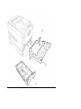
3.3.46 CU Assy
(1) Pulling out Controller Board
1. Undo the two screws 1.
2. Pull the controller board 2 out.
3. Place the controller board 2 on a flat table.
(2) Detaching Fan
1. Remove the connector 3.
2. Remove the two screws 4.
3. Detach the fan 5.
Page: 94
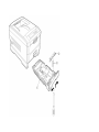
(3) Removing the CRM Board
1. Unscrew the four screws (6) to remove the fan bracket (7).
2. Unscrew the four screws (8) to remove the plate support (9) and the guide rail A (10).
3. Unscrew the two screws (11) to remove the guide rail (11) .
4. Unscrew the two screws (12) and three screws (14), then detach the CRM board (15).
Copyright 1999, Okidata, Division of OKI America, Inc. All rights reserved.
Service Guide - C7000 Series
Page: 95
Chapter 4 Adjustments
4.0 Adjustments
Adjustments on the C7000 Series of printers are made by key entry on the operator panel. In addition to a standard menu, there is a maintenance menu in each
printer. Select the one that serves the purpose of intended adjustment.
Copyright 1999, Okidata, Division of OKI America, Inc. All rights reserved.
Service Guide - C7000 Series
Chapter 4 Adjustments
4.1 Maintenance Modes and Their Functions
4.1.1 Maintenance Menu
4.1.2 Engine Maintenance Menu
4.1.3 CRM Board Adjustments
Copyright 1999, Okidata, Division of OKI America, Inc. All rights reserved.
Page: 96
Service Guide - C7000 Series
Page: 97
Chapter 4 Adjustments
4.1.1 Maintenance Menu
The following menu category includes the maintenance menu category. The following can be set from this menu.
Category
Item (1st Line)
Maintenance
Menu
Value (2nd
Line)
DF
Functions
Power Save Mode Enabled
Disabled
*
Normal Paper
Back Setting
0
+1
+2
-2
-1
*
Normal Paper
Color Setting
0
+1
+2
-2
-1
*
Transparency
Black Setting
0
+1
+2
-2
-1
*
Transparency
Color Setting
0
+1
+2
-2
-1
*
Sets the Power Save Mode
enabled/disabled. The shift time to enable
the Power Save mode can be changed
according to the POWER SAVE SHIFT TIME
item of SYSTEM CONFIG. MENU.
Implements fine adjustment of BLACK
printing on normal paper when unclear
characters or spots are often found on print
results. With dispersed or snowed printing
in the part at high-density, decrease the
value. With unclear printing, increase the
value.
Implements fine adjustment of COLOR
printing on normal paper when unclear
characters or spots are often found on the
print result. With dispersed or snowed
printing in the part at high-density, decrease
the value. With unclear printing, increase the
value.
Implements fine adjustment of BLACK
printing on Transparency when unclear
characters or spots are often found on the
print result. With dispersed or snowed
printing in the part at high-density, decrease
the value. With unclear printing, increase the
value.
Implements fine adjustment of COLOR
printing on Transparency when unclear
characters or spots are often found on the
print result. With dispersed or snowed
printing in the part at high-density, decrease
the value. With unclear printing, increase the
value.
Copyright 1999, Okidata, Division of OKI America, Inc. All rights reserved.
Service Guide - C7000 Series
Page: 98
Chapter 4 Adjustments
4.1.2 Engine maintenance mode
The engine maintenance mode includes three modes, levels 1 to 3. The level 1 aims to assist in checking the media transport systems and the basic operations
of printing systems etc. The level 2, which sets the consumable counter and tests the color registration adjustment function, does not require relatively special
knowledge. Working with the level 3, including process parameter setting, takes expertise and the level contains PU individual experimental elements. Basically
do not use items other than those in the level 1.
4.1.2.1 Operator Panel
4.1.2.2 General self-diagnosis mode (level 1)
4.1.2.3 Switch scan test
4.1.2.4 Motor and clutch test
4.1.2.5 Test Printing
4.1.2.6 NVM initialization
4.1.2.7 Consumable counter display
4.1.2.8 Consumable counter display - continuous
4.1.2.9 Error Messages and their Details
Copyright 1999, Okidata, Division of OKI America, Inc. All rights reserved.
Service Guide - C7000 Series
Chapter 4 Adjustments
4.1.2.1 Operator panel
Operational descriptions about the self-diagnosis are premised on the following operator panel layout.
Copyright 1999, Okidata, Division of OKI America, Inc. All rights reserved.
Page: 99
Service Guide - C7000 Series
Chapter 4 Adjustments
4.1.2.2 General self-diagnosis mode (level 1)
Following is the menu of the general self-diagnosis mode.
l
Switch Scan Test
l
LED Head Test
l
Motor and Clutch Tests
l
Test Pattern Execution
l
NVM Initialization
l
Consumable Counter Display
l
Consumable Counter Display - Continuous
4.1.2.2.1 Entering self-diagnosis mode (level 1)
4.1.2.2.2 Exiting self-diagnosis mode
Copyright 1999, Okidata, Division of OKI America, Inc. All rights reserved.
Page: 100
Service Guide - C7000 Series
Page: 101
Chapter 4 Adjustments
4.1.2.2.1 Entering self-diagnosis mode (level 1)
1. Detach the main controller board.
2. While holding the 1 11 11 and 4 44 44 keys down at the same time, turn the power on to enter this mode.
3. "ENGINE DIAG MODE XX.XX" appears in the upper display. XX.XX shows the version of ROM.
4. Go to each self-diagnosis step by using the 1 11 11 and 5 55 55 keys (pressing 1 11 11 and 5 55 55 keys rotates the
menu items).
Copyright 1999, Okidata, Division of OKI America, Inc. All rights reserved.
Service Guide - C7000 Series
Page: 102
Chapter 4 Adjustments
4.1.2.2.2 Exiting self-diagnosis mode
1. While "ENGINE DIAG MODE XX.XX" is displayed, press the (0) key, or turn the power off and, after ten seconds, on again.
Copyright 1999, Okidata, Division of OKI America, Inc. All rights reserved.
Service Guide - C7000 Series
Page: 103
Chapter 4 Adjustments
4.1.2.3 Switch scan test
This self-diagnosis is used when the input sensor and the switch are checked.
1. Enter the general diagnosis mode, and press and hold the (1) and (5) keys down until "SWITCH SCAN" appears on the upper display (the (1) key increments a
test item and the (5) key decrements a test item).
2. Table 4-1 lists SCAN numbers. Hold the (2) and (6) keys down until the SCAN number for a unit to be tested shows up on the upper display (the (2) key
increments a test item and the (6) key decrements a test item).
3. In response to the press of the (3) key, the test starts, the SWITCH SCAN number begins blinking, then the corresponding unit number (any of 1 to 4) and the
current status are displayed.
Operate the units (Figure 4-1). Their respective liquid crystal displays are provided (Displays vary by sensor. See Table 4-1 for details).
4. When the (7) key is touched, the SWITCH SCAN number goes back to an indication view (stops blinking).
5. Repeat steps 2 through 4 as required.
6. To end the test, press the (4) key (the display is restored to the view of step 1).
Copyright 1999, Okidata, Division of OKI America, Inc. All rights reserved.
Service Guide - C7000 Series
Page: 104
Chapter 4 Adjustments
4.1.2.4 Motor and clutch test
This self-check routine is used for testing the motor and clutch.
1. Go to the self-diagnosis (level 1) mode, and hold the (1) and (5) keys down until the upper display of "MOTOR & CLUTCH TEST" is brought up (the (1) key
increments a test item and the (6) key decrements a test item).
2. Hold the (2) and (6) keys down and wait for the display for a unit to be tested to appear on the lower line (the (2) key increments a test item and the (6) key
decrements a test item). Corresponding displays are listed in Table 4-2.
3. Pressing the (3) key starts the test, the unit name blinks, then the corresponding unit is driven for 10 seconds (refer to Figure 4-3).
Note! The view of step 2 is restored after 10-second driving and, with the press of the corresponding switch again, the unit is driven again.
l
Driving corresponding units subject to the constraints listed in Table 4-2. The driving and activating out of the constraints are disabled and the
constraints appear on the lower display.
l
The clutch solenoids must repeat on-off operations in normal printing driving (units that cannot be driven singly from a viewpoint of their mechanical
structures must be driven in combination with the motor).
4. Use the (7) key to stop the drive of the unit (the corresponding unit display remains the same).
5. Repeat the cycle of steps 2 though 4 as the case may be.
6. Pressing the (4) key ends the tests (the display is restored to step 1).
Unit Name Display
Driving Constraints
Constraints Display
BLACK-ID MOTOR
YELLOW-ID MOTOR
MAGENTA-ID
MOTOR
CYAN-ID MOTOR
BELT MTOR
FUSER MOTOR
Remove all the IDs (B, Y, M and C) to drive the unit.
Remove all the IDs (B, Y, M and C) to drive the unit.
REMOVE ID
REMOVE ID
Remove all the IDs (B, Y, M and C) to drive the unit.
Remove all the IDs (B, Y, M and C) to drive the unit.
Remove all the IDs (B, Y, M and C) to drive the unit.
-
REMOVE ID
REMOVE ID
REMOVE ID
-
REGISTRATION MOTOR
MAIN FEEDER MOTOR
REGISTRATION CLUTCH
SENSOR SHUTTER
EXIT SOLENOID
DUP MOTOR (OPTION)
DUP REAR CLUTCH (OPTION)
CASSETTE 2 MOTOR
(OPTION)
CASSETTE2 FEED ROLLER
(OPTION)
CASSETTE3 FEEDER MOTOR
(OPTION)
CASSETTE3 ROLLER CLUTCH
(OPTION)
ID UP/DOWN
FAN1 TEST (POWER UNIT
FAN)
FAN2 TEST (CONTROL BLOCK
FAN)
Remove the cassette 1 to drive the unit.
Remove the cassette 2 to drive the unit.
Remove the cassette 3 to drive the unit.
EXIT TRAY1 CASSETTE
EXIT TRAY2 CASSETTE
EXIT TRAY3 CASSETTE
-
-
-
-
-
-
Copyright 1999, Okidata, Division of OKI America, Inc. All rights reserved.
Service Guide - C7000 Series
Page: 105
Chapter 4 Adjustments
4.1.2.5 Test printing
This self-diagnostic routine is used when the internal test patterns of the PU are printed. Other test patterns are stored in the controller.
1. Go to the self-diagnosis (level 1) mode, and hold the (1) and (5) keys down until "TEST PRINT" comes into view in the upper display (the (1) key is for test item
increment and the (5) key for test item decrement).
2. On the lower display, setting items applicable only to the test printing appear. Hold the (2) and (6) keys down until a target item is displayed (the (2) key is for
item increment and the (6) key for item decrement). When the setting for the item is not required (left at its default), go to step 5.
3. With the press of the (3), (7), the setting item and its setting are displayed on the upper and lower parts, respectively.
Pressing the (3) key increments a setting. Pressing the (7) key decrements a setting. (The last displayed setting is applied.) Repeat step 3 as necessary.
Display
PRINT EXECUTE
TEST PATTERN (TBD)
CASSET
COLOR
FUSER
DUPLEX
Setting
Function
1
2
3
TRAY1
TRAY2
TRAY3
FF
NONE
ON
OFF
ON
OFF
ON
OFF
Starts printing at the press of + key / Ends printing at the press of - key
Selects one of printing patterns:
1: LED Head Drive Pattern
2: Color Registration Adjust Pattern
3: Reserved
Selects a paper-loading end.
Note: When the loading end is set to NONE, only the heater and drivable motors operate
without the IDs and belt being driven.
Selects between color-monochrome printings.
Selects between hater-on and off.
Selects between duplex-on and -off. Prints on both sides of one sheet of paper and then on
the second sheet when ON is selected.
l
A value in the shaded section is initial. The set values are applicable only to this test mode (No writing into EEPROM is performed.)
l
When the (3) key is pressed, with "PRINT EXECUTE" on the lower display after step 2, the test printing is executed using the values designated in steps
2 and 3. Pressing the (7) key suspends the test printing.
l
The following messages are showing at warm-up and during printing.
P: Number of Sheets Printed for Test (in prints)
U: Upper-Heater Temperature Measurement [Set Value] (in units of °C)
L: Lower-Heater Temperature Measurement [Set Value] (in units of °C)
T: Environmental Temperature Measurement (in units of °C)
H: Environmental Humidity Measurement (in units of %)
l
The display is changed at the press of the 3 33 33 key.
YTR, MTR, CTR and KTR mean the transfer voltage settings for colors (in KV).
l
The display is changed at the press of the 3 33 33 key.
YR, MR, CR and KR are the transfer voltage measurements for transfer roller colors (in KV).
4. While "PRINT EXECUTE" is indicated in the lower display after the Item 2 procedure, press Key (3) to start test printing with the values set in Item 2 and 3
procedures.
To suspend test printing, press Key 7 77 77.
At the start of or during test printing, if any alarm listed under the Detail column in the table specified below is found, the corresponding alarm message appears
on the operator panel and test printing is suspended. (For error details, see Sec. 4.1.2.9 Error Messages and their Details.)
Print Patterns:
Patterns 0, 8 ~15: Blank paper output
5. Steps 2 through 4 to be repeated on an as needed basis.
6. Touch the (4) key to end the test (the display is restored to step 1).
Copyright 1999, Okidata, Division of OKI America, Inc. All rights reserved.
Service Guide - C7000 Series
Page: 106
Chapter 4 Adjustments
4.1.2.6 NVM initialization
The self-diagnosis is used to initialize non-volatile memory.
1. Enter the self-diagnosis (Level 1) mode, and continue to press the (1) and (5) keys until "NV-RAM INITIAL" appears on the upper display (the (1) key is for test
item increment and the (5) key for test item decrement).
2. The table No. to be initialized appears. There are two tables to be initialized. Hold the (2) and (6) keys down until a target table No. shows up (the (2) key is for
table No. increment and the (6) key for table No. decrement).
3. The upper "NV-RAM INITIAL" starts blinking upon pressing the (3) key, and all the items in Table 4-3 are initialized by holding the key down for 10 seconds.
4. Press the (4) key to end the test (the display of step 1 is restored).
Initialization Item
Drum Counter
Detail
Black
Yellow
Magenta
Cyan
Belt Unit Counter
Fuser Unit Counter
Toner Counter
Black
Yellow
Magenta
Cyan
Initialization Item
Registration Set.
Initial Value
0
-
Initializes the internal counter after the
replacement of the belt unit.
Initializes the internal counter after the
replacement of the fuser unit.
Initializes the internal counter after the
recovery from each toner low error.
0
-
0
-
0
-
Detail
Yellow LED
Unit
Initializes the internal counter after the
replacement of each drum.
Initializes the X-axis correction value for
Initial Value
0
Unit
1/1200
Point x-axis
Magenta LED
Cyan LED
Registration Set.
Yellow LED
Point
Magenta LED
y-axis (Left)
Cyan LED
Registration Set
Yellow LED
Point y-axis (Right) Magenta LED
Cyan LED
Engine Parameter
the LED head (Yellow/Magenta/Cyan).
Initializes the Y-axis left-correction value
for the LED head
(Yellow/Magenta/Cyan).
Initializes the Y-axis right-correction
value for the LED head
(Yellow/Magenta/Cyan).
Initializes all the items that have been
set using levels 2 and 3.
inch
0
1/1200
inch
0
1/1200
inch
Copyright 1999, Okidata, Division of OKI America, Inc. All rights reserved.
Service Guide - C7000 Series
Page: 107
Chapter 4 Adjustments
4.1.2.7 Consumable Counter Display
The self-diagnosis is used to indicate the consumable consumption status.
1. After entering the general self-diagnosis mode, hold the (1) and (5) keys down until "CONSUMABLE STATUS" appears on the upper display (the (1) key is for
test item increment and the (5) key for test item decrement).
2. By pressing the (2) and (6) keys, the consumption status of the consumables comes into view item by item (the press of the (3) and (7) keys is invalid).
3. Pressing the (4) key ends the test (the display of step 1 is restored).
Item
Upper Display
Lower Display
Format
Unit
Detail
Fuser Unit
FUSER UNIT
******** IMAGES
DEC
Image
Belt Unit
TR BELT UNIT
******** IMAGES
DEC
Image
Black ID Unit
BLACK ID UNIT
******** IMAGES
DEC
Image
Yellow ID Unit
YELLOW ID UNIT
******** IMAGES
DEC
Image
Shows the number of
sheets fed after the
installation of a new
fuser unit to date.
Shows the number of
sheets fed after the
installation of a new
belt unit to date.
Converts the number
of revolutions of each
color's ID unit after the
installation of that unit
to date into a count in
letter (A4) size paper
sheets and shows it.
Shows the remaining
amount of each color's
toner.
Magenta ID Unit
MAGENTA ID
UNIT
CYAN ID UNIT
BLACK TONER
YELLOW TONER
MAGENTA TONER
CYAN TONER
******** IMAGES
DEC
Image
******** IMAGES
***%
***%
***%
***%
DEC
DEC
DEC
DEC
DEC
Image
%
%
%
%
Cyan ID Unit
Black Toner
Yellow Toner
Magenta Toner
Cyan Toner
Copyright 1999, Okidata, Division of OKI America, Inc. All rights reserved.
Service Guide - C7000 Series
Page: 108
Chapter 4 Adjustments
4.1.2.8 Consumable Counter Display - Continuos
The self-diagnosis is used to indicate the consumable life-cycle consumption status.
The consumable life-cycle consumption status, a count not initialized even after the replacement
of a consumable, is counted without break.
1. Enter the general self-diagnosis mode, and the (1) and (5) keys down until the upper display "PRINTER STATUS" appears (the (1) key is for item increment
and the (5) key for item decrement).
2. When the (2) and (6) keys are pressed, the life-cycle consumption status of the consumables shows up item by item (the press of the (3) and (7) keys is
invalid).
3. Pressing the (4) key ends the test (flips back to the display of 1).
Item
Upper Display
Lower Display
Format
Unit
Detail
Total Number of
Sheets Fed
TOTAL SHEETS
FED
******** PRINTS
DEC
Prints
Black Impressions
BLACK
IMPRESSIONS
YELLOW
IMPRESSIONS
MAGENTA
IMPRESSIONS
CYAN
IMPRESSIONS
******** IMAGES
DEC
Image
******** IMAGES
DEC
Image
******** IMAGES
DEC
Image
Shows the number of
sheets fed, including
blank paper.
Converts the total
number of revolutions
of each color's ID into
a count in letter paper
sheets to set it.
******** IMAGES
DEC
Image
Yellow Impressions
Magenta
Impressions
Cyan Impressions
Copyright 1999, Okidata, Division of OKI America, Inc. All rights reserved.
Service Guide - C7000 Series
Page: 109
Chapter 4 Adjustments
4.1.2.9 Error Messages and their Details
Error Message
BLACK DRUM UP/DOWN ERROR
BLACK DRUM UNIT FUSER CUT ERROR
BLACK TONER SENSOR ERROR
BLACK LED HEAD ERROR
BLACK TONER LOW
BLACK TONER EMPTY
BLACK DRUM LIFE OVER
BALANCE ERROR
BELT LIFE OVER
BELT UNIT FUSE CUT ERRORS
BELT REFLECTION ERROR
BRK INST EXECUTE
CYAN DRUM UP/DOWN ERROR
CYAN DRUM UNIT FUSE CUT ERROR
CYAN TONER SENSOR ERROR
CYAN LED HEAD ERROR
CYAN IRREGULAR ERROR
CYAN REGISTRATION OUT RIGHT
CYAN REGISTRATION OUT LEFT
CYAN SENSOR ERROR RIGHT
CYAN SENSOR ERROR LEFT
CYAN TONER LOW
CYAN TONER EMPTY
CYAN DRUM LIFE OVER
CU FAN MOTOR ERROR
CALIBRATION ERROR
CUSTOM DIAGNOSTICS MODE
DUPLEX I/F ERROR
DISPOSAL TONER SENSOR ERROR
DISPOSAL TONER NEARFULL
DISPOSAL TONER FULL
DIAGNOSTICS MODE
Details
Black ID up/down error
Black ID unit fuse cut error
Black toner sensor error
Black LED head error
Black toner is low
Black toner is empty
Black ID life is over
Balance error
Belt life is over
Belt unit fuse cut error
Belt reflection error
BRK instruction is executed
Cyan ID up/down error
Cyan ID unit fuse cut error
Cyan toner sensor error
Cyan LED head error
Cyan detected value error
Cyan out-of-registration value error (Right)
Cyan out-of-registration value error (Left)
Cyan right sensor error
Cyan left sensor error
Cyan toner is low
Cyan toner is empty
Cyan ID life is over
CU fan motor error
Calibration error
Custom diagnostic mode
Duplex unit I/F error
DISPOSAL TONER sensor error
Waste toner container is near full
Waste toner container is full
Engine diagnostic mode
EEPROM SUM CHECK ERROR
EEPROM TIMEOUT
ENV TEMP SENSOR ERROR
ENGINE LIFE OVER
F/W LOST CONTROL
FRONT FEEDER STAGE POSITION
FRONT COVER OPEN
FUSER LIFE OVER
FUSER UNIT FUSE CUT ERROR
FLASH SOFTWARE ERROR
FLASH HARDWARE ERROR
HUMIDITY SENSOR ERROR
HOPPING ERROR TRAY1
HOPPING ERROR TRAY2
HOPPING ERROR TRAY3
HOPPING ERROR FRONT FEEDER
HOPPING ERROR DUPLEX
HOPPING ERROR TRAY4 (PX703)
HOPPING ERROR TRAY5 (PX703)
INPATH: FEED
INPATH: TRANSPORT
INPATH: EXIT
INPATH: DUPLEX INPUT
INPATH: DUPLEX ENTRY
INPATH: DUPLEX REVERSAL
INFEED: TRAY1
INFEED: TRAY2
INFEED: TRAY3
INFEED: FRONT FEEDER
INFEED: DUPLEX
INFEED: TRAY4 (PX703)
INFEED: TRAY5 (PX703)
INITIALIZING
INITIALIZING
INITIALIZING REGISTRATION ADJUST
JAM FEED
JAM TRANSPORT
JAM EXIT
JAM DUPLEX INPUT
JAM DUPLEX ENTRY
EEPROM sum check error
EEPROM timeout error
ENV TEMP sensor error
Engine life error
F/W has lost its control
Front feeder stage position error
Front cover is open
Fuser life is over
Fuser unit fuse cut error
FLASH software error
FLASH hardware error
Humidity sensor error
Tray1 hopping error
Tray2 hopping error
Tray3 hopping error
Front feeder hopping error
Duplex unit hopping error
Tray4 hopping error
Tray5 hopping error
Feed jam
Transport jam
Exit jam
Duplex unit input jam
Duplex unit entry jam
Duplex unit reversal jam
Tray1 hopping error
Tray2 hopping error
Tray3 hopping error
Front feeder hopping error
Duplex unit hopping error
Tray4 hopping error
Tray5 hopping error
Initializing after turning on the printer
Initializing after a cover is opened / closed
Initializing after automatic color-registrat
Feed jam
Transport jam
Exit jam
Duplex unit input jam
Duplex unit entry jam
JAM DUPLEX REVERSAL
LOWER HEATER LOW TEMPER
LOWER HEATER HIGH TEMPER
LOWER HEATER OPEN ERROR
LOWER HEATER SHORT ERROR
LED HEAD OVER HEAT
LEFT LOWER COVER OPEN
LEFT UPPER COVER OPEN
MISSING ERROR
FINISHER I/F ERRORS
MISSING BELT UNIT
MISSING FUSER UNIT
MISSING BLACK DRUM
MISSING CYAN DRUM
MISSING MAGENTA DRUM
MISSING YELLOW DRUM
MAGENTA DRUM UP/DOWN ERROR
MAGENTA DRUM UNIT FUSER CUT ERROR
MAGENTA TONER SENSOR ERROR
MAGENTA LED HEAD ERROR
MAGENTA IRREGULAR ERROR
MAGENTA REGISTRATION OUT LEFT
MAGENTA REGISTRATION OUT RIGHT
MAGENTA SENSOR ERROR LEFT
MAGENTA SENSOR ERROR RIGHT
MAGENTA TONER LOW
MAGENTA TONER EMPTY
MAGENTA DRUM LIFE OVER
OPECODE TRAP ERROR
POWER LSI ERROR
PANEL I/F ERROR
PU FAN MOTOR ERROR
PAPER SIZE ERROR
PAPER END SELECTED TRAY
PAPER END TRAY1
PAPER END TRAY2
PAPER END TRAY3
PAPER END FRONT FEEDER
PAPER END TRAY4 (PX703)
PAPER END TRAY5 (PX703)
Duplex unit reversal jam
Lower heater low-temperature error
Lower heater high-temperature error
Lower heater thermistor open-circuit error
Lower heater thermistor short-circuit error
LED head overheat error
Left lower cover is open
Left upper cover is open
Part missing error
Finisher I/F error
Belt unit is not mounted
Fuser unit is not mounted
Black ID is not mounted
Cyan ID is not mounted
Magenta ID is not mounted
Yellow ID is not mounted
Magenta ID up/down error
Magenta ID unit fuse cut error
Magenta toner sensor error
Magenta LED head error
Magenta detected value error
Magenta out-of-registration value error (Left)
Magenta out -of-registration value error (Right)
Magenta left sensor error
Magenta right sensor error
Magenta toner is low
Magenta toner is empty
Magenta ID life is over
Operation cord trap error
Power unit LSI error
Operator panel I/F error
PU fan motor error
Paper size error
No paper is left in the selected tray
No paper is left in Tray1
No paper is left in Tray2
No paper is left in Tray3
No paper is left at Front Feeder
No paper is left in Tray4
No paper is left in Tray5
PAPER NEAR END TRAY1
PAPER NEAR END TRAY2
PAPER NEAR END TRAY3
PAPER NEAR END FRONT FEEDER
PAPER NEAR END TRAY4 (PX703)
PAPER NEAR END TRAY5 (PX703)
RAM ERROR
ROM SUM CHECK ERROR
SRAM ERROR
STACKER FULL
STACKER FULL FACE DOWN
TRAY2 I/F ERROR
TRAY3 I/F ERROR
TRAY4 I/F ERROR (PX703)
TRAY5 I/F ERROR (PX703)
TOP COVER OPEN
UPPER HEATER LOW TEMPER
UPPER HEATER HIGH TEMPER
UPPER HEATER OPEN ERROR
UPPER HEATER SHORT ERROR
WARMING UP
WDT ERROR
YELLOW DRUM UP/DOWN ERROR
YELLOW DRUM UNIT FUSE CUT ERROR
YELLOW TONER SENSOR ERROR
YELLOW LED HEAD ERROR
YELLOW IRREGULAR ERROR
YELLOW REGISTRATION OUT LEFT
YELLOW REGISTRATION OUT RIGHT
YELLOW SENSOR ERROR LEFT
YELLOW SENSOR ERROR RIGHT
YELLOW TONER LOW
YELLOW TONER EMPTY
YELLOW DRUM LIFE OVER
INPATH: FEED
INPATH: TRANSPORT
INPATH: EXIT
INPATH: DUPLEX INPUT
INPATH: DUPLEX ENTRY
INPATH: REVERSAL
Paper is going out in Tray1
Paper is going out in Tray2
Paper is going out in Tray3
Paper is going out at Front Feeder
Paper is going out in Tray4
Paper is going out in Tray5
RAM error
ROM sum check error
SRAM error
Stacker is full
Facedown stacker is full
Tray2 I/F error
Tray3 I/F error
Tray4 I/F error
Tray5 I/F error
Top cover is open
Upper heater low-temperature error
Upper heater high-temperature error
Upper heater thermistor open-circuit error
Upper heater thermistor short-circuit error
Warming up
Watchdog timer timeout error
Yellow ID up/down error
Yellow ID unit fuse cut error
Yellow toner sensor error
Yellow LED head error
Yellow detected value error
Yellow out-of-registration value error (Left)
Yellow out-of-registration value error (Right)
Yellow left sensor error
Yellow right sensor error
Yellow toner is low
Yellow toner is empty
Yellow ID life is over
Feed jam
Transport jam
Exit jam
Duplex unit input jam
Duplex unit entry jam
Duplex unit reversal jam
INFEED: TRAY1
INFEED: TRAY2
INFEED: TRAY3
INFEED: FRONT FEEDER
INFEED: DUPLEX
INFEED: TRAY4 (PX703)
INFEED: TRAY5 (PX703)
Tray1 hopping error
Tray2 hopping error
Tray3 hopping error
Front feeder hopping error
Duplex unit hopping error
Tray4 hopping error
Tray5 hopping error
INPATH --- Information of paper that stays on the paper path
INFEED --- Information of paper that stays at the paper entrance
Copyright 1999, Okidata, Division of OKI America, Inc. All rights reserved.
Service Guide - C7000 Series
Page: 110
Chapter 4 Adjustments
4.1.3 CRM board adjustments
Destination Setting:
The CRM board, a main board, is a common ROM among destinations. When using the board for maintenance, its destination must be set using the system
maintenance mode. Placing Printer in System Maintenance Mode: (Not on view of users)
1. While holding the (2) and (6) keys down, turn the power on.
2. Continue to press the (3) and (7) keys to select a value to be set, and press SELECT to fix the value.
Set Values and Destinations
Set Value
ODA
Destination
Remark
ODA
LETTER inch
OEL
APS
JP1
JPOEM
OEMA
OEML
OEL
A4 millimeter
APS
A4
Japan
A4 millimeter
Japan OEM
A4 millimeter
OEM
OEM
Model Name Setting:
The CU program automatically determines and switches between following printer specifications (LED head width, LED head resolution, presence or absence of
Japanese fonts (Heisei fonts, Morisawa fonts)).
LED Head Width
Resolution
A4
600 dpi
1200 dpi
600 dpi
1200 dpi
A3
With Kanji fonts
Two Heisei fonts
ML3010c
/
ML3020c
ML3050c
Five Morisawa fonts
/
/
/
EEPROM Initialization
To initialize the EEPROM, enter the maintenance mode and select the EEPROM RESET item after the general start-up.
4.1.3.1 Short plug settings
4.1.3.2 Printings singly using controller-equipped printer
Copyright 1999, Okidata, Division of OKI America, Inc. All rights reserved.
Without Kanji fonts
ODA / OEL / ASP
OKI C7200
OKI C7400
OKI C9200
OKI C9400
Service Guide - C7000 Series
Chapter 4 Adjustments
4.1.3.1 Short plug settings
The CRM board has five short plugs that can be set as follows:
Short Plug (WE1, 3, 5 and 7)
Sets flash ROM DIMM to connect WE signals.
(1-2 Short: Disconnects WE signals; 2-3 Short: Connects WE signals.)
Factory 2-3 Short Setting: Re-programmable flash ROM DIMM.
Short Plug (DIMM2)
Configures the banks of the ROM DIMM slot B.
(1-2 Short: For 1-Bank DIMM; 2-3 Short: For 2-Bank DIMM)
A 1-bank DIMM (dual-sided 1 bank) is only a prototype and, in production-run printers, does not exist.
Copyright 1999, Okidata, Division of OKI America, Inc. All rights reserved.
Page: 111
Service Guide - C7000 Series
Page: 112
Chapter 4 Adjustments
4.1.3.2 Printing Menu Reports
Menu Map Printing
The program versions, the controller block configuration and other configurations and settings of the printer are printed.
Operation: (Press of Switches)
Without HDD: "0" --> "3" --> "3"
With HDD: "0" --> "0" --> "3" --> "3"
File List Printing
A list of files stored on a HDD or in ROM is printed.
Operation: (Press of Switches)
Without HDD: "0" --> "3" --> "1" --> "3"
With HDD: "0" --> "0" --> "3" --> "1" --> "3"
Font List Printing (PCL)
A list of PCL fonts is printed.
Operation: (Press of Switches)
Without HDD: "0" --> "3" --> "1" --> "1" --> "3"
With HDD: "0" --> "0" --> "3" --> "1" --> "1" --> "3"
Font List Printing (PS)
A list of PS fonts is printed.
Operation: (Press of Switches)
Without HDD: "0" --> "3" --> "1" --> "1" --> "1" --> "3"
With HDD: "0" --> "0" --> "3" --> "1" --> "1" --> "3"
Demo Printing
The demo patterns for destinations stored in ROM are printed.
Operation: (Press of Switches)
Without HDD: "0" --> "3" --> "1" --> "1" --> "1" --> "3"
With HDD: "0" --> "0" --> "3" --> "1" --> "1" --> "1" --> "1" --> "3"
Ethernet Board Self-Diagnostic Printing
When the printer is equipped with an Ethernet board, holding down the SW on the Ethernet board for two seconds or more runs self-diagnostics and
prints its result.
Copyright 1999, Okidata, Division of OKI America, Inc. All rights reserved.
Service Guide - C7000 Series
Page: 113
Chapter 4 Adjustments
4.2 Adjustments after Parts Replacement
Adjustments to be implemented after each part replacement is described below. Adjustment and correction of color registration are always required for each part
replacement.
Replaced Part
LED Head
Drum Cartridge
(Y, M, C, K)
Fuser Unit
Belt Cassette Assy
PU (K71 Bord)
CU (CRM Board)
Adjustment
Color balance adjustment.
Color balance adjustment.
Not required.
Not required.
Re-mounting the EEPROM used prior to the replacement *Note
Re-mounting the EEPROM used prior to the replacement *Note
Note: When the EEPROM of the PU (K71 Board) is replaced to a new one, color balance must be adjusted.
4.2.1 Precautions in replacing engine controller board
4.2.2 Precautions in replacing EEPROM
4.2.3 EEPROM replacement after CRM board replacement
Copyright 1999, Okidata, Division of OKI America, Inc. All rights reserved.
Service Guide - C7000 Series
Page: 114
Chapter 4 Adjustments
4.2.1 Precautions in replacing engine controller board
When replacing the engine controller board (71K PWB), remove the EEPROM from the board and mount it on a new board (for errors other than those of engine
EEPROM).
When the "SERVICE CALL XX" (an engine EEPROM error) message is displayed on the operator panel, the EEPROM must be replaced with new one. In this
case, perform the operation described in Section 4.2.2.
Copyright 1999, Okidata, Division of OKI America, Inc. All rights reserved.
Service Guide - C7000 Series
Page: 115
Chapter 4 Adjustments
4.2.2 Precautions in replacing EEPROM
When the EEPROM is not removed from the board and placed on the new board at the time of (engine controller board (71K PWB)) replacement, or when the
EEPROM is replaced with new one, the version read (fuse cut) function shown in Section 2.14 is disabled. The printer must be switched from the factory mode to
the shipping mode using the following setting procedure:
Changing the setting using operator panel
1. Remove the main controller board.
2. While holding the (1) and (4) keys down, turn the power on to enter the engine maintenance mode (level 1).
3. With "ENGINE DIAG MODE XX.XX" on the display, press the (2) and (4) keys to enter the engine maintenance mode (level 3).
4. Press the (1) and (5) keys until 'LOCAL PARAMETER SET" appears on the upper display.
5. Press the (2) and (6) keys until "FACTORY WORKING MODE" appears.
6. While "FACTORY WORKING MODE" is being displayed, use the (3) and (7) keys to select a setting value.
7. Select "SHIPPING MODE" (fuse cut enabled), press the (3) and (7) keys in combination. Then, the mode name stops blinking and the set value is registered.
The life information on the belt, toner, IDs etc. is cleared due to replacement of the EEPROM. Take note that an error occurs in the each unit's life count until the
unit is replaced. Following is counts cleared after the replacement of the EEPROM.
Item
Count
Description of Count
Fuser
Fuser Life
Transfer Belt
Transfer Belt Life
Black Imaging Drum
Cyan Imaging Drum
Magenta Imaging Drum
Yellow Imaging Drum
Black Toner
Cyan Toner
Magenta Toner
Yellow Toner
Total Sheets Feed
Each Imaging Drum Life
A value in letter paper sheets converted from
the number of sheets fed after the installation
of a new fuser unit.
A value in letter paper sheets converted from
the number of sheets fed after the installation
of a new belt unit.
A value in letter paper sheets converted from
the installation of a new ID unit.
Toner Consumption
The number of dots printed.
Printer Life
The total number of page printed.
Black Impressions
Cyan Impressions
Magenta Impressions
Yellow Impressions
Total number of Pages
Printed
The number of pages printed after the
installation of a new ID unit.
Copyright 1999, Okidata, Division of OKI America, Inc. All rights reserved.
Service Guide - C7000 Series
Page: 116
Chapter 4 Adjustments
4.2.3 EEPROM replacement after CRM board replacement
To replace the CRM board, remove the EEPROM on the board and include the EEPROM on a newly installed board (to allow a new board to inherit user-defined
settings and font installation information).
When the user's EEPROM is unusable due to its problem, use the new one on the new board, where the destination of the new board must be set. See Section
4.1.3 "CRM board adjustments" for the setting procedure.
Copyright 1999, Okidata, Division of OKI America, Inc. All rights reserved.
Service Guide - C7000 Series
Page: 117
Chapter 4 Adjustments
4.3 Color Balance Adjustment
Color balance has been adjusted appropriately when a printer is shipped from the plant. However, it may be out of the appropriate balance during use. In such a
case, color balance should be modified.
Note: Density of each color depends on each other. Therefore, adjustment must be repeated several times to reach the correct color balance.
(1) Set A4 papers in the tray specified on the operator panel.
(2) Press (0) several times to display [COLOR MENU].
(3) Press (1) or (5) to display [COLOR BALANCE CORRECTION/PATTERN PRINT].
(4) Press (3) to start test printing.
(5) Press (1) to display [COLOR BALANCE CORRECTION/RESET].
(6) Choose the number of the color closest to the [(] part on the test pattern. If the selected color is [00], the color balance is correct and no adjustment is
required. If it is not [00], the color balance should be adjusted in the procedures below.
(7) Press (2) or (6) several times to display the value selected in Step (6).
(8) Press 3 33 33 to start test printing.
(9) Repeat the steps (6)~(8) to approximate the color at the [(] part on the test pattern to [00] as much as possible.
(10) Press (4) to display [ON LINE].
No.
1
Part No.
Name
41304501
2nd/3rd Tray 500 Sheet
Feeder Assy
2nd/3rd Tray 500 Sheet
Feeder Assy
Feeder control PWB
Cover-Front OP Assy
Lower Connector w/harness
Upper Connector w/harness
Feeder Drive Assy
Feeder Motor
Feeder Clutch
41304503
2
3
4
5
6
7
8
41780302
41400502
41462301
41462201
41581101
40366501
41401001
Qty
Recommended Qty per Year
Remarks
1
-
-
-
ODA
1
-
-
-
OEL/APS
1
1
1
1
1
1
1
-
-
-
Copyright 1999, Okidata, Division of OKI America, Inc. All rights reserved.
Service Guide - C7000 Series
Chapter 5 Period Maintenance
5.0 Periodic Maintenance
5.1 Parts Replaced Periodically
5.2 Cleaning
5.3 Cleaning LED Lens Array
5.4 Cleaning Pickup Roller
Copyright 1999, Okidata, Division of OKI America, Inc. All rights reserved.
Page: 118
Service Guide - C7000 Series
Page: 119
Chapter 5 Period Maintenance
5.1 Parts Replaced Periodically
It is recommended that the following parts be periodically replaced, as specified, by users (when they are not replaced, the print quality is not assured and printer
problems may result.
Parts Name
Time of Replacement
Condition for
Replacement
Adjustment after
Replacement
Toner Cartridge
Time when "TONER
LOW" is displayed.
ID Time when
"CHANGE XXX DRUM"
is displayed.
Fuser Unit Time
"CHANGE FUSER
UNIT" is displayed.
Belt Unit Time when
"CHANGE BELT UNIT"
is displayed.
10,000 pages are
printed.
20,000 pages are
printed (3 pages per
job).
60,000 pages are
printed.
None
60,000 pages are
printed.
None
I/D Unit
Fuser Unit
Transfer Belt Unit
Perform color balance
None
Note: The above periodical parts replacement is performed by users.
Copyright 1999, Okidata, Division of OKI America, Inc. All rights reserved.
Service Guide - C7000 Series
Page: 120
Chapter 5 Period Maintenance
5.2 Cleaning
Clean the inside and outside of the printer with waste and a small vacuum cleaner (hand cleaner) as the case may be.
Caution! Do not touch the terminals of the image drums, the LED lens array and the LED head connector.
Copyright 1999, Okidata, Division of OKI America, Inc. All rights reserved.
Service Guide - C7000 Series
Page: 121
Chapter 5 Period Maintenance
5.3 Cleaning LED Lens Array
While white belts or lies (voice, light areas) run the length of a printed page, clean the LED lens array.
Caution! Be sure to use the LED head cleaner to clean the LED lens array (The LED head cleaner is packed together with the toner cartridge.
White belt, White line (Void, Light area)
Copyright 1999, Okidata, Division of OKI America, Inc. All rights reserved.
Service Guide - C7000 Series
Chapter 5 Period Maintenance
5.4 Cleaning Pickup Roller
When lines run the length of a printed paper, clean the pick up roller.
Caution! Use a soft cloth so as not to damage the roller surface.
Copyright 1999, Okidata, Division of OKI America, Inc. All rights reserved.
Page: 122
Service Guide - C7000 Series
Chapter 6 Troubleshooting Procedures
6.1 Before Troubleshooting
(1) Check the basic check items covered in the user's manual.
(2) Obtain as much information about problems from users as you can.
(3) Perform inspections in conditions close to those in which problems occurred.
Copyright 1999, Okidata, Division of OKI America, Inc. All rights reserved.
Page: 123
Service Guide - C7000 Series
Chapter 6 Troubleshooting Procedures
6.2 Checking before Troubleshooting Image Problems
(1) Is the printer's operating environment correct?
(2) Have the consumables (toner, drum cartridges) been properly replaced?
(3) Is the correct media being used? Refer to the media specification.
(4) Are the image drum cartridges correctly installed?
Copyright 1999, Okidata, Division of OKI America, Inc. All rights reserved.
Page: 124
Service Guide - C7000 Series
Chapter 6 Troubleshooting Procedures
6.3 Precautions in Troubleshooting Image Problems
(1) Do not touch the surface of the OPC drum with hands or allow foreign matter to contact it.
(2) Do not expose the OPC drum to direct sunlight.
(3) Do not touch the fuser unit with hands as it is hot.
(4) Do not expose the image drums to light for five minutes or more at room temperature.
Copyright 1999, Okidata, Division of OKI America, Inc. All rights reserved.
Page: 125
Service Guide - C7000 Series
Chapter 6 Troubleshooting Procedures
6.4 Preparation for Troubleshooting
(1) Control panel display
The failure status of the printer is provided on the LCD (liquid crystal display) of the operator panel.
Take appropriate corrective actions according to messages appeared on the LCD.
Copyright 1999, Okidata, Division of OKI America, Inc. All rights reserved.
Page: 126
Service Guide - C7000 Series
Chapter 6 Troubleshooting Procedures
6.5 Troubleshooting
When problems occur in the printer, troubleshoot them using the following procedure:
6.5.1 LCD messages list
Copyright 1999, Okidata, Division of OKI America, Inc. All rights reserved.
Page: 127
Service Guide - C7000 Series
Page: 128
Chapter 6 Troubleshooting Procedures
6.5.1 LCD messages list
When detects unrecoverable errors, the printer provides the following service call error message:
Service Call
nnn : Error
Note! nnn is an error code.
While a service call appears, an error code accompanied by its error information is shown on the lower LCD. Error codes, their meanings and actions to be taken
are listed in Table 6-1-1.
Table 6-1-1 Operator Alarms (1/2)
Table 6-1-1 Operator Alarms (2/2)
Copyright 1999, Okidata, Division of OKI America, Inc. All rights reserved.
Service Guide - C7000 Series
Page: 129
Chapter 6 Troubleshooting Procedures
Table 6-1-1 Operator Alarms (1/2)
Message
Cause
Error Description
Solutions
Service Call
001: Error
~
011: Error
Service Call
020: Error
CPU Exception
Is the error message displayed again? Yes
Is the error message displayed again? Yes
CU ROM Hash
Check Error 1
Is the program ROM DIMM installed
No
properly?
Yes
Can the printer recover from the error No
by replacing the program ROM DIMM?
Service Call
030: Error
CU Slot 1 DIMM
Ram Check Error
Is the concerned RAM DIMM installed No
properly? Can the printer recover from Yes
the error by replacing the RAMM
No
DIMM?
Service Call
031: Error
CU Slot2 DIMM
RAM Check Error
Is the concerned RAM DIMM installed
properly?
Can the printer recover from the error
by replacing the RAMM DIMM?
No
Yes
No
Service Call
032: Error
CU Slot3 DIMM
RAM Check Error
Is the concerned RAM DIMM installed
properly?
Can the printer recover from the error
by replacing the RAMM DIMM?
No
Yes
No
Service Call
033: Error
CU Slot4 DIMM
RAM Check Error
Is the concerned RAM DIMM installed
properly?
Can the printer recover from the error
by replacing the RAMM DIMM?
No
Yes
No
Turn the printer off/on.
Replace the CRM
board. (The EEPROM
needs replacement).
Re-install the program
ROM DIMM.
Replace the program
ROM DIMM.
Replace the CRM
board. (The EEPROM
needs replacement).
Reinstall the concerned
RAM DIMM.
Replace the RAM
DIMM.
Replace the CRM
board. (The EEPROM
needs replacement).
Reinstall the concerned
RAM DIMM.
Replace the RAM
DIMM.
Replace the CRM
board. (The EEPROM
needs replacement).
Reinstall the concerned
RAM DIMM.
Replace the RAM
DIMM.
Replace the CRM
board. (The EEPROM
needs replacement).
Reinstall the concerned
RAM DIMM.
Replace the RAM
DIMM.
Service Call
034: Error
RAM
Configuration
Error. The CU
RAM installation
order was not
followed.
Slot1 RAM Spec.
Error. The CU
RAM Slot1 DIMM
specification is
not supported.
Is the installation order followed?
Is the RAM DIMM a genuine part?
Is the concerned RAM DIMM installed
properly?
Can the printer recover from the error
by replacing the RAMM DIMM?
No
No
Yes
No
Service Call
036: Error
Slot2 AM Spec
Error. The CU
RAM Slot2 DIMM
specification is
not supported.
Is the RAM DIMM a genuine part?
Is the concerned RAM DIMM installed
properly?
Can the printer recover from the error
by replacing the RAMM DIMM?
No
No
Yes
No
Service Call
037: Error
Slot3 RAM Spec.
Error. The CU
RAM Slot3 DIMM
specification is
not supported.
Is the RAM DIMM a genuine part?
Is the concerned RAM DIMM installed
properly?
Can the printer recover from the error
by replacing the RAMM DIMM?
No
No
Yes
No
Service Call
038: Error
Slot4 RAM Spec.
Error. The CU
RAM Slot4 DIMM
specification is
not supported.
Is the RAM DIMM a genuine part?
Is the concerned RAM DIMM installed
properly?
Can the printer recover from the error
by replacing the RAMM DIMM?
No
No
Yes
No
Service Call
040: Error
CU EEPROM
Error
Can the printer recover from the error
by replacing the EEPROM on the CU
board?
Yes
No
Service Call
035: Error
Can the printer recover from the error
by replacing the RAM DIMMs?
No
Yes
No
Replace the CRM
board. (The EEPROM
needs replacement).
Correct the installation
order. Replace the RAM
DIMMs. Replace the
CRM board. (The
EEPROM needs
replacement).
Use a genuine RAM
DIMM. Reinstall the
concerned RAM DIMM.
Replace the RAM
DIMM. Replace the
CRM board. (The
EEPROM needs
replacement).
Use a genuine RAM
DIMM. Reinstall the
concerned RAM DIMM.
Replace the RAM
DIMM. Replace the
CRM board. (The
EEPROM needs
replacement).
Use a genuine RAM
DIMM. Reinstall the
concerned RAM DIMM.
Replace the RAM
DIMM. Replace the
CRM board. (The
EEPROM needs
replacement).
Use a genuine RAM
DIMM. Re-install the
concerned RAM DIMM.
Replace the RAM
DIMM. Replace the
CRM board. (The
EEPROM needs
replacement).
Replace the EEPROM.
(Settings of the user
must be restored on the
new). Replace the CRM
Service Call
041: Error
board. (The EEPROM
needs replacement).
Replace the CRM
board. (The EEPROM
needs replacement).
See the flowchart for
the problems with no
LCD message
displayed.
Connect the connector
properly. Replace the
fan. Replace the CRM
board. (The EEPROM
needs replacement).
Install the network
board properly?
Replace the network
board. Replace the
CRM board. (The
EEPROM needs
replacement)
Replace the CRM
board. (The EEPROM
needs replacement).
Install the CU Assy
properly. Replace the
CRM board. (The
EEPROM needs
replacement).
Install the CU Assy
properly.
Replace the CRM
board. (The EEPROM
needs replacement).
Replace the PU board.
Replace the engine
control board (71K).
U Flash Error.
On-CU-board
Flash ROM Error
Operator Panel
Error
Does the error message appear again? Yes
Service Call
051: Error
CU Fan Error.
On-CU-board
CPU Cooling Fan
Problem
Is the on-Cu-board connector
No
connected properly? Can the printer
Yes
recover from the error by replacing the No
fan?
Service Call
063: Error
Network Comm.
Error. CU - NIC
H/W I/F Problem
Is the network board installed properly? No
Can the printer recover from the error Yes
by replacing the network board?
No
Service Call
070: Error
CANT_HAPPEN.
PS F/W Problem
Detection
Engine
Communication
Error PU - CU I/F
Error
Is it recovered by turning the printer
off/on.
Service Call
073: Error ~
075: Error
Video Overrun
Detect
Is the CU Assy installed properly?
Can the printer recover from the error
by replacing the CRM board?
No
Yes
Service Call
100/101:
Error
Error detected at
Engine ROM
Checksum when
turned on.
Error detected at
Engine RAM
Read/Write when
turned on.
Error detected at
Engine SRAM
Does the error repeat?
No
Yes
Does the error repeat?
Yes
Replace the engine
control board (71K).
Does the error repeat?
Yes
Replace the engine
control board (71K).
Service Call
050: Error
Service Call
072: Error
Service Call
102: Error
Service Call
103: Error
Does the error message appear again? Yes
No
Is the CU Assy installed properly? Can No
the printer recover from the error by
Yes
replacing the CRM board?
Service Call
104: Error
Service Call
105: Error
Service Call
106: Error
Service Call
120: Error
~ 122 Error
Service Call
123: Error
Service Call:
124 Error
Read/Write when
turned on.
Error detected at
Engine EEPROM
Checksum when
turned on.
EEPROM not
detected when
turned on.
Error detected at
Engine Control
Logic.
Error detected at
the Power unit
cooling fan in the
Controller cavity.
Inappropriate
ambient RH
detected by a
sensor
Inappropriate
ambient temp.
detected by a
sensor.
Does the error repeat?
Yes
Replace the engine
control board (71K).
No EEPROM?
Does the error repeat?
Yes
Yes
Does the error repeat?
Yes
Confirm the existence of
EEPROM. Without it
mount an EEPROM.
Replace the engine
control board (71K).
Replace the engine
control board (71K).
1) Is the error message displayed?
2) Does the error repeat?
Yes
Yes
Turn off/on the printer.
Replace the fan motor.
1) Is the error message displayed?
2) Does the error repeat?
Yes
Yes
Turn off/on the printer.
Replace the RH sensor.
1) Is the error message displayed?
2) Does the error repeat?
Yes
Yes
Turn off/on the printer.
Replace the
temperature sensor.
Copyright 1999, Okidata, Division of OKI America, Inc. All rights reserved.
Service Guide - C7000 Series
Page: 130
Chapter 6 Troubleshooting Procedures
6.5.2 LCD Preparation for Troubleshooting
1) Display on operation panel
The failure status of the printer is provided on the LCD (liquid crystal display) of the operator panel.
Perform appropriate troubleshooting according to messages on the LCD.
No.
1
2
3
4
5
6
Failure
Printer Malfunction after Turn-on
JAM Error
Loading Jam (1st tray)
Paper Loading Jam (Multi-purpose Tray)
Paper Feed Jam
Paper Exit Jam 2-4
DUPLEX Jam
Paper Size Error
Image Drum Unit Up/Down Operation Error
Fuser Unit Error
Fan Motor Error
Flowchart
Number
1
2-1
2-2
2-3
2-4
2-5
3
4
5
6
Note: When replacing the engine board (71K PWB), uninstall the EEPROM chip on the board and install it on the new board.
Copyright 1999, Okidata, Division of OKI America, Inc. All rights reserved.
Service Guide - C7000 Series
Chapter 6 Troubleshooting Procedures
(1) The printer does not operate properly after power-on.
Page: 131
Copyright 1999, Okidata, Division of OKI America, Inc. All rights reserved.
Service Guide - C7000 Series
Chapter 6 Troubleshooting Procedures
(2) Jams
2-1 Paper Loading Jam (1st Tray)
2-2 Paper Loading Jam (Multi-Purpose Tray)
2-3 Paper feed jam
2-4 Paper exit jam
2-5 Duplex Jam
Copyright 1999, Okidata, Division of OKI America, Inc. All rights reserved.
Page: 132
Service Guide - C7000 Series
Chapter 6 Troubleshooting Procedures
(2)-1 Paper Loading Jam (1st Tray)
Page: 133
Copyright 1999, Okidata, Division of OKI America, Inc. All rights reserved.
Service Guide - C7000 Series
Chapter 6 Troubleshooting Procedures
(2)-2 Paper Loading Jam (Multi-Purpose Tray)
Page: 134
Copyright 1999, Okidata, Division of OKI America, Inc. All rights reserved.
Service Guide - C7000 Series
Chapter 6 Troubleshooting Procedures
(2)-3 Paper feed jam
Page: 135
Copyright 1999, Okidata, Division of OKI America, Inc. All rights reserved.
Service Guide - C7000 Series
Chapter 6 Troubleshooting Procedures
(2)-4 Paper Exit Jam
Page: 136
Copyright 1999, Okidata, Division of OKI America, Inc. All rights reserved.
Service Guide - C7000 Series
Chapter 6 Troubleshooting Procedures
(2)-5 Duplex Jam
Page: 137
Copyright 1999, Okidata, Division of OKI America, Inc. All rights reserved.
Service Guide - C7000 Series
Chapter 6 Troubleshooting Procedures
(3) Paper Size Error
Page: 138
Copyright 1999, Okidata, Division of OKI America, Inc. All rights reserved.
Service Guide - C7000 Series
Chapter 6 Troubleshooting Procedures
(4) Image Drum Unit (ID) Up-and-Down Operation Error
Copyright 1999, Okidata, Division of OKI America, Inc. All rights reserved.
Page: 139
Service Guide - C7000 Series
Chapter 6 Troubleshooting Procedures
(5) Fusing Unit Error
Page: 140
Copyright 1999, Okidata, Division of OKI America, Inc. All rights reserved.
Service Guide - C7000 Series
Chapter 6 Troubleshooting Procedures
(6) Motor Fan Error
Copyright 1999, Okidata, Division of OKI America, Inc. All rights reserved.
Page: 141
Service Guide - C7000 Series
Chapter 6 Troubleshooting Procedures
6.5.3 Troubleshooting image problems
When the printout images are not satisfactory, follow the troubleshooting steps listed below.
Printout problem
Flowchart No.
Light or faded image on whole page, or color misalignment on
whole page (Figure 6-2 A)
Dirty background (Figure 6-2 B)
Blank page (Figure 6-2 C)
Vertical belt or line (black or color belt, or black or color line)
(Figure 6-2 D)
Vertical white belt or line, or uneven-color belt or line (Figure
6-2 F)
Poor fusing (ink spreads or peels when touched with fingers).
Defective image of regular interval (Figure 6-2 E).
Missing image
Color misalignment
Color different from original one
Figure 6-3
(A) Light or faded image on
whole page
(B) Dirty background
(1)
(2)
(3)
(4)
(5)
(6)
(7)
(8)
(9)
(10)
Figure 6-3
(C) Blank
Page: 142
(D) Vertical black belt or line
(E) Defective image of regular
interval
(F) Vertical white belt or line
Copyright 1999, Okidata, Division of OKI America, Inc. All rights reserved.
Service Guide - C7000 Series
Chapter 6 Troubleshooting Procedures
(1) Light or Faded Image on Whole Page, or Color Misalignment on Whole Page (Figure 6-2 A)
Page: 143
Copyright 1999, Okidata, Division of OKI America, Inc. All rights reserved.
Service Guide - C7000 Series
Chapter 6 Troubleshooting Procedures
(2) Dirty Background (Figure 6-2 B)
Page: 144
Copyright 1999, Okidata, Division of OKI America, Inc. All rights reserved.
Service Guide - C7000 Series
Chapter 6 Troubleshooting Procedures
(3) Blank Page (Figure 6-2 C)
Page: 145
Copyright 1999, Okidata, Division of OKI America, Inc. All rights reserved.
Service Guide - C7000 Series
Chapter 6 Troubleshooting Procedures
(4) Vertical Belt or LIne (Black or Color Belt, or Black or Color Line) (Figure 6-2 D)
Copyright 1999, Okidata, Division of OKI America, Inc. All rights reserved.
Page: 146
Service Guide - C7000 Series
Chapter 6 Troubleshooting Procedures
(5) Vertical White Belt or Line, or Uneven-Color Belt or Line (Figure 6-2 F)
Page: 147
Copyright 1999, Okidata, Division of OKI America, Inc. All rights reserved.
Service Guide - C7000 Series
Chapter 6 Troubleshooting Procedures
(6) Poor Fusing (Ink spreads or peels when touched with fingers)
Page: 148
Copyright 1999, Okidata, Division of OKI America, Inc. All rights reserved.
Service Guide - C7000 Series
Page: 149
Chapter 6 Troubleshooting Procedures
(7) Defective Image of Regular Interval (See Figure 6-2 E)
Interval
Problem
Troubleshooting
3.709 inches
2.504 inches
2.276 inches
1.732 inches
4.453 inches
4.453 inches
2.276 inches
Image Drum
Developing Roller
Toner Supply Roller
Charging Roller
Fuser Upper Roller
Fuser Lower Roller
Transfer Roller
Replace the image drum unit.
Replace the image drum unit.
Replace the image drum unit.
Replace the image drum unit.
Replace the fuser unit.
Replace the fuser unit.
Replace the belt Assy
Note! The life counters of the I/D units, fuser unit and belt cassette unit are automatically reset upon replacement of the units, respectively.
Copyright 1999, Okidata, Division of OKI America, Inc. All rights reserved.
Service Guide - C7000 Series
Chapter 6 Troubleshooting Procedures
(8) Missing Image
Page: 150
Copyright 1999, Okidata, Division of OKI America, Inc. All rights reserved.
Service Guide - C7000 Series
Chapter 6 Troubleshooting Procedures
(9) Color Misalignment
Page: 151
Copyright 1999, Okidata, Division of OKI America, Inc. All rights reserved.
Service Guide - C7000 Series
Chapter 6 Troubleshooting Procedures
(10) Color Different from Original One
Page: 152
Copyright 1999, Okidata, Division of OKI America, Inc. All rights reserved.
Service Guide - C7000 Series
Chapter 6 Troubleshooting Procedures
Figure 6-3
Copyright 1999, Okidata, Division of OKI America, Inc. All rights reserved.
Page: 153
Service Guide - C7000 Series
Chapter 7 Wiring Diagram
7.1 Resistance Check
Page: 154
Copyright 1999, Okidata, Division of OKI America, Inc. All rights reserved.
Service Guide - C7000 Series
Chapter 7 Wiring Diagram
7.2 Program/Font ROM Location
(1) Printer Engine Controller PWB (71K-PWB)
Page: 155
(2) Main Controller PWB
Note! The option SDRAM DIMMs must be inserted in descending order of the parenthesized type No. appeared on the label of each DIMM into the slots 1, 3, 2
and 4 (see the user documentation for details).
(3) LED Control PWB (Y71-PWB)
(4) Duplex Control PWB (V71-PWB)
(5) Control Panel PWB (X71-PWB)
(6) N71-PWB
(7) Entrance Sensor PWB (R71-PWB)
Copyright 1999, Okidata, Division of OKI America, Inc. All rights reserved.
Service Guide - C7000 Series
Chapter 8 Parts List
Main Assembly - Figure 8-2
Page: 156
Figure 8-1-1/3
Figure 8-1-2/3
Figure 8-1-3/3
Copyright 1999, Okidata, Division of OKI America, Inc. All rights reserved.
Service Guide - C7000 Series
Chapter 8 Parts List
Main Assembly - Table 8-1 (1/3)
No.
Part #
Name
Qty
1
2
3
4
5
6
7
8
9
10
11
12
13
14
15
16
17
18
18
19
20
21
22
23
24
25
26
27
28
29
30
30
40864601
41042501
40866701
41438401
Front Cover Assy
Front Cover Inner Baffle
Cassette Assy
Retard Pad Assy
40864301
41374902
40864401
40864501
40862001
40866301
41045801
40325101
40952701
Rear Cover
Face Up Stacker Assy
Left Side Cover
Right Side Cover
Multi-Purpose Tray Assy
Multi-Purpose Tray Cover Assy
Link
Multi-Purpose Tray Drive Gear
Multi-Purpose Tray Top Cover
1
1
1
1
1
1
1
1
1
1
1
2
1
1
41256204
41256206
40197101
40864901
41275701
41439401
Print Engine Controller PWB (71K)
Print Engine Controller PWB (71K)
Electrical Chassis Cooling Fan
CRU Basket Assy
Upper Cover Open Switch
Retard Pad Assy Springs
Screw (T3x3)
Screw (M3x8)
Screw (M2x8)
EEPROM
1
1
1
1
1
2
14
2
2
1
Screw (T3x10)
Screw (M3x6)
Fuser - Unit 120V
Fuser - Unit 230V
13
42
1
1
41304001
41304003
Remarks
1200 dpi
600 dpi
120V
230V
Page: 157
31
41303901
Belt Unit
1
Copyright 1999, Okidata, Division of OKI America, Inc. All rights reserved.
Service Guide - C7000 Series
Chapter 8 Parts List
Main Assembly - Table 8-1 (2/3)
No.
Part #
Name
Qty
32
41304105
41304106
41304107
41304108
41304205
41304206
41304207
41304208
Image Drum - Yellow
Image Drum - Magenta
Image Drum - Cyan
Image Drum - Black
Toner - Yellow
Toner - Magenta
Toner - Cyan
Toner - Black
1
1
1
1
1
1
1
1
33
Remarks
Copyright 1999, Okidata, Division of OKI America, Inc. All rights reserved.
Page: 158
Service Guide - C7000 Series
Chapter 8 Parts List
Main Assembly - Table 8-1 (3/3)
No.
Part #
Name
Qty
34
35
36
37
38
39
40
41
42
43
44
45
46
47
48
49
50
41377401
41356009
41469503
Plate - Indicator
PCB Assy - CRM
EEPROM (CU)
Board - TNY
1
1
1
1
Remarks
41437418
41437419
Board - Memory 64MB
Board - Memory 128MB
1
1
1200 dpi
1200 dpi Duplex
41376005
41286901
41278601
41278701
41410201
41467401
41254601
41278401
41723901
HDD Assy
Plate Shield
Guide - Rail (A)
Guide - Rail (B)
Motor - Fan
Plate - FG (Centro)
Plate - Blank
Screw
Screw
1
1
2
1
1
1
2
2
2
Option
Copyright 1999, Okidata, Division of OKI America, Inc. All rights reserved.
Page: 159
Service Guide - C7000 Series
Chapter 8 Parts List
Top Cover Assembly - Figure 8-2
Page: 160
Copyright 1999, Okidata, Division of OKI America, Inc. All rights reserved.
Service Guide - C7000 Series
Chapter 8 Parts List
Top Cover Assembly - Table 8-2
No.
Part #
Name
Qty
1
2
2
3
4
5
6
7
8
9
10
11
12
13
14
15
16
17
18
19
20
21
40859701
41072401
41072402
40861001
41257901
40365404
41316501
41309603
41309604
41309602
41309601
41593101
Top Cover
LED Assy (1200 dpi)
LED Assy (600 dpi)
LED Assy Spring
LED Control PWB (Y71)
Stacker Full Sensor
Top Cover Inner Frame Kit
LED Harness M
LED Harness C
LED Harness Y
LED Harness K
LED Control PWB Tape Harness
1
4
4
8
1
1
1
1
1
1
1
1
40316701
40860601
40866101
40866201
40866202
40861501
Eject Roller
Toner Sensor
Control Panel Assy
Control Panel Bezel (600 dpi)
Control Panel Bezel (1200 dpi)
Eject Guide Assy
26 pin LED Connector
Screw (T3x8)
8
4
1
1
1
1
4
19
Remarks
1200 dpi
600 dpi
600 dpi
1200 dpi
Copyright 1999, Okidata, Division of OKI America, Inc. All rights reserved.
Page: 161
Service Guide - C7000 Series
Chapter 8 Parts List
Printer Unit Chassis Figure 8-3
Page: 162
Copyright 1999, Okidata, Division of OKI America, Inc. All rights reserved.
Service Guide - C7000 Series
Chapter 8 Parts List
Printer Unit Chassis - Table 8-3
No.
Part #
Name
Qty
1
2
3
4
5
6
7
8
9
10
11
12
13
14
15
16
17
18
19
20
21
22
23
24
25
26
27
28
29
30
31
32
41189701
40844301
40844303
40845401
41187101
40845801
Drum Contact Assy
Registration Roller Assy (A)
Registration Roller Assy (B)
Registration Drive Gear
Registration Clutch
Registration Motor Assy
Main Cooling Fan
Color Registration Sensor Assy
Registration Shutter Solenoid
Registration Shutter
Registration Shutter Spring
Duplex Guide Assy
Printer Unit Chassis
Left Top Cover Spring Assy
Right Top Cover Spring Assy
Entrance Sensor Actuator #1
Entrance Sensor Actuator #2
Entrance Sensor Actuator #3
Entrance Sensor PWB (R71)
4
1
1
1
1
1
1
1
1
1
1
1
1
1
1
1
1
1
1
Duplex Gate Solenoid Assy
Fuser Drive Gear - A
Fuser Drive Gear - B
Fuser Drive Gear - C
Fuser Exit Roller
Fuser Exit Roller Bushing (L)
Fuser Exit Roller Bushing (R)
Fuser Exit Roller Contact
Exit Sensor Assy
Fuser Latching Handle (L)
Fuser Latching Handle Springs
Belt Motor Assy
1
2
1
1
1
1
1
1
1
1
1
1
41346801
41253701
41275201
41275301
40859201
40841101
41312801
41312901
40841601
40841701
40841801
41258301
41253601
40842401
40316301
41067201
40323901
40842501
41073601
40841301
40841501
40848801
Remarks
Page: 163
33
34
35
36
37
38
39
40
41
41
42
43
44
45
46
47
48
49
50
51
40841401
Fuser Latching Handle (R)
1
40847301
40846001
40848501
40848601
41303601
40850201
40737401
40737501
Main Motor Assy
Main Feeder Drive Motor
Main Feeder Drive Gear A
Main Feeder Drive Gear B
Left Plate Assy
Contact Assy
Power - Unit AC - DC switching (115V)
Power - Unit AC - DC switching (230V)
1
1
1
1
1
1
1
1
40737601
Power - Unit (high-voltage)
HV Tape Harness
Power Supply Insulator
1
1
1
Screw (M3x6)
Screw (M4x8)
Transfer Contact Assy
Power Cooling Fan
Screw (T3x8)
26
1
2
1
29
41128101
41346301
41469001
Copyright 1999, Okidata, Division of OKI America, Inc. All rights reserved.
Service Guide - C7000 Series
Chapter 8 Parts List
Paper Tray Guide - Figure 8-4
Page: 164
Copyright 1999, Okidata, Division of OKI America, Inc. All rights reserved.
Service Guide - C7000 Series
Chapter 8 Parts List
Paper Tray Guide - Table 8-4
No.
Part #
Name
Qty
1
2
3
4
5
6
7
8
9
10
11
12
13
14
15
16
17
18
19
20
21
40839801
40371301
40313201
40325401
40839001
40839401
Main Feed Assy
Feed Roller
Nudger Roller
Main Feeder Drive Gear
Left Cassette Guide Assy
Right Cassette Guide Assy
1
1
1
1
1
1
40349701
40368304
Plastic Roller
Paper Size Sensing PWB PXC
2
1
41309301
Paper Size Actuator
2nd Tray Connector
Foot
1
1
4
Screw (T3x8)
Screw (T4x10)
Front Cover Open Switch
13
8
1
41275901
Remarks
Copyright 1999, Okidata, Division of OKI America, Inc. All rights reserved.
Page: 165
Service Guide - C7000 Series
Chapter 8 Parts List
Duplex Unit - Figure 8-5
Page: 166
Copyright 1999, Okidata, Division of OKI America, Inc. All rights reserved.
Service Guide - C7000 Series
Chapter 8 Parts List
Duplex Unit - Table 8-5
No.
Part #
Name
Qty
1
2
3
4
5
6
41305301
Duplex Transport Assy
Screw (SP3x10)
Screw (T3x10)
Screw (T3x8)
Screw (M3x6)
Duplex Unit
1
2
6
15
3
1
70037201
Remarks
Copyright 1999, Okidata, Division of OKI America, Inc. All rights reserved.
Page: 167
Service Guide - C7000 Series
Chapter A Centronics Parallel Interface
Centronics Parallel Interface
1) Connector
l Printer side :
36-pin receptacle
(single port) Type 57RE-40360-830B-D29A (made by Daiichi
Denshi), or equivalent
l Cable side :
36-pin plug
Type 57-30360 (made by Daiichi Denshi) or equivalent
Plug-552274-1 (AMP), 552073-1 (AMP) or equivalent
2) Cable
l Cable length :
6 ft (1.8 m) max.
(A Shielded cable composed of twisted pair wires is recommended for noise prevention.)
Note: Cable is not supplied with the printer.
3) Table of Parallel I/F Signals
Page: 168
l
Connector pin arrangement
4) Signal Level
l
l
LOW : 0 V to +0.8 V
HIGH : +2.4 V to 5.0 V
5) Specifications
Item
Description
Mode
Data bit length
Compatibility mode, Nibble mode, ECP mode
8 bits Compatibility mode, 4 bits: Nibble mode, 9 bits: ECP
mode
Handshaking control is performed in each mode.
Data received from the host is stored in the receive buffer.
Busy control is performed.
Signal lead control is performed.
Control
6) Timing Charts
l
Compatible mode
a) Data receiving timing
b) On-line (off-line switching timing by ON-LINE SW)
c) Off-line (on-line switching by ON-LINE SW)
d) nlnit timing (when set to the effective INPUT PRIME signal)
l
Nibble mode
Conforms to IEEE 1284 specification compliant
l
ECP mode
Conforms to IEEE 1284 specification compliant
Copyright 1999, Okidata, Division of OKI America, Inc. All rights reserved.
Service Guide - C7000 Series
Chapter B 2nd/3rd Tray Maintenance
1. Parts Replacement
1.1 Cove rIdle Roller Assy
1.2 PCB
1.3 Feeder Drive Assy
Copyright 1999, Okidata, Division of OKI America, Inc. All rights reserved.
Page: 169
Service Guide - C7000 Series
Chapter B 2nd/3rd Tray Maintenance
1.1 Cover Idle Roller Assy
(1) Unscrew the four screws (1) to remove the cover side (2) and the plate cover PCB (3).
(2) Unscrew the two screws (4) to demount the cover idle roller Assy (5).
Page: 170
Copyright 1999, Okidata, Division of OKI America, Inc. All rights reserved.
Service Guide - C7000 Series
Chapter B 2nd/3rd Tray Maintenance
1.2 PCB
(1) Unscrew the four screws (1) to remove the plate cover PCB (2).
(2) Remove the connectors (at seven places) and the two screws (3), then demount the board (4).
Page: 171
Copyright 1999, Okidata, Division of OKI America, Inc. All rights reserved.
Service Guide - C7000 Series
Chapter B 2nd/3rd Tray Maintenance
1.3 Feeder Drive Assy
(1) Remove the four screws (1), six screws (2) and the eight screws (3).
(2) Remove the cover sides (4) and (5), the plate cover PCB (6) and the frame hopping Assy (7).
(3) Remove the E ring (8), the clutch (9) and the two screws (10).
(4) Unscrew the two screws (11) to remove the core (12) and the connector (13).
(5) Unscrew the two screws (14), then detach the motor (15).
(6) Unscrew the tow screws (16) to remove the connector (17).
Page: 172
Copyright 1999, Okidata, Division of OKI America, Inc. All rights reserved.
Service Guide - C7000 Series
Chapter B 2nd/3rd Tray Maintenance
2. C7000 2nd/3rd Tray Parts List
Page: 173
Chapter 6 Troubleshooting Procedures
Page: 174
Table 6-1-1 Operator Alarms (2/2)
Message
Cause
Error Description
Service Call
125: Error
Error detected at
the MT home
position.
Temperature rise
at the LED head
detected.
1) Is the error message displayed?
2) Does the error repeat?
Yes
Yes
Turn off/on the printer.
Replace the MT.
1) Is the error message displayed?
2) Does the error repeat?
Yes
Yes
Turn off the printer
leave it for 30 mins. and
then turn it on again.
Replace the LED heat
unit.
Verify the installation of
the LED head. Turn
off/on the printer.
Replace the LED head
Assy.
Turn off/on the printer.
Replace the Drum Assy.
Service Call
130: Error
Service Call 131: No LED heat unit
Error
detected when
~ 134 Error
turning on the
printer or closing
the cover.
Service Call 140: Error detected
Error
with the D located
~ 142: Error
at appropriate
position.
Service Call 150: Fuse in the ID
Error
unit has not been
~ 153: Error
blown.
Service Call
Fuse in the Belt
154: Error
unit has not been
blown.
Service Call
Fuse in the Fuser
155: Error
unit has not been
blown.
Service Call 160: Error detected by
Error
Toner sensor.
~ 163: Error
Service Call 170: Short or open
Error
circuit detected at
171: Error
the Fuser
174: Error
Thermistor. (H or
175: Error
L temperature
error)
Solutions
1) Is the error message displayed?
Yes
2) Is the LED head mounted properly? Yes
3) Does the error repeat?
Yes
1) Is the error message displayed?
2) Does the error repeat?
Yes
Yes
Is the ID unit mounted properly?
Yes
Is the Belt unit mounted properly?
Yes
Is the Fuser unit mounted properly?
Yes
1) Is the error message displayed?
2) Does the error repeat?
Yes
Yes
1) Is the error message displayed?
2) Does the error repeat?
Yes
Yes
Confirm the cable
connection, or replace
the Engine board.
Confirm the cable
connection, or replace
the Engine board.
Confirm the cable
connection, or replace
the Engine board.
Replace Toner sensor
or Assy (Y71-PWB).
Same as the above.
Turn off/on the printer.
Replace the Thermistor
and turn off the printer.
Leave it for 30 mins.
Service Call 172: High temperature
Error
error detected at
176: Error
Thermistor.
1) Is the error message displayed?
2) Does the error repeat?
Yes
Yes
Service Call 173: Low temperature
Error
error detected at
177: Error
Thermistor.
1) Is the error message displayed?
2) Does the error repeat?
Yes
Yes
Service Call 181: Communication
Error
failures with an
~ 186: Error
option unit
detected by
Engine
Close Cover
Printer engine
310: CCCC
cover is open.
CoverOpen
(*=A4,B4, etc)
Check Fuser
No Fuser unit
320: Fuser Error detected when
turning on the
printer or closing
the cover.
1) Is the error message displayed?
2) Does the error repeat?
Yes
Yes
1) Is the error message displayed?
2) Does the error repeat?
Yes
Yes
No
Check Belt: 330
Belt Error
1) Is the error message displayed?
2) Is the Belt unit mounted properly/
3) Does the error repeat?
Yes
No
Yes
1) Is the error message displayed?
2) Is the ID unit mounted properly?
3) Does the error repeat?
Yes
No
Yes
Is it displayed after the ID unit
replacement?
Yes
No
No Belt unit
detected when
turning on the
printer or closing
the cover.
Check Drum
No ID unit
340-343: Drum
detected when
Error
turning on the
printer or closing
the cover.
Install New Drum End of the ID unit
350: Y Drum Life life, more copies
351: M Drum
printed.
Life
352: C Drum Life
353: K Drum Life
Install Duplex
The Duplex unit is
Unit 360: No
removed from the
Duplex unit
printer
Check DUPLEX Paper jam
370: Paper Jam detected after
1) Is the error message displayed?
Yes
2) Is the Fuser unit mounted properly? No
3) Does the error repeat?
Yes
Recovered if the Duplex unit is inserted Yes
again?
No
1) Is a paper jammed in the Duplex
unit?
Yes
No
Turn off/on the printer.
Replace the Thermistor
and turn off the printer.
Leave it for 30 mins.
Turn off/on the printer.
Replace the Thermistor
or heater and turn off
the printer.
Turn off/on the printer.
Replace the option unit.
Close the Top cover.
Close the Side cover.
Replace the Cover
switch.
Confirm the existence of
the unit. Re-install the
Fuser unit and turn
off/on the printer.
Replace the Fuser unit
Assy.
Confirm the existence of
the unit. Re-install the
Belt unit and turn off/on
the printer. Replace the
Belt unit Assy.
Confirm the existence of
the unit. Re-install the
ID unit and turn off/on
the printer. Replace the
ID unit Assy.
Confirm the life of the ID
unit. Replace the ID
unit.
Normal.
Replace the Duplex unit
or Engine board.
Remove the jammed
paper. Check the
Check DUPLEX
371: Paper Jam
Check DUPLEX
372: Paper Jam
paper reverse in
the Duplex unit.
Paper jam
detected at the
Duplex unit
Paper jam
detected during
paper feed from
the Duplex unit
1) Is a paper jammed in the Duplex
unit?
Yes
No
1) Does misfeed occur in the Duplex
unit?
Yes
No
Duplex unit, or replace
it.
Remove the paper jam.
Check the Duplex unit,
or replace it.
Remove the misfed
paper and close the
cover. Check the
Duplex unit, or replace
it.
Remove the jammed
paper and install the
cassette. Check the
cassette 1, 2, 3, 4, or 5
or replace it.
Remove the jammed
paper. Replace the
Fuser unit.
Open Side
Cover 380:
Paper Jam
Paper jam during
paper feed fro the
Cassette 1, 2, 3,
4 or 5.
1) Does misfeed occur in the specified Yes
cassette?
No
Open Stacker
Cover 381:
Paper Jam
Paper jam
detected between
the B ID and
Fuser
Paper jam
detected in the
Fuser unit or
between the
Fuser and paper
ejection.
Paper jam
detected on
paper entering
the Duplex unit.
Paper jam during
paper feed from
the MP tray
1) Is a paper jammed between the Y ID
and Fuser?
2) Is the load on the Fuser unit
normal?
1) Is a paper jammed in the Fuser unit
or between Y ID and Fuser unit?
2) Is the Paper eject switch working
normally?
Yes
NO
Yes
No
Remove the jammed
paper. Replace the
Fuser unit.
1) Is paper jammed at the entrance of
the Duplex unit or in the unit?
Yes
No
Paper jam
detected between
a cassette and B
ID.
Paper in a size
different (45 mm
or more) from the
specification
detected at the
Printer engine.
Toner in one of
1) Is a paper jammed around the
cassette or between B ID and cassette.
2) Does the Paper entry switch operate
normally?
1) Is the paper in a custom size?
2) Is the paper in the standard size?
Yes
No
Remove the jammed
paper and close. Check
the Duplex unit, or
replace it.
Remove the misfed
paper and close the
cover. Check the MP
Tray, or replace it.
Remove the jammed
paper. Replace the
Paper entry switch.
Yes
Yes
No
No action required.
Adjust the Paper size
guide of the cassette.
Replace the Paper size
board.
1) Is the specified toner cartridge
Yes
Replace it with a new
Open Stacker
Cover 382:
Paper Jam
Open Stacked
Cover 383:
Paper Jam
Check MP Tray
390: Paper Jam
Check Tray *
391 ~ 395:
Paper Jam
Open Stacker
Cover 400:
Paper Size Error
Toner Low
1) Does misfeed occur around the MP Yes
Tray?
No
410: Yellow
411: Magenta
412: Cyan
413: Black
Remove Printed
Papers 480:
Stacker Full
Load *** Papers
490: No paper in
the MP Tray
(***=A4,B5 etc)
the four colors is
running short.
almost empty?
2) Does the Toner sensor of the
specified cartridge operate normally?
No
toner kit. Replace the
Toner sensor for the
specified color.
The stacker for
ejected papers is
full.
The specified
cause has no
paper or is
removed. Or, the
cassette being
used for printing
has no more
paper.
Load *** Papers No paper in the
491 ~ 495: NO
Cassette 1, 2, 3,
paper in the Tray 4 or 5 detected.
* (***=A4, B5
etc)
Replace Belt
The belt counter
has reached the
life value.
1) Is the stacker full?
2) Does the Stacker full sensor operate
normally?
1) No paper in MT?
2) Does the Paper out sensor operate
normally?
Yes
No
Remove papers from
the stacker. Replace the
Stacker full sensor.
Load papers in MT.
Replace the Paper out
sensor.
Replace Fuser
The fuser counter
has reached the
life value.
1) Is the error message displayed?
2) Does the error occur soon after
Fuser unit replacement?
Yes
No
Job Offset Home
Error
Does the Job offset assy operate
normally?
Yes
No
Running Short of
Paper in Tray *
The Job offset
assy does not
operate or cannot
detect the home
position.
Running short of
paper detected
Does only small amount of papers
(approx. 30 sheets or less) remain?
Yes
No
Disc Operation
Error
HDD can not be
written.
Is the operating procedure correct?
No
Yes
Yes
No
1) No paper in the specified cassette? Yes
2) Does the Paper out sensor operate No
normally?
1) Is the error message displayed?
Yes
2) Does the error occur soon after Belt No
unit replacement?
Load papers in the
specified cassette.
Replace the Paper out
sensor of the specified
cassette.
Check the belt life.
Replace the Belt unit
immediately or at the
next maintenance.
Check the fuser life.
Replace the Fuser unit
immediately or at the
next maintenance.
Replace the job offset
sensor. Replace the Job
offset motor or Engine
board.
Load papers.
Check the Paper near
end sensor.
Confirm the procedure
in the manual. Replace
the HDD as it is broken.
Copyright 1999, Okidata, Division of OKI America, Inc. All rights reserved.