1
Software Installation
and User’s Guide
AC-015
03/02
AC-015
Page 2
03/02
Copyright
©2000 Rosslare. All rights reserved. Rosslare,
the Rosslare logo, and the Rosslare products
referred to herein are either the trademarks or
registered to the trademarks of Rosslare, All
other trademarks are the property of their
respective owners.
Part Number: 5501-001037-00 / 8A-xxx-xx Rev A
Software License Agreement. ROSSLARE IS WILLING
TO LICENSE THE ENCLOSED SOFTWARE ONLY ON
THE CONDITION THAT YOU ACCEPT ALL OF THE
TERMS
CONTAINED
IN
THIS
LICENSE
AGREEMENT. This is a legal agreement between you
(either the individual or the end-user or an entity) and
Rosslare. By opening this software package, you are
agreeing to be bound by the terms and conditions of
this Agreement. If you do not agree to the terms of this
Agreement, promptly return the software package and
other items that are part of this product in their original
package with your payment receipt to your point of
purchase for a full refund.
Grant of License. Rosslare and its suppliers grant you a
nonexclusive license to use one copy of the enclosed
software program ("Software") on one computer with
the Rosslare product you have purchased. No other
rights are granted. The software is in use if it is loaded
on the computer's permanent or temporary memory.
For backup purposes only you may make one copy of
the Software. You must include on the backup copy all
copyright and other notices included on the Software as
supplied by Rosslare.
AC-015
Page 3
03/02
Installation on a Network server for the sole purpose of
your internal distribution of the Software is permitted
only if you have purchased an individual software
package for each networked computer to which the
software is distributed. Restrictions. Rosslare and its
suppliers retain ownership of the Software. You should
not decompile, disassemble, reverse engineer, or
modify the Software in any way. You may not transmit
the software over a network (except as expressly
permitted above), by telephone, or electrically using any
means. You may not transfer the Software except upon
a permanent transfer of the enclosed Rosslare product
provided that all software updates are included in the
transfer, you do not retain a copy of the Software, and
the transferee agrees to be bound by the terms and
conditions of this license. Upon any violation of any of
the provisions of this Agreement, rights to use the
software shall automatically terminate and the Software
must be returned to Rosslare or all copies of the
software destroyed.
Limited Product Warranty. Rosslare warrants that any
hardware products accompanying this documentation
shall be free from significant defects in material and
workmanship for a period of one year from the date of
purchase. Rosslare also warrants that the software
accompanying this documentation will perform
substantially in accordance with the documentation for
a period of 90 days from purchase. Rosslare's
hardware and software warranty is nontransferable and
is limited to the original purchaser. Product Remedies.
Rosslare's entire liability and the Licensees exclusive
remedy for any breech of warranty, shall be, at
Rosslare's sole option, either a) return the price paid or
b) repair or replacement of hardware or software,
provided that the hardware is returned to the point of
purchase, with a copy of the sales receipt.
AC-015
Page 4
03/02
Any replacement hardware and software will be
warranted for the remainder of the original warrantee
period or 30 days for the hardware and 30 days for the
software, whichever is longer. The remedies are void if
failure of the software or hardware has resulted from
abuse, accident or misapplication.
LIMITATION OF LIABILITY. THE WARRANTIES SET
FORTH IN THIS AGREEMENT REPLACE ALL OTHER
WARRANTIES. ROSSLARE EXPRESSLY DISCLAIMS
ALL OTHER WARRANTIES, INCLUDING, BUT NOT
LIMITED TO, THE IMPLIED WARRANTIES OF
MERCHANTABILITY
AND
FITNESS
FOR
A
PARTICULAR PURPOSE AND NON-INFRINGEMENT
OF THIRD PARTY RIGHTS WITH RESPECT TO THE
DOCUMENTATION, SOFTWARE, AND HARDWARE.
NO ROSSLARE DEALER, AGENT, OR EMPLOYEE IS
AUTHORIZED TO MAKE ANY MODIFICATION,
EXTENSION, OR ADDITION TO THIS WARRANTY. IN
NO EVENT WILL ROSSLARE OR IT'S SUPPLIERS BE
LIABLE FOR ANY COSTS OF PROCUREMENT OF
SUBSTITUTE PRODUCTS OR SERVICES, LOST
PROFITS, LOSS OF INFORMATION OR DATA, OR
ANY OTHER SPECIAL DIRECT OR INDIRECT,
CONSEQUENTIAL, OR INCIDENTAL DAMAGES
ARISING IN ANY WAY OUT OF THE SALE, OF, USE
OF, OR INABILITY TO USE ANY ROSSLARE
PRODUCT OR SERVICE, EVEN IF ROSSLARE HAS
BEEN ADVISED OF THE POSSIBILITY OF SUCH
DAMAGES. IN NO CASE SHALL ROSSLARE'S
LIABILITY EXCEED THE ACTUAL MONEY PAID FOR
THE PRODUCTS AT ISSUE. Because some
jurisdictions do not allow the implementation of limited
warranties or liability for incidental, consequential,
special, or indirect damages, the above limitation may
not always apply.
AC-015
Page 5
03/02
The above limitations will not apply in case of personal
injury where and to the extent that applicable law
requires such liability.
U.S. Government Restricted Rights. The software is
provided to the U.S. Government only with restricted
rights and limited rights of use, duplication or disclosure
by the U.S. Government is subject to restrictions set
forth in 48 C.F.R 2.101 (Oct 1995) consisting of
"Commercial Computer Software" and "Commercial
Computer Software Documentation" as such terms are
used in 48 C.F.R. 12.212 (September 1995), and in
FAR Sections 52-227-14 and 52-227-19 or DFARS
Section 52.227-7013 (C) (ii), or their successors, as
applicable. Consistent with 48. C.F.R. 12.212 and 48
C.F.R. 227.7202-1 through 227.7204-1 (June 1995), or
any successor regulations, this software is provided to
the terms and conditions herein. Contractor/
Manufacturer Rosslare Enterprises Ltd. 12 Wang Tai
Road, Hong Kong.
FCC Compliance and Advisory Statement. This
hardware device complies with Part 15 of the FCC
Rules. Operation is subject to the following two
conditions: 1) This device must not cause harmful
interference, and 2) this device must accept any
interference received, including interference that may
cause undesired operation. This equipment has been
tested and found to comply with the limits of Class B
digital device, pursuant to part 15 of the FCC Rules.
AC-015
Page 6
03/02
Warranty
The Manufacturer's warranty on this product is for a
period of one year from the date of manufacture against
defects in materials and workmanship. Manufacturer's
warranty hereunder is limited to repair or replacement,
at the manufacturer's sole option, if the product is found
to be defective in normal use during the warranty
period. The warranty is given in favor of the original
purchase only. Subject to the above warranty,
manufacturer's liability and that of it's distributors, resellers and agents and is wholly limited to the original
purchase price and no payment will be made for related
or consequential loss including but not limited to labor
costs incurred in inspection, replacement or repair of
defective products. This warranty is given expressly and
in place of all other expressed or implied warranties of
merchantability and fitness for a particular purpose and
this warranty is the only warranty made by the
manufacturer. No agent, representatives or employee of
the manufacturer has the authority to waive, alter or add
to the printed provisions of this warranty, to make
representation of warranty not contained herein or to
extend this warranty to anyone other than the original
purchaser of the product. The Rx-Gear & SP-06V
products in this users guide are guaranteed against
defects in workmanship and material for a period of 12
(Twelve) months from date of purchase. Return the
faulty product with a dated proof of purchase to your
dealer for replacement.
The warranty does not make the manufacturer or the
distributor of the IntelliLink System held liable for
consequential damages resulting from any breech of
warranty, expressed or implied, applicable to their use.
AC-015
Page 7
03/02
Contents
Installation....................................................... 11
PC Requirements ......................................... 11
Connecting the AC-015 to your PC .............. 12
Software Installation Procedure.................... 13
Getting Started................................................ 17
Overview ...................................................... 17
Running the Software ................................... 20
Main Screen Layout...................................... 22
The Menu Bar............................................... 23
The Toolbar .................................................. 26
Using the AC-015 Software ............................ 27
Options On Line ........................................... 27
On Line......................................................... 27
Employees.................................................... 29
Options ......................................................... 44
System Programming..................................... 53
Door Programming ....................................... 53
Modes of Operation ...................................... 58
Changing Modes of Operation...................... 59
REX- Request to Exit Switch: ....................... 60
Tamper Events ............................................. 61
Clearing Tamper Events............................... 61
Programming Mode ...................................... 62
AC-015
Page 8
03/02
Reports ............................................................76
Defining Reports ...........................................76
Technical Support...........................................87
AC-015
Page 9
03/02
AC-015
Page 10
03/02
Installation
PC Requirements
The following are the recommended minimum PC
requirements, needed for this software to run
efficiently:
• Operating system: Windows
95/98/2000/NT (English Version.)
• Processor: Pentium 133MHZ Min.
• Memory: 16 MB Min.
• A free COM port.
• RS-232 Cable.
• Recommended: Network or Local
Printer for printing function.
AC-015
Page 11
03/02
Connecting the AC-015 to your PC
Connecting the PC software to the AC-015
requires the use of a serial cable connection
between the AC-015 and the PC.
Follow these steps to connect the AC-015 to a
PC:
1) Ensure that you turn OFF your PC’s power.
Ensure that there is one free 9-pin Serial
(COM) port available.
2) Take the RS232 cable and cut off the
connector from the side that does not
connect to the PC (usually the male side).
Remove approximately 3 inches (7cm) of
cable shielding and strip about ¼ inch
(5mm) off the ends of the wires, to expose
them.
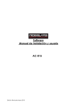
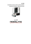
3) Using the modified RS232 cable, attach the
RS232 connector to a vacant Serial (COM)
port on the PC. Connect the wires to the
corresponding terminals, labeled RS232,
according to the following diagram.
9 PIN Female
PC Connection
AC-015 Terminals
(Labeled RS232)
Pin #5 (GND)
(-)
Pin #2 (Rx)
Tx
DOOR
1
2
3
4
5
6
7
8
9
0
#
TX
(-)
To PC Serial Port
(COM Port)
AC-015
MODE
Page 12
03/02
Software Installation Procedure
Follow these steps to install the AC-015 software:
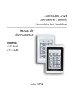
1) Insert the CD into the CD-ROM drive and
open the drive window.
2)
AC-015 application
Double-click on the
file. The following screen is displayed:
AC-015
Page 13
03/02
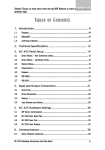
3)
The system extracts the required files and
when complete displays the next screen:
4)
5)
Click on the Next button to proceed.
Select the required file storage location, by
clicking on the Browse button, or click Next
to accept the default destination.
AC-015
Page 14
03/02
6)
Type in a new Program Folder name or
accept the default name and click Next to
continue.
7)
To make changes to the settings click
Back. To proceed with the installation click
Next.
AC-015
Page 15
03/02
8)
The progress bar shows the percentage of
installed files. This may take approximately
1 minute.
9)
Once the installation is completed
successfully, click Finish to exit.
AC-015
Page 16
03/02
Getting Started
Overview
The AC-015 Programmer is a controller that
allows you to add or delete employees from the
system, change system mode status and to
change system authorization codes.
The AC-015 provides a higher level of security as
the programmer is normally placed in a secure
location while the reader sensor is remotely
located outside the premises to be controlled.
Should the remote sensor be attacked, entry
cannot be gained as the remote sensor only
provides data to the programmer, not
authorization to release the controlled door.
The system may be connected with the optional
PC monitor program for easier management of
the employees’ database or for online monitoring
of door access. The system is linked to a PC via
an RS-232 serial link. The PC receives
information from the AC-015 that is displayed and
saved to a database. Code entries and their
consequences are visible in Online Mode of the
software. The Employees menu is used to
describe, enter and associate employee code
numbers with employee names and details. The
Programming menu is used to define door
details, working days and holidays. The Reports
menu specifies which kind of report to build.
AC-015
Page 17
03/02
The Options menu is used for communication
setup, language setup, operators’ password
setup and database status. For more details refer
to the AC-015 Single Door Access Control
Programmer.
The AC-015 accepts up to 500 employees via the
use of proximity cards (provided separately) or
entering PIN codes into the system. Each
employee is issued a unique proximity card or
PIN code.
Employees designated 01 to 10 are Master users
and can operate the system in both the Normal
and Secure modes of operation. Employees 11 to
500, when entered from the external reader
sensor, may only operate the system in either
Normal or Bypass mode.
It is very important to keep an accurate record of
the slot number and its assignment to each
employee. This is to enable you to add additional
employees at a later time or delete a Prox or PIN
code if one is lost or stolen. A record form is
enclosed for your reference to assist you with
your record keeping.
AC-015
Page 18
03/02
The AC-015 is capable of learning both PIN
codes (keyboard based codes – 4-digit code) and
Proximity codes (received from proximity card
reader). The system can be connected to up to
two reader sensors. An external reader must be
located outside the restricted area, and is
mandatory. The second reader is for internal
installation. Both readers may be Prox or PIN
type readers.
A PIN reader, connected to the indoor reader
input can perform all the operations usually done
from the on-board keyboard (depending on the
PIN reader model). A PIN reader connected to an
external reader input will behave mostly the same
but the access level is different on certain AC-015
status of operation.
AC-015
Page 19
03/02
Running the Software
Follow these steps to run the AC-015 software:
1)
On your desktop double-click on the
icon OR click on the menu path: Start >
Programs > Rosslare > AC-015.
After initiating the program, the PC will load
all databases and the following screen will
be displayed:
2)
Enter in the access password and click OK.
The default password is admin.
AC-015
Page 20
03/02
3)
The Main screen will be displayed:
See Screen Layout – page 22 for details.
AC-015
Page 21
03/02
Main Screen Layout
The AC-015 software, allows the user to perform
functions by using the drop-down menus and the
Toolbar buttons. Some functions can only be
accessed via the Menu Bar.
Menu
Bar
Toolbar
AC-015
Page 22
03/02
The Menu Bar
Three menus are accessed from the Menu Bar:
View, Tools and Help.
The View Menu
The View
commands:
Menu
contains
the
following
Commands
Description
On Line
See On Line - page 27 for
more details.
Employees
Gives details about
specified employees. See
Employees – page 29 for
more details.
Programming
Allows the user to program
door details, modes of
operation and programming
codes. See Door
Programming – page 53 for
more details.
AC-015
Page 23
03/02
Commands
Description
Reports
Accesses the various
employees’ reports. See
Reporting – page 76 for
more details.
Exit
Exits the AC-015 software.
The Tools Menu
The Tools Menu contains the following command:
Command
Description
Options
Accesses the following
options: Communication
Setup, Language, Operators
and Database Status. See
Options – page 44 for more
details.
AC-015
Page 24
03/02
The Help Menu
The Help
commands:
Menu
contains
the
following
Commands
Description
Contents
Opens the AC-015 software
online help.
Index
Opens the index of the AC015 software online help.
Technical
Support
Displays the Technical
Support information for the
AC-015 software.
About AC015
Displays the AC-015 software
version information.
AC-015
Page 25
03/02
The Toolbar
The toolbar provides shortcuts for accessing the
AC-015 commands. These commands can also
be accessed via the Menu Bar.
Following is an explanation of the available
options. For a more detailed description of the
Toolbar options see the following sections.
Tool
Choose this to
Displays the online status of the
AC-015.
Access the Employees List.
Program the Door name, Working
Days and Holidays.
Display the Reports options.
Display the AC-015 software on
line help.
Exit the AC-015 software.
AC-015
Page 26
03/02
Using the AC-015 Software
On Line
The On Line screen can be opened by selecting
View > On Line from the Menu Bar OR by
On Line icon on the Toolbar.
clicking the
The following screen is displayed:
Toolbar
Picture
Box
Data
Table
Door
Status
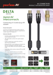
The Data Table shows details of connected door
movements, such as: door action, date and time,
employee name and In/Out reader/keyboard.
The Picture Box shows the employee’s picture
of the selected row.
If the Door Status changes, it will change the
status and the icon’s color in the screen. See
Door Programming - page 53 for more details.
AC-015
Page 27
03/02
The following options are available from the
Toolbar:
Tool
Choose this to
Print the data table.
Display the AC-015 software on line
help.
Close the On Line Screen and
return to the AC-015 software main
window.
AC-015
Page 28
03/02
Employees
The Employees List gives details about specified
employees and allows the user to add new
employees to the list and maintain current
employees in the list.
From the Menu Bar select View > Employees
OR click on the
Employees icon. The
Employees List window is displayed:
Toolbar
Employee
Table
AC-015
Page 29
03/02
The following options are available from the
Employees List toolbar: New, Delete, Edit, Print,
Help and Close.
Tool
Choose this to
Add a new employee. See Creating
a New Employee – page 32 for
more details.
Delete the selected employee.
Edit the selected employee. See
Employee Details – page 37 for
more details.
Print all the employees’ details.
Open the AC-015 software on line
help.
Close the Employees List window
and return to the AC-015 software
Main screen.
AC-015
Page 30
03/02
The Employee Table displays the following main
employee details:
Access
If an employee has access to
the factory he has access to a
PIN code or Proximity code.
Employ…
Employee number on the PC
software.
Slot#
Employee number at the Access
Control point.
AC-015
Page 31
03/02
Creating a New Employee
Every time a door is accessed the system can
identify the person that has passed through. Each
employee must therefore be “created” on the
system.
Follow these steps to create a new employee:
1) Click on the Employees icon or click on the
menu:
View
>
Employees.
The
Employees List is displayed:
AC-015
Page 32
03/02
2)
Click New to display the Employee
Details screen:
3)
Enter the required details. Refer to
Employee Details – page 37 for field
details.
AC-015
Page 33
03/02
Deleting an Employee
Follow these steps to delete an employee from
the database:
1) From the Employees List Table select an
employee to delete.
2)
Click the
employee.
displayed:
AC-015
The
Delete icon to delete an
following warning is
Page 34
03/02
3)
Click Yes if you are sure you want to delete
an employee. The employee is deleted from
the database.
Editing an Employee
Follow these steps to edit an employee’s details:
1) From the Employees List Table select an
employee to edit.
AC-015
Page 35
03/02
2)
Click the
Edit icon to display the
Employee Details screen:
3)
Enter the required details. Refer to
Employee Details – page 37 for field
details.
AC-015
Page 36
03/02
Employee Details
This screen contains all the employee’s data.
There are four tabs accessed from this screen,
which contain all the required employee and
company information, and also allow for the
creation of new codes for each employee.
Toolbar
Tabs
Browse
Buttons
AC-015
Page 37
03/02
The following options are available from the
Employees Details toolbar:
Tool
Choose this to
Save current employee data.
Save all employees’ data.
Undo the last action performed.
Print current employee data.
Access the AC-015 software on line
help.
Close the Employee Details and
return to the Employees List
window.
AC-015
Page 38
03/02
The following buttons are available from the
Employee Details window:
Button
Function
Move to first employee.
Move to previous employee.
Move to next employee.
Move to last employee.
AC-015
Page 39
03/02
The following Tabs are available:
Details Tab
Contains fields for entering the following data; ID
number, gender, family status, birthday, address,
telephone number and email.
Access Tab
AC-015
Page 40
03/02
Contains fields for entering the following data;
Access Code and Slot Number at the Access
Control. You can add or delete a Proximity card
or PIN code
Add Code
To add an access code, click on the Add Code
button. The following message is displayed:
Swipe the card over the reader or enter in a PIN
code. Once the code is accepted it will be
displayed in the slot number field.
Delete Code
To delete an access code, click on the Delete
Code button and confirm that you want the code
deleted.
AC-015
Page 41
03/02
Company Tab
Contains fields for entering the following data;
Position, employment date, position date, start
time (the official working start time) and working
hours (the official number of working hours).
Picture Tab
Allows a picture of the employee to be added or
deleted.
AC-015
Page 42
03/02
Add Picture
Click on the Add Picture button. A browse
window is displayed, in which the user can define
the location of the picture on PC or network.
Once the file has been located, select it and then
click Add. The picture will now be displayed on
the Picture Tab.
Delete Picture
To delete a picture, click on the Delete button.
AC-015
Page 43
03/02
Options
From the Menu Bar select Tools > Options. The
following window is displayed:
Choose
from
the
following
options:
Communication Setup, Language, Operators
and Database Status.
AC-015
Page 44
03/02
Selecting the Correct Serial (COM)
Port
The user is required to set the COM port setting,
which correlates to the COM port, used for the
serial cable.
Follow these steps to select the Serial (COM)
port:
1) Click on the menu path Tools > Options.
The following window is displayed:
AC-015
Page 45
03/02
2)
Click on the Communication Setup option.
The system will ask for a password. Only
Engineer operators and above may access
this setting. Enter a valid password and
click OK. The following screen is displayed:
3)
Select the required COM port that matches
the COM port on the PC to which the AC015 has been connected. Click OK to save
the settings and then click Close to exit.
The following screen is displayed:
4)
Enter a password (Administrator level only)
and click OK to exit. Finally click Close to
exit the Options window.
AC-015
Page 46
03/02
Language Selection
Use this option to change the language of the
program to any one of the supported languages.
Follow these steps to change the language
setting:
1) Click on the menu path Tools > Options.
The following window is displayed:
AC-015
Page 47
03/02
2)
Click on the Language option.
following screen is displayed:
The
3)
Select the required language from the list
and click OK to save the setting.
Operators
Use this option to grant or deny operators access
to the program’s features, and to change
passwords and other settings.
Setting Up Operators
The AC-015 support three types of system
operators each with their own access rights to
various menus and options within them. This
ensures that only certain individuals have access
rights, to change system settings.
AC-015
Page 48
03/02
The following operators may be setup:
• Guard – Access to On-line screen only
• Engineer – Allowed to change only the
COM setting
• Administrator – Allowed to change all
settings and access all screens.
The default passwords are:
• Guard – secur
• Engineer – engin
• Administrator - admin
Setting Up Operator Passwords
Follow these steps to setup an operator
password:
1) Click on the menu path Tools > Options.
The following window is displayed:
AC-015
Page 49
03/02
2)
Click on the Operators option.
following screen is displayed:
3)
Click on the Tab of the operator type, you
wish to setup, for example Guard. Click on
Password. The following dialogue box is
displayed:
4)
Complete all three fields and click OK to
save and exit.
AC-015
Page 50
The
03/02
Database Status
Use this option to periodically compact and cut
down the database. Compacting the database
improves performance. Cutting down the
database saves memory on your computer.
Follow these steps to compact and cut down the
database:
1) Click on the menu path Tools > Options.
The following window is displayed:
AC-015
Page 51
03/02
2)
Click on the Database Status option. The
following screen is displayed:
3)
To compact data click the Compact button.
The following message is displayed:
4)
To cut down data click the Cut Down
button. The following message is displayed:
5)
Click OK and click Close to exit the
Options window.
AC-015
Page 52
03/02
System Programming
Door Programming
To access the Programming screen, click on the
Programming icon or follow the menu path
View > Programming. The following window is
displayed:
AC-015
Page 53
03/02
Programming Door Details
On the first tab, labeled Door, enter in the
required information for the following fields:
• In the Company field, enter the name of
the company.
• In the Door Name field, enter a name
for the door.
The Door Status field displays the current status
of the door. The following statuses exist:
Unknown – the default status- If the
door status is unknown or door is
disconnected.
Normal Mode – A Valid Lock Strike
code (card or PIN code) is required
to gain entry. The Mode LED is
GREEN.
Secure Mode – Employee Codes
and Open Codes ½ entered through
external reader sensor are locked
out, unless they are Management
(Master) codes. All other valid
Prox/PIN codes entered from
internal reader or local keyboard will
gain entry. The Mode LED is RED.
AC-015
Page 54
03/02
Bypass Mode – For Fail Secure
operation (factory default) the door
is locked, but pressing the bell
button (* key) will release the
Locking device. The Mode LED is
ORANGE.
Programming Working Days
From the Programming window, click on the
Working Days tab.
The duration and start times for each day of the
week can be programmed.
Enter the required times and hours in the
respective fields:
AC-015
Page 55
03/02
• In the Start Time field, enter the starting
time for each workday.
• In the Working Hours field, enter the
number of hours that constitute a
workday.
Programming Holidays
Any calendar holidays may be programmed into
the system.
From the Programming window, click on the
Holidays tab.
AC-015
Page 56
03/02
To add a holiday, click on the Add button. The
following screen is displayed:
• In the Date field, enter the date on which
the holiday falls.
• In the Holiday Name field, enter the
name of the holiday.
• Click OK to save the new holiday.
• To delete a holiday from the list, simply
select it and click on the Delete button.
After a confirmation message the
holiday will be removed from the list.
AC-015
Page 57
03/02
Modes of Operation
The AC-015 has 3 Modes of Operation:
1) Normal Mode - A Valid Lock Strike code
(card or PIN code) is required to gain entry.
The Mode LED is Green.
2) Bypass Mode - For Fail Secure operation
(factory default) the door is locked, but
pressing the bell button (* key) will release
the Locking device. The Mode LED is
ORANGE.
For Fail Safe operation: Locker door is
released The Mode LED is ORANGE.
3) Secure Mode - Employee codes and Lock
Strike codes half entered through external
reader sensor are locked out, unless they
are Management (Master) codes. All other
valid Prox/PIN codes entered from internal
reader or local keyboard will gain entry. The
Mode LED is RED.
AC-015
Page 58
03/02
Changing Modes of Operation
Changing from Normal Mode to Secure Mode:
1) Enter your 4-digit Normal/Secure Code
(3838 is the default code).
2) The Mode LED will flash RED.
3) Press the # key. The Mode LED will turn
RED.
Changing from Secure Mode to Normal Mode:
1) Enter your 4-digit Normal/Secure Code
(3838 is the default code).
2) The Mode LED will flash GREEN.
3) Press the # key. The Mode LED will turn
GREEN.
Changing from Normal Mode to Bypass Mode:
1) Enter your 4-digit Normal/Bypass Code.
2) The Mode LED will flash ORANGE.
3) Press the # key. The Mode LED will turn
ORANGE.
Changing from Bypass Mode to Normal Mode:
1) Enter your 4-digit Normal/Bypass Code.
2) The Mode LED will flash GREEN.
3) Press the # key. The Mode LED will turn
GREEN.
AC-015
Page 59
03/02
REX- Request to Exit Switch:
The REX switch is used when exiting the
restricted area.
• For Door Locker Programmed as Fail
Secure operation:
Door is opened for the pre-programmed
door open time, calculated from the
moment that the REX is pressed. The
door will close even if the REX is kept
pressed.
• For Door Locker Programmed as Fail
Safe operation:
Door is opened for the pre-programmed
door open time, calculated from the
moment that the REX is released. The
door remains open for as long as the
REX is pressed plus the programmed
door open time.
AC-015
Page 60
03/02
Tamper Events
A Tamper event will cause the AC-015 Tamper
Output to open and an alarm to sound, if enabled.
A Tamper event may occur in several instances:
• AC-015 cover is removed or broken, or
the AC-015 is removed from its wall
mount.
• A reader sensor wire is being
disconnected from the AC-015 reader
input terminal.
• A tamper data signal is received from
one of the reader sensors.
Clearing Tamper Events
To clear a tamper event enter a valid employee
or Lock Strike code that will open the door locker
output at that instance. For example, during
Secure status, entering Lock Strike Code 1 from
the external reader will not clear the tamper
because it’s not permitted to open the door at this
status. However, applying the same code from
the internal reader will clear the tamper output.
AC-015
Page 61
03/02
Programming Mode
The Programming Mode is used to change the
following:
• Change Lock Strike Code 1 -Initial
Setting: 2580.
• Change Lock Strike Code 2 -No Initial
Setting.
• Change Program Code -Initial Setting:
1234.
• Change Normal/Secure Code - Initial
Setting: 3838.
• Change Normal/Bypass Code - No Initial
Setting.
• Change Door Release Time - Initial
Setting: 0004 (4 Seconds).
• Choose Fail Secure/Fail Safe - Initial
Setting fail-safe.
• Enroll Proximity Cards or PIN Codes.
• Delete Proximity Cards or PIN Codes.
• Return to default factory settings.
Note: You must be in Normal Mode to program
the AC-015. The Mode Led will be Green.
AC-015
Page 62
03/02
• Wrong or Timed Out entries will reset
the controller to Normal Mode.
• All programming operations can be done
either from the on-board or external
keyboard.
To exit programming, press the # key for two
seconds. Three beeps are sounded and the
system returns to Normal Mode. A short press on
the # key will also return the system to Normal
Mode and a long beep is heard. This aborts
programming, but in some cases, e.g.
programming function #7, data may have been
already programmed.
Changing Lock Strike Code 1
1)
2)
3)
4)
Press # for 2 seconds. There will be a
long beep and the Mode LED will turn OFF.
The door LED will be RED.
Enter your 4-digit programming code.
(1234 is the initial programming code) The
Door LED will turn GREEN. The Mode LED
will turn OFF.
Press 1. The Door LED will remain GREEN
and the MODE LED will turn RED.
Enter the new 4-digit code you wish to
set as lock strike code 1. There will be 3
beeps and the system will return to
NORMAL MODE.
AC-015
Page 63
03/02
Changing Lock Strike Code 2
1)
2)
3)
4)
Press # for 2 seconds. There will be a
long beep and the Mode LED will turn OFF.
The door LED will be RED.
Enter your 4-digit programming code.
(1234 is the initial programming code) The
Door LED will turn GREEN. The Mode LED
will turn OFF.
Press 2. The Door LED will remain GREEN
and the MODE LED will turn ORANGE.
Enter the new 4-digit code you wish to
set as lock strike code 2. There will be 3
beeps and the system will return to
NORMAL MODE.
Changing Programming Code
1)
2)
3)
Press # for 2 seconds. There will be a
long beep and the Mode LED will turn OFF.
The door LED will be RED.
Enter your 4-digit programming code.
(1234 is the initial programming code) The
Door LED will turn GREEN. The Mode LED
will turn OFF.
Press 3. The Door LED will remain GREEN
and the MODE LED will turn GREEN.
AC-015
Page 64
03/02
4)
Enter the new 4-digit code you wish to set
as the new programming code. There will
be 3 beeps and the system will return to
NORMAL MODE.
Note: The Programming code cannot be erased.
Changing Bypass Code
Note: The Normal/ Bypass code also controls the
Chime function for the AC-015. There are 4
options this code may be set for:
1) Press # for 2 seconds. There will be
a long beep and the Mode LED will
turn OFF. The door LED will be RED.
2) Enter your 4-digit programming
code. (1234 is the initial programming
code) The Door LED will turn
GREEN. The Mode LED will turn
OFF.
3) Press 5. The Door LED will remain
GREEN and the MODE LED will flash
ORANGE.
AC-015
Page 65
03/02
There are 4 options this code may be set for:
1) Option 1: Disable Bypass Mode –
Disable Chime:
Enter 0000. This will disable both Bypass
Mode function and chime function. There
will be 3 beeps and the system will return to
NORMAL MODE.
2) Option 2: Disable Bypass Mode – Enable
Chime:
Enter 0001. This will disable Bypass Mode
function and enable chime function for
Normal Mode. There will be 3 beeps and
the system will return to NORMAL MODE.
3) Option 3: Enable Bypass Mode – Disable
Chime:
Enter a 4-digit code ending with the digit
0. This will enable Bypass Mode function
and disable chime function for Normal
Mode. There will be 3 beeps and the
system will return to NORMAL MODE.
4) Option 4: Enable Bypass Mode – Enable
Chime:
Enter a 4-digit code ending with any
digit except 0. This will enable Bypass
Mode function and enable chime function
for Normal Mode. There will be 3 beeps and
the system will return to NORMAL MODE.
AC-015
Page 66
03/02
Changing Secure Code
1)
2)
3)
4)
Press # for 2 seconds. There will be a
long beep and the Mode LED will turn OFF.
The door LED will be RED.
Enter your 4-digit programming code.
(1234 is the initial programming code) The
Door LED will turn GREEN. The Mode LED
will turn OFF.
Press 4. The Door LED will remain GREEN
and the MODE LED will flash RED.
Enter the new 4-digit code you wish to
set as the Normal/Secure Change code.
There will be 3 beeps and the system will
return to NORMAL MODE.
Changing Door Release Time
1)
2)
3)
Press # for 2 seconds. There will be a
long beep and the Mode LED will turn OFF.
The door LED will be RED.
Enter your 4-digit programming code.
(1234 is the initial programming code) The
Door LED will turn GREEN. The Mode LED
will turn OFF.
Press 6. The Door LED will remain GREEN
and the MODE LED will flash GREEN.
AC-015
Page 67
03/02
Note: This is a 4-digit code. The first digit
signifies if the unit is to be used for Fail
Secure (factory default setting) or fail safe
operation. The second digit signifies the
length of time, in minutes, the tamper
alarm will sound. The last 2 digits signify
the time the door release will be activated.
(From 01 to 99 seconds).
• For Fail Secure operation:
Enter 0 for the first digit.
• For Fail Safe operation:
Enter 1 for the first digit.
• For Tamper Alarm:
If the Tamper Alarm is required, enter 1
– 9 at the second digit to set the alarm
sound time from a minute to 9 minutes.
If Tamper Alarm is not required, enter 0
at the second digit.
• For Door Release Time:
Enter the number of seconds you want
the door release to remain activated.
(For example 0512 means Fail Secure
with a 5-minute tamper alarm sound
time and a 12-second door release).
There will be three beeps and the
system will return to Normal Mode.
AC-015
Page 68
03/02
Enrolling Proximity Cards / PIN
Codes
Each Proximity Card is unique and only can be
assigned to one slot at any time. If an unassigned
Proximity card is enrolled to an occupied slot, the
AC-015 will generate a long beep and wait for
another slot number to be entered. The card at
the current slot location must first be erased
before a new code is programmed on that slot
number. The same rules apply for PIN based
Employee Codes.
1) Press # for 2 seconds. There will be a
long beep and the MODE LED will turn
OFF. The DOOR LED will be RED.
2) Enter your 4-digit programming code.
(1234 is the initial programming code) The
DOOR LED will turn GREEN. The MODE
LED will turn OFF.
3) Press 7. The MODE LED will turn GREEN
and the DOOR LED will turn ORANGE.
4) Enter the 3-digit slot code you wish to
assign to the system employee. For
Example 003 represents slot “3”. The
DOOR LED will remain ORANGE and the
MODE LED will start flash GREEN.
AC-015
Page 69
03/02
5)
6)
7)
8)
Present the Proximity Card designated
for this slot number to the reader. The
unit will beep once and the MODE LED will
stop flashing. Or, enter the 4-digit PIN
employee code designated for this slot
number. The unit will beep once and the
MODE LED will stop flashing.
To enroll another card, enter the 3-digit
slot code you wish to assign to the next
system employee. The MODE LED will
start flashing.
Present the Proximity Card designated
for this slot number to the reader. The
unit will beep once and the MODE LED will
stop flashing. Or, enter the 4-digit PIN
employee code designated for this slot
number to the reader. The unit will beep
once and the MODE LED will stop flashing.
Continue enrolling cards or entering PIN
codes in this manner until all system
employee codes are entered.
Note: The AC-015 programmer will not
accept System Employee Codes
that are already allocated to a slot.
The AC-015 will signal this with a
long beep and the Door Led will
continue to flash GREEN.
When finished enrolling cards, press the #
key. There will be a long beep and the AC015 will return the to NORMAL MODE.
AC-015
Page 70
03/02
Note: If the programming period times out
before you press the # key the
controller will return to Normal Mode.
Any enrolled codes in this period will
remain valid.
Deleting Proximity Cards / PIN
Codes
1)
Press # for 2 seconds. There will be a
long beep and the MODE LED will turn
OFF. The DOOR LED will be RED.
2) Enter your 4-digit programming code.
(1234 is the initial programming code) The
Door LED will turn GREEN. The Mode LED
will turn OFF.
3) Press 8. The MODE LED will remain
GREEN and the DOOR LED will turn
ORANGE.
4) Enter the 3-digit slot code you wish to
delete from the system. For example 003
represents slot “3”. There will be 2 beeps
and the MODE LED will start to flash RED.
5) Enter the 4-digit programming code (this
last step confirms that you intentionally
want to delete an employee from the
system). The system will then revert back to
NORMAL MODE.
If additional cards/ PIN codes need to be deleted
then repeat steps 1-5.
AC-015
Page 71
03/02
Note: Ensure that your record of system
employees and their assigned system
card slot numbers is stored in a secured
location. Then if you wish to delete a slot
stolen Employee Code from the system
you can identify the card from your
record.
Return to Factory Settings and
Facility Code
IMPORTANT: You must be very careful before
using this command! Doing so will
erase the entire memory which
includes all employee and special
codes. All Preprogrammed Cards,
PIN codes and special codes will
have to be reprogrammed from
the beginning.
1) Press # for 2 seconds. There will be a
short beep and the MODE LED will turn
OFF. The DOOR LED will be RED.
2) Enter your 4-digit Programming Code.
(1234 is the initial Programming Code) The
DOOR LED will turn GREEN. The MODE
LED will be OFF.
3) Press 0. The DOOR LED will flash RED
and the MODE LED will remain OFF.
AC-015
Page 72
03/02
For Return to factory programming:
4) Press 0 again. The DOOR LED will
continue flashing RED and the MODE LED
will flash RED.
5) Enter your 4-digit programming code
(this last step confirms that you intentionally
want to delete all your initial settings and
employee codes from the system!).
You will hear 3 beeps and the system will
return to Normal mode
For Facility code programming:
4) Press 1. The DOOR LED will continue
flashing RED and the MODE LED will flash
GREEN.
5) Enter your 3-digit Facility Code, which
must be between 0-255. The MODE LED
will turn GREEN. If the wrong code is
entered the system will exit programming
mode.
6) Enter your 4-digit programming code
(this last step confirms that you intentionally
want to delete all your initial settings and
employee codes from the system!).
You will hear 3 beeps and the system will
return to Normal mode
AC-015
Page 73
03/02
IMPORTANT:
• Facility Code 000 means that any
Proximity card can be learned, with any
Facility Code.
• It is recommended to program Facility
Code once before programming any
employee codes. Changing Facility
Code after codes are programmed will
cause previous codes with different
Facility Codes to disappear while still
occupying the code slot number.
• If the Facility Code is not 000,
programming any Proximity Card with
another Facility Code is prohibited.
However, PIN codes are not affected.
AC-015
Page 74
03/02
Replacing Lost Programming Codes
In the event that a Programming Code is lost, the
AC-015 may be reprogrammed by following these
instructions:
In Normal Mode:
1) Disconnect the power from the AC-015.
2) Depress the Internal Door Release
(Request to exit) button.
3) Reconnect the power to the unit with the
Door Release button depressed.
4) Release the Door Release button.
5) You now have 20 seconds to program a
new Programming Code into the unit using
the initial default code 1234, before the
controller reverts to the existing code.
In Secure Mode:
1) Disconnect the power from the AC-015
2) Press the Internal Door Release button.
3) Reconnect the power to the unit with the
Door Release button depressed.
4) Release the Door Release button.
5) You now have 20 seconds to use the
default code 3838 to return the system back
to NORMAL MODE. Then use the
programming instructions for a controller in
NORMAL MODE, as above, to reset the
programming code.
AC-015
Page 75
03/02
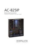
Reports
Defining Reports
To access the Reports window click on the
Reports icon, or follow the menu path View >
Reports. The following screen is displayed:
Toolbar
Report
List
Employees
Filter
Date Filter
The Reports option allows the user to run reports
according to type and sort it according to date
and employees.
AC-015
Page 76
03/02
The Toolbar
The following options are available from the
Reports Toolbar:
Tool
Choose this to
Display the report results on the
screen.
Save the report as text file.
Print the report.
Access the AC-015 software on line
help.
Close the Reports window and
return to the AC-015 software main
screen.
AC-015
Page 77
03/02
Employees Filter
The Employees Filter reports can give details
about specified employees.
Select All Employees button - fills
employees filter with all employees
(1 - 500).
Remove All Employees buttonclears the employees’ filter.
Date Filter
The reports can give details about specifies dates
and sorted in ascending or descending order you can choose the sort with the option box. You
can limit the date in the report with date filter (the
default is from one week ago until the present
day).
AC-015
Page 78
03/02
Report List
Select a Report from the Report List. You may
choose from the following reports:
Online Report
Displays the Online movement of the employees.
You can limit the data by using the date filter or
employees’ filter. In the sorting frame you can
choose the sorting order.
The report displays the following fields:
• Name – employee’s number, last name
and first name.
• Date
• Time
• In or out of the building.
• PIN code or Proximity card.
• Door Action – whether the door was
opened or not.
AC-015
Page 79
03/02
Absence Report
Presents the employees who were absent from
work. You can limit the data by using date or
employees filter.
In the sorting frame you can choose the sorting
order. The report will ignore holidays and
Saturday if it’s defined in the Programming form.
The report displays the following fields:
• Name - employee's number, last name
and first name.
• Date
AC-015
Page 80
03/02
Working Hours Details Report
Displays the number of hours the employee
worked and the time he entered and left the
factory. You can limit the data by using the date
filter or employees’ filter.
The report displays the following fields:
• Name – employee’s number and name.
• Date
• Time
• In – entered the building.
• Out - left the building.
• Sub Total - presents the sub total of
each entry and exit.
AC-015
Page 81
03/02
Incomplete Hours Report
Presents the employees that worked fewer hours
then they should have worked. The Official
Working hours are defined in the Employee
Details form. If this field is empty the data will be
taken from the ‘Doors Information’ form in the
‘working hours’ field. You can limit the data by
using the date filter or employees’ filter.
The report displays the following fields:
• Name – employee’s number and name.
• Date
• Schedule hours - the official hours the
employee should work.
• Actual hours - the number of hours the
employee actually worked.
• Missing hours - the difference between
actual hours to schedule hours.
• Global hours - total working hours that
same day from the first time the
employee arrived until the last time he
left the building.
AC-015
Page 82
03/02
Late Arrival Report
Presents the employees who arrived late to work.
You can limit the data by using the date or
employee filter.
In the sorting frame you can choose the sorting
order. The Official Start time of each employee is
defined in the Employee Details form in the
Programming frame. If this field is empty, the
official start time will be as defined in the
programming form. The default time is 08:00 AM
but it can be changed.
The report displays the following fields:
• Name – employee’s number, last name
and first name.
• Date
• Start Schedule - the official start time.
• Start Actual - the time the employee
actually arrived at work.
• Late – number of hours/minutes late.
AC-015
Page 83
03/02
Working Hours Total Report
Presents a summary of the Working Hours
Details report. You can limit the data by using the
date filter or employee filter. The report displays
the following fields:
• Name - employee's number and name.
• Date
• Actual Hours - presents the total hours
worked that day.
• Global Hours - the time from first time
in to last time out each day.
AC-015
Page 84
03/02
Unauthorized Report
Presents employees who tried to enter but the
door did not open for some reason, and unknown
people who entered through the door. You can
limit the data by using the date filter. Employees
filter is not enabled because this report includes
all movements. In the sorting frame you can
choose the sorting order.
The report displays the following fields:
• Date
• Time
• Name - employee’s number and name.
• Slot# - slot number at Access Control
• Code# - PIN code or Proximity card.
• Door Action - if the door opened or not.
• Reason - the reason the door didn't
open.
AC-015
Page 85
03/02
AC-015
Page 86
03/02
Technical Support
International Web Site:
http:///www.rosslare.com.hk/support/
Asia, Australia, & South America:
Rosslare Enterprises Ltd.
905-912 Wing Fat Industrial Bldg.,
12 Wang Tai Road, Kowloon Bay
Hong Kong
Tel:
(852) 2795 5630
Fax:
(852) 2795 1508
E-mail: [email protected]
Europe, Russia, Middle East, Africa:
Rosslare Security Products S.r.l
Via F.lli Gabba 5, 20121 Milano, Italy
Tel:
(39) 0382 24800
Fax:
(39) 0382 24800
E-mail: [email protected]
[email protected]
United States and Canada:
Rosslare NAPDC
200 East Howard Street, Suite 238,
Des Plaines, IL 60018
USA
Tel:
(847) 827 6330
Fax:
(847) 827 6433
E-mail: [email protected]
AC-015
Page 87
03/02
9J-IDR-028 / 0706-0820028-00
www.rosslare.com.hk