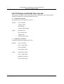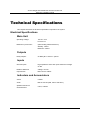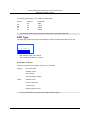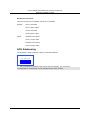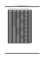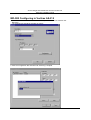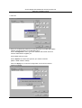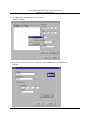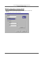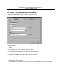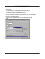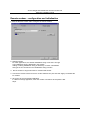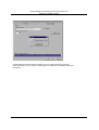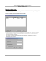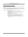
1
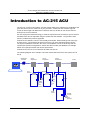
AC-215
Single and Double Door
Access Control Unit
Hardware Installation Guide
April 2004
Copyright and Version Number
Information in this document, including URL and other Internet Web site references, is
subject to change without notice. Unless otherwise noted, the example companies,
organizations, products, people and events depicted herein are fictitious and no
association with any real company, organization, product, person or event is intended
or should be inferred.
© Copyright 2003 Rosslare. All rights reserved.
Rosslare, the Rosslare logo, and the Rosslare products referred to herein are either
the trademarks or registered to the trademarks of Rosslare, All other trademarks are
the property of their respective owners.
Software License Agreement.
ROSSLARE IS WILLING TO LICENSE THE ENCLOSED SOFTWARE ONLY ON THE
CONDITION THAT YOU ACCEPT ALL OF THE TERMS CONTAINED IN THIS
LICENCE AGREEMENT. This is a legal agreement between you (either the individual
or the end-user or an entity) and Rosslare. By opening this software package, you are
agreeing to be bound by the terms and conditions of this Agreement. If you do not
agree to the terms of this Agreement, promptly return the software package and other
items that are part of this product in their original package with your payment receipt to
your point of purchase for a full refund. Grant of License. Rosslare and its suppliers
grant you a nonexclusive license to use one copy of the enclosed software program
(”Software”) on one computer with the Rosslare product you have purchased. No other
rights are granted. The software is in use if it is loaded on the computer’s permanent
or temporary memory. For backup purposes only you may make one copy of the
Software. You must include on the backup copy all copyright and other notices
included on the Software as supplied by Rosslare. Installation on a Network server for
the sole purpose of your internal distribution of the Software is permitted only if you
have purchased an individual software package for each networked computer to which
the software is distributed. Restrictions. Rosslare and its suppliers retain ownership of
the Software. You may not decompile, disassemble, reverse engineer, or modify the
Software in any way. You may not transmit the software over a network (except as
expressly permitted above), by telephone, or electrically using any means. You may
not transfer the Software except upon a permanent transfer of the enclosed Rosslare
product provided that all software updates are included in the transfer, you do not
retain a copy of the Software, and the transferee agrees to be bound by the terms and
conditions of this license. Upon any violation of any of the provisions of this
Agreement, rights to use the Software shall automatically terminate and the Software
must be returned to Rosslare or all copies of the Software destroyed. Limited Product
Warranty. Rosslare warrants that any hardware products accompanying this
documentation shall be free from significant defects in material and workmanship for a
period of one year from the date of purchase. Rosslare also warrants that the Software
accompanying this documentation will perform substantially in accordance with the
documentation for a period of 90 days from purchase. Rosslare’s hardware and
software warranty is nontransferable and is limited to the original purchaser. Product
Remedies. Rosslare’s entire liability and the licensees exclusive remedy for any
breech of warranty, shall be, at Rosslare’s sole option, either a) return the price paid or
b) repair or replacement of hardware or software, provided that the hardware is
returned to the point of purchase, with a copy of the sales receipt. Any replacement
hardware and software will be warranted for the remainder of the original warrantee
period or 30 days for the hardware and 30 days for the software, whichever is longer.
The remedies are void if failure of the software or hardware has resulted from abuse,
accident or misapplication.
Limitation of Liability
THE WARRANTIES SET FORTH IN THIS AGREEMENT REPLACE ALL OTHER
WARRANTIES. ROSSLARE EXPRESSLY DISCLAIMS ALL OTHER WARRANTIES,
INCLUDING BUT NOT LIMITED TO, THE IMPLIED WARRANTIES OF
MERCHANTABILITY AND FITNESS FOR A PARTICULAR PURPOSE AND NONINFRINGEMENT OF THIRD PARTY RIGHTS WITH RESPECT TO THE
DOCUMENTATION, SOFTWARE, AND HARDWARE. NO ROSSLARE DEALER,
AGENT, OR EMPLOYEE IS AUTHORISED TO MAKE ANY MODIFICATION,
EXTENSION, OR ADDITION TO THIS WARRANTY. IN NO EVENT WILL
ROSSLARE OR IT”S SUPPLIERS BE LIABLE FOR ANY COSTS OF
PROCUREMENT OF SUBSTITUTE PRODUCTS OR SERVICES, LOST PROFITS,
LOSS OF INFORMATION OR DATA, OR ANY OTHER SPECIAL DIRECT OR
INDIRECT, CONSEQUENTIAL, OR INCIDENTAL DAMAGES ARISING IN ANYWAY
OUT OF THE SALE, OF, USE OF, OR INABILITY TO USE ANY ROSSLARE
PRODUCT OR SERVICE, EVEN IF ROSSLARE HAS BEEN ADVISED OF THE
POSSIBILITY OF SUCH DAMAGES. IN NO CASE SHALL ROSSLARE’S LIABILITY
EXCEED THE ACTUAL MONEY PAID FOR THE PRODUCTS AT ISSUE. Because
some jurisdictions do not allow the implementation of limited warranties or liability for
incidental, consequential, special, or indirect damages, the above limitation may not
always apply. The above limitations will not apply in case of personal injury where and
to the extent that applicable law requires such liability.
U.S. Government Restricted Rights
The software is provided to the U.S. Government only with restricted rights and limited
rights of use, duplication or disclosure by the U.S. Government is subject to
restrictions set forth in 48 C.F.R 2.101 (Oct 1995) consisting of “Commercial Computer
Software” and “Commercial Computer Software Documentation” as such terms are
used in 48 C.F.R. 12.212 (September 1995), and in FAR Sections 52-227-14 and 52227-19 or DFARS Section 52.227-7013 (C) (ii), or their successors, as applicable.
Consistent with 48. C.F.R. 12.212 and 48 C.F.R. 227.7202-1 through 227.7204-1
(June 1995), or any successor regulations, this software is provided to the terms and
conditions herein. Contractor/ Manufacturer Rosslare Enterprises Ltd. 12 Wang Tai
Road, Hong Kong
AC-215 Single and Double Door Access Control Unit
Hardware Installation Guide
Table of Contents
Introduction to the AC-215 ACU ...................................................................................... 1
Main Features..................................................................................................................................................2
Software ...........................................................................................................................................................4
Technical Specifications................................................................................................... 5
Electrical Specifications ..................................................................................................................................5
Inputs and Outputs ............................................................................................................ 7
Inputs ...............................................................................................................................................................7
Outputs.............................................................................................................................................................8
Readers .........................................................................................................................................................10
Dipswitch Settings Configuration ................................................................................. 11
Single Door Controller ..............................................................................................................................12
Double Door Controller.............................................................................................................................13
Communications .............................................................................................................. 15
RS232 Connection to the PC...................................................................................................................15
RS485 Connection to the PC...................................................................................................................16
Communication through Modem..............................................................................................................17
Communication through the Local Area Network (LAN)........................................................................18
Wiring ................................................................................................................................ 19
Accesories ........................................................................................................................ 23
Appendix ........................................................................................................................... 26
Appendix A - Connecting Between MD-N32 and AC-215 .....................................................................26
Appendix B - Connecting Between MD-N33 and AC-215 ................................................................... .31
Power Supply Specifications ......................................................................................... 39
Technical Support ........................................................................................................... 40
i
AC-215 Single and Double Door Access Control Unit
Hardware Installation Guide
About this manual
This manual is intended for anybody installing and or commissioning the AC-215
access control system.
! We recommend that this manual be read in full before the Veritrax AS-215 software
and AC-215 Access Control System installed.
ii
AC-215 Single and Double Door Access Control Unit
Hardware Installation Guide
Introduction to AC-215 ACU
The AC-215, access control system, and the Veritrax AS-215 PC software are combination that
gives full control over the entrances of your premises. Veritrax AS-215 software supports
control for both single and double door entrances where up to 255 AC-215 Access Control
Units (ACU) can be monitored.
AC-215 employs the latest technology to meet the requirements of the market. Up to 510 doors
and 5000 users can be supported using the Veritrax AS-215 software. The product’s flash
memory enables easy firmware upgrades.
Veritrax AS-215 software, which is user friendly and intuitive, defines settings and event logs.
A single server, communicating to and from the ACU, can serve unlimited network clients.
The system’s database is saved in the server. The database can be set to backup and can
import/export previous configurations. Clients are able to modify the database, for example,
define new employees and/or their access permissions.
Veritrax AS-215 can be run on Windows 98, 2000, NT and XP.
The following diagram is an example of how the Veritrax AS-215 and AC-215 system can be
set up.
RS485/232
Converter
RS232
AC215
Single Door
RS485
AC215
Double Door
AC215
Single Door
RS485
AC215
Up to 32 ACUs
RS485
Maglock
Door
Monitor
Exit
button
Reader
Door 1
Reader,
Keypad
&
Door
Release
2 readers
for
Reader In
&
Reader
Out
Door 2
Door 3
Exit
button
Reader,
Keypad
&
Door
Release
Door 4
1
AC-215 Single and Double Door Access Control Unit
Hardware Installation Guide
Main Features
AC-215
!
Two IN/OUT readers
!
Four Inputs
!
Four Outputs
!
Optional secure mode that requires card and PIN entry
!
Antipassback real and time with forgive feature
!
Up to 4 different site codes
!
Automatic operation by time zone for every output
!
Optional first person delay before automatic door unlocking
!
Optional expanded lock operation time
!
Activated auxiliary output by reader transactions or authorized users
!
Door and panel Alarms - door forced , door held open, door held open alert and tamper
alarm
!
Programmable relock when opening/closing doors
!
Man trap door in double door configuration
!
Built in sounder generator for chime, bell and siren signals
System
!
Up to 255 ACU
!
Up to 8 networks
!
Up to 32 ACU in every network (64 doors in every network)
!
5000 users
!
5000 log events
!
64 holidays (copied from MS Outlook – option)
!
32 time zones
!
128 access groups
2
AC-215 Single and Double Door Access Control Unit
Hardware Installation Guide
AC-215 Single and Double Door Access
The access to an entrance is first set as either single or double door in the Veritrax AS-215
software, this definition is then downloaded to the panel.
"
Single Door Controller
This access type has two readers, IN or OUT
Outputs:
Door lock strike
Auxiliary output
Alarm output
General purpose output
Inputs:
Release to exit
Door monitor input
Tamper input
General purpose input
"
Double Door Controller
This access type has two readers, IN or OUT
Outputs:
Door 1 lock strike
Door 1 alarm output
Door 2 lock strike
Door 2 alarm output
Inputs:
Release to exit door1
Door 1 monitor input
Release to exit door 2
Door 2 monitor input
3
AC-215 Single and Double Door Access Control Unit
Hardware Installation Guide
Software
Veritrax AS-215 software is user friendly and intuitive. Its graphic interface is used to define
settings, which are downloaded to the ACU and event logs which are uploaded to the PC to
generate reports. A single server, which communicates to and from the ACU, can serve
unlimited network clients.
The system’s database is saved in the server. The database can be set to backup and can
input/export previous configurations. Clients are able to modify the database, for example,
define new employees and their access permissions.
The software enables features to be added as and when they are required. The modular
software enables the user interface to be as powerful and strong as required and yet remains
simple to use. The software can be set for automatic backup on a periodic basis.
Veritrax AS-215 can be run on Windows 98, 2000, NT and XP.
4
AC-215 Single and Double Door Access Control Unit
Hardware Installation Guide
Technical Specifications
This chapter discusses the technical specification required for the system.
Electrical Specifications
Main Unit
Operating Voltage:
12V DC 0.5A
From PS-14
Maximum Input Current:
(Not including attached devices)
Standby: 125mA
Maximum: 325mA
Outputs
Relay Outputs:
5A Relay N.O. and N.C. options
Inputs
General Inputs:
High impedance active low inputs. Maximum voltage:
5V DC
Reader's Electrical
requirements:
Voltage: 12V DC
Max Current: 300mA
Indicators and Annunciators
Visual:
8 LEDs
Audio:
Built in sounder (Bell, Chime and Siren)
Speaker's Electrical
Characteristics:
8 ohm, 750mW
5
AC-215 Single and Double Door Access Control Unit
Hardware Installation Guide
Environmental Specifications
Operating Temperature:
-25°F to 145°F (-31°C to 63°C)
Operating Humidity:
0 to 95% (Non-condensing)
Mechanical Specifications
Enclosure's Dimensions:
10.4” (264mm) L x 13.2” (334mm)
W x 3.4” (84.5mm) D
Weight:
8.31 lbs (3.77 kg)
6
AC-215 Single and Double Door Access Control Unit
Hardware Installation Guide
Inputs and Outputs
This chapter discusses the AC-215 ACU input and output requirements.
Inputs
Release to Exit Button (REX)
REX enables quick exit from a premises. The following should be defined:
Single door controller:
Door 1 - IN1
Double door controller:
Door 1 - IN 1
Door 2 - IN 2
Usually the REX input is connected to a push button that is located inside the premises. The
push button opens a door without reading a proximity card or PIN code.
Generally, the REX is located in a convenient position, for example, near Reception, and is
always set as enabled in the Veritrax AS-215 software.
Door Monitor
The Door Monitor connects to a door’s micro switch for door status monitoring. The following
should be defined:
Single door controller:
Door 1 - IN1A
Double door controller:
Door 1 - IN 1A
Door 2 - IN 2A
Two alarm states can be generated:
!
Forced alarm- When the door is forcibily opened by unauthorized persons
!
Door held open alarm- When the door is open for a period exceeding the lock strike
programmed open time
A Door held open alert can be generated by activating chime on speaker to remind that the
door should be close.
After the ACU enables access, the lock is activated according to its programmed time until one
of the following occurs:
!
The ACU stops lock activation immediately after the door opens
!
The ACU waits for the door to close. (This can help to reduce tailgating)
When the door open time period expires the ACU ends lock activation.
7
AC-215 Single and Double Door Access Control Unit
Hardware Installation Guide
Tamper
The Tamper input connects to a tamper micro switch assembled within the ACU panel. The
following should be defined:
Single door controller:
Door 1 – IN2
Tamper input is activated when the panel is opened through vandalism. The system has two
additional tamper inputs on the reader terminals.
General
The General input connects to any general-purpose dry contact input.
Single door controller:
Door 1 – IN2A
This function can be used when activating the general-purpose output connections (for
example, alarm sensors, monitoring power supply failure, etc.). The ACU reports activation if
this input changes status.
The system has four output relays. Their contacts are voltage free and rated 5A at 12V AC or
DC. This indicates that output is very versatile and can operate virtually any electrical
equipment including Fail Open and Fail Close locks, electric gates and so on.
Outputs
We recommend using a suppression diode for all outputs.
Door Lock
There are two types of door locking devices:
!
Fail open (fail secure)
!
Fail close (fail safe)
! The user can select either normally open or normally closed output contacts.
The following should be defined:
Single door controller:
Door 1 – OUT1
Double door controller:
Door 1 – OUT1
Door 2 – OUT2
The output can sink current from any power supply (see page 39). In a time zone door locking
is activated in the following modes:
!
Grant Access
!
Automatic Relock
8
AC-215 Single and Double Door Access Control Unit
Hardware Installation Guide
Door Alarm
This output is activated when either an alarm occurs in the system, or automatically by a time
zone. The following should be defined:
Single door controller:
Door 1 – OUT1A
Double door controller:
Door 1 – OUT1A
Door 2 – OUT2A
The output can be activated for a specified time and closes when the timer ends
Auxiliary
This output is activated when a transaction occurs in the readers that are either associated
with auxiliary, or automatically by a time zone. The following should be defined:
Single door controller:
Door 1 – OUT2
The output has two activations modes:
!
Time – active for a specified time and closes when the timer ends.
!
Toggle – active for every change in the output trigger. The trigger changes state.
General
This output is usually related to the general input or automatically by a time zone. The
following should be defined:
Single door controller:
Door 1 – OUT2A
The output has three activation modes:
!
Follow input – output follows the input state
!
Toggle – active for every change in the output trigger. The trigger changes state
!
Time – active for a specified time and closes when the timer ends
9
AC-215 Single and Double Door Access Control Unit
Hardware Installation Guide
Card Readers
Two card readers can be connected to the ACU. The following should be defined:
Single door controller:
Door 1 – Reader 1 IN/OUT/auxiliary
Reader 2 IN/OUT/auxiliary
Double door controller:
Door 1 – Reader 1 IN/OUT
Door 2 – Reader 2 IN/OUT
The readers can be assigned to a single or double door controller’s door as an IN or OUT
reader and can activate the auxiliary output in a single door configuration.
The reader’s tamper connects to the ACU and can generate an alarm. The reader’s green
LED input is activated by the ACU when in the Card and PIN secure mode to inform the user
to enter his personal PIN number after entering his card.
Keypad
Two keypads can be alternatively connected to the ACU on Reader1 and Reader2 terminals.
The following should be defined:
Single door controller:
Door 1 Keypad - Reader 1 IN/OUT
Keypad - Reader 2 IN/OUT
Double door controller:
Door 1 Keypad - Reader 1 IN/OUT
Door 2 Keypad - Reader 2 IN/OUT
The keypad type must be a Rosslare format keypad.
A keypad has to be connected for any reader mode that requires PIN code entries, such as
Card or PIN, PIN only or Card and PIN (Secured mode).
10
AC-215 Single and Double Door Access Control Unit
Hardware Installation Guide
Dipswitch Settings
Configuration
The ACU Dipswitch controls a number of operating parameters including the device address
and baud rates for serial communication.
1 2 3 4 5 6 7 8
! Power down the ACU before making changes in the dipswitch settings. Restart the ACU
after modifications are made. The new settings are automatically defined after power up.
The following is a list of dipswitch numbers and their functions:
Dipswitch
Function
1-2
Set ACU baud rate
3
Sets ACU type (single door or double door controller)
4-8
Set ACU address
ACU Baud Rate
The ACU serial port baud rate, set in dipswitches one and two, defines the communication
speed for connecting with a PC in a network connection.
1 2 3 4 5 6 7 8
11
AC-215 Single and Double Door Access Control Unit
Hardware Installation Guide
The following lists switch 1 and 2 status and baud rate:
Switch 1
Switch 2
Baud Rate
Off
Off
On
On
Off
On
Off
On
9600
19200
38400
57600
!
The ACU baud rate must be identical to the host PC’s serial port baud rate
ACU Type
The ACU type is defined using the third dipswitch. Both the single and double can be set.
1 2 3 4 5 6 7 8
!
Off - defines single door controls
!
On - defines a double door controls
Single Door Controller
This access type has two readers, IN and OUT, as follows:
Outputs:
Door lock strike
Auxiliary output
Alarm output
General purpose output
Inputs:
Release to exit
Door monitor input
Tamper input
General purpose input
!
For more information refer to the Input Output chapter, page 7.
12
AC-215 Single and Double Door Access Control Unit
Hardware Installation Guide
Double Door Controller
This access type has two readers, IN and OUT, as follows:
Outputs:
Door 1 lock strike
Door 1 alarm output
Door 2 lock strike
Door 2 alarm output
Inputs:
Release to exit door1
Door 1 monitor input
Release to exit door 2
Door 2 monitor input
ACU Addressing
The dipswitch is used to select the binary coded ACU address.
1 2 3 4 5 6 7 8
! The ACU address is defined in the Veritrax AS-215 software. For successful
communications, the dipswitch must be defined with the same address.
13
AC-215 Single and Double Door Access Control Unit
Hardware Installation Guide
The following table gives all the 32 dipswitch settings available.
Address
Switch 4
Switch 5
Switch 6
Switch 7
Switch 8
1
2
3
4
5
6
7
8
9
10
11
12
13
14
15
16
17
18
19
20
21
22
23
24
25
26
27
28
29
30
31
32
Off
Off
Off
Off
Off
Off
Off
Off
Off
Off
Off
Off
Off
Off
Off
On
On
On
On
On
On
On
On
On
On
On
On
On
On
On
On
On
Off
Off
Off
Off
Off
Off
Off
On
On
On
On
On
On
On
On
On
Off
Off
Off
Off
Off
Off
Off
Off
On
On
On
On
On
On
On
On
Off
Off
Off
Off
On
On
On
On
Off
Off
Off
Off
On
On
On
On
Off
Off
Off
Off
On
On
On
On
Off
Off
Off
Off
On
On
On
On
Off
Off
On
On
Off
Off
On
On
Off
Off
On
On
Off
Off
On
On
Off
Off
On
On
Off
Off
On
On
Off
Off
On
On
Off
Off
On
On
Off
On
Off
On
Off
On
Off
On
Off
On
Off
On
Off
On
Off
On
Off
On
Off
On
Off
On
Off
On
Off
On
Off
On
Off
On
Off
On
14
AC-215 Single and Double Door Access Control Unit
Hardware Installation Guide
Communications
Communication lines are used to upload and download information between the ACU and the
Veritrax AS-215 software. Communication between the ACU and PC is displayed by the
system’s two LEDs.
!
The RX LED flashes when the controller receives data
!
The TX LED flashes when the controller transmits data
! The ACU address is defined in the Veritrax s AS-215 software. For successful
communications, the dipswitch must be defined with the same address.
There are three connection modes:
!
Serial
" RS232
" RS485
!
Modem
!
LAN
Serial Connection
The PC Serial Port controlling the ACU is assigned in the Network Properties in the Veritrax
AS-215 software. By default the default is set to 9600 for direct connection to the PC using the
standard RS232 interface.
"
RS232 Connection
ACU
DB9 Connector
DB25 Connector
GND
Pin 5
Pin 7
Tx
Pin 2
Pin 3
Rx
Pin 3
Pin 2
! The RS232 connection can only be used for one ACU. The distance between the PC and
ACU can be no more than 150 feet (50 meters). If the baud rate is increased to 57600 the
distance can be up to 30 feet (10 meters). J1 must be in the right position to select the RS232
communication.
15
AC-215 Single and Double Door Access Control Unit
Hardware Installation Guide
RS485 Connection to the PC
Up to 32 ACU's can be linked together and connected to a single communication port on the
PC.
The RS485 interface must be used when multiple controllers are connected. The serial port
used to control the ACU is assigned in the Veritrax AS-215 software Network Properties dialog
box.
ACU supports the two-wire RS485 interface. RS485 interface enables the distance between
the ACU and PC to be extended up to 4000 feet (1300) meters. The data line wiring must be
in daisy chain formatting with one control unit following another. The first ACU connecting to
the PC must use the MD14 RS485 to RS232 adaptor.
"
Daisy Chain
Communication lines must be wired in daisy chain format with one ACU following another.
ACU #1
J1 left position
ACU #2
J1 left position
4 3 2 1
!
"
ACU #3
J1 left position
4 3 2 1
4 3 2 1
J1 must be in the left position.
Termination Resistors
At each end of the data line a termination resistor of 130 ohm is required across the L1 and L2
connections.
16
AC-215 Single and Double Door Access Control Unit
Hardware Installation Guide
Modem
The PC modem connection, used to control the ACU, is assigned in the Veritrax AS-215
software’s Network Properties dialog box.
The modem is used when the distance between the ACU and the PC is greater than the
recommended serial connection distance or in an application where an alternative
RS232/RS485 network is unavailable.
The following diagram illustrates remote site modem configuration with AC215.
RS232
MD-N33
Modem /RS232
Converter
Telephone
line
MD-N33
Modem /RS232
Converter
Telephone
line
RS232
AC215 #1
RS485
MD-14
RS232/RS485
Converter
!
AC215 #2
RS 485
Up to 32
Panels
For more information refer to Appendix B
17
AC-215 Single and Double Door Access Control Unit
Hardware Installation Guide
Communication through the Local Area Network (LAN)
The TCP/IP connection, used to control the ACU, is assigned in the Veritrax AS-215 software’s
Network Properties dialog box.
The PC running the Veritrax AS-215 software can communicate with the ACU through the LAN
card inside the PC. The ACU connects to the LAN using Rosslare MD-N32 TCP/IP to RS232
gateway converter. MD-N32 can be connected in any legal network address in the Local Area
Network.
The following type of connection is used when a LAN network already exists and therefore the
long RS485 network is not required. This schematic illustrates the connection of a single
AC215 to the PC using the LAN network.
MD-N32 must be first configured by Rosslare's Netconfig software. The setting is stored in a
non volatile memory in the MD-N32.
AC215
MD-N32
RS 232
Ethernet
Multiple ACUs can be connected by adding an RS485 converter (MD-14) between the RS485
ACUs network and MD-N32 converter.
MD-N32
TCPIP/RS232
Converter
Ethernet
!
MD-14
RS232/RS485
Converter
RS 232
RS 485
AC215 #1
AC215 #2
RS 485
Up to 32 panels
For more information refer to Appendix A
18
AC-215 Single and Double Door Access Control Unit
Hardware Installation Guide
Wiring
Inputs
The following diagrams illustrate wiring for four AC215 inputs. For further details refer to the
Inputs and Outputs chapter page 7..
General purpose input
Normally opened switch
IN 2A
IN 1A
Tamper input
Normally closed switch
READER 2
OUT 2A
0UT 1A
Door monitor
Normally closed
READER 1
IN 2
IN 1
OUT 2
OUT 1
Release to
Exit normally
opened switch
19
AC-215 Single and Double Door Access Control Unit
Hardware Installation Guide
Outputs
The following diagrams illustrate wiring for two main types of 12VDC electric release
mechanisms. Other electrical devices can be switched using the voltage free relay contacts. .
Door Lock – Fail Closed
IN 1A
0UT 1A
(+) 12-24AC/DC
(-) 12-24 AC/DC
Alarm
READER 1
IN 1
OUT 1
Lock
Diode IN4004
(+) 12VDC
(-)
Door Lock – Fail Open
READER 1
IN 1
(-) 12VDC
(+) 12VDC 1.5A
OUT 1
Diode IN4004
Fail open
20
AC-215 Single and Double Door Access Control Unit
Hardware Installation Guide
Power Supply
The following diagram illustrates wiring between the PS-14 power supply and the AC215. It is
recommended to add a 12VDC lead acid backup battery to backup power if the main fails.
If the main output is 12VDC wire it to the (PS-14), otherwise support your power supply
according to output requirements.
For further information refer to the Output requirements page 7..
~
VEN
~
16VAC
+VBAT
Tamper (-)
(-)12UDC
(+)
12UDC
(-)
1.5A
+
12VDC
(-)
0.5A
230/16
VAC
Back up
Battery
IN 1
+
-
Reader
Proximity and keypad readers are supplied with a limited cable. The color of the cable
covering represents the cable’s function. .
! When extending cable distance be careful with the color of the cable cover. The distance is
limited by the Wiegand standard.
READER 1
Purple
Brown
White
Green
Black
Proximity Reader
Red
21
AC-215 Single and Double Door Access Control Unit
Hardware Installation Guide
Key
+V
Red
(-)
Black
D0
Green
D1
White
G.LED
Brown
Tamper
Purple
22
AC-215 Single and Double Door Access Control Unit
Hardware Installation Guide
Accessories
Proximity Readers
AY-X09 Series PIN Readers
"
AY-C09 / AY-D09
!
For indoor use
!
Slim stylish design (Mullion)
!
Includes LED indicator
!
Audible buzzer indicator
!
Built in tamper (w/ Rosslare controllers)
!
Includes bell button (w/ Rosslare controllers)
AY-X11 Series Prox Readers w/ Bell
"
AY-C11 / AY-D11
!
Reading distance: 8 to 10cm
!
RF modulation: ASK at 125 kHz
!
For indoor use
!
Slim stylish design (USA gang box)
!
Bi-color light indicator
!
Audible buzzer indicator
!
Built in tamper (w/ Rosslare controllers)
!
Includes bell button (w/ Rosslare controllers)
23
AC-215 Single and Double Door Access Control Unit
Hardware Installation Guide
AY-X12 Series Prox Readers
"
AY-C11 / AY-D11
!
Reading distance: 8 to 10cm
!
RF modulation: ASK at 125 kHz
!
For indoor use
!
Slim stylish design (USA gang box)
!
Bi-color light indicator
!
Audible buzzer indicator (w/ Rosslare controllers)
!
Built in tamper (w/ Rosslare controllers)
AY-X12 Series Prox Readers
"
AY-H12 / AY-J12 / AY-K12 / AY-L12 / AY-M12
!
Reading distance: 7 to 12cm
!
RF modulation: ASK at 125 kHz
!
For outdoor use
!
Slim stylish design (UK or USA gang box, Mullion)
!
Bi-color light indicator
!
Includes LED control input
!
Audible buzzer indicator
!
Built in tamper output
24
AC-215 Single and Double Door Access Control Unit
Hardware Installation Guide
AY-X19 Series Pin & Prox Readers
"
AY-C19 / AY-D19
!
Reading distance: 8 to 10cm
!
RF modulation: ASK at 125 kHz
!
For indoor use
!
Slim stylish design (USA gang box)
!
Bi-color light indicator
!
Audible buzzer indicator
!
Built in tamper (w/ Rosslare controllers)
!
Includes bell button (w/ Rosslare controllers)
AY-L23 RF Reader
"
AY-L23
!
Read range: 70 meters (200 feet)
!
For outdoor use (waterproof)
!
Frequency 433MHz
!
Slim stylish design (Mullion)
!
Bi-color LED indicator
!
LED control
!
Audible buzzer indicator
!
Size: 145mm x 43mm x 20mm
!
Used with the SA-26 wireless remote
25
AC-215 Single and Double Door Access Control Unit
Hardware Installation Guide
Appendix A
Connecting between MD-N32 (TCP/IP to serial gateway)
and AC-215
This manual is written as step by step instruction. It is very important to
Follow the right order.
Hardware Requirements
!
!
!
!
Standard LAN cable - RJ45 plugs in both sides.
Rosslare's MD-14 (RS323 to RS485 converter).
Rosslare's MD-N32 (TCP/IP to serial gateway).
Rosslare's AC-215 panel.
Topics
1. Before setting – ask your network administrator for one, free IP
Address and subnet mask, which has to be used here.
2. The IP Addresses shown at the examples below are for illustration
purpose only.
Connections-PC side
1. Connect the PC using the internal network card (Mostly in the rear side
of the PC) to the LAN network with regular network cable.
(Actually if the PC is already identify and known in the local network,
it's already connects and you don't need any farther installation).
Connections-AC215 panel side
1. Connect a 9VDC adapter to the MD-N32.
Make sure that the power LED (Red) is on.
2. Connect the MD-N32 to the LAN by using a regular network cable
through the MD-N32's RJ-45 connector.
Make sure that the link LED (Green) is on.
3. Connect MD-N32's DB9 male jack to MD-14's DB9 female jack with cross serial cable.
Connect the AC-215's RS-485 outlet to MD-14 4 wires cable.
Make sure that J1 (on the AC-215) is set to RS485 Mode.
If the jumper was not set properly, make the change, turn
the power of AC215 off, wait few seconds and turn it on.
26
AC-215 Single and Double Door Access Control Unit
Hardware Installation Guide
MD-N32 Configuring in Veritrax AS-215
1. Add a new network in Veritrax AS-215 software. (For more details see Veritrax user
Manuals)
The network type should be selected as TCP/IP.
2. Click the configuration tab and wait until "searching" complete.
27
AC-215 Single and Double Door Access Control Unit
Hardware Installation Guide
3. Click OK .
4. Select the suitable MAC address from the MD-N32 list (The MD-N32's MAC
address should be labeled on the MD-N32's box).
At the "Configuration" area, type the IP Address and Subnet which the
network administrator supplied you.
At the "Port" field type 1000.
At the "Speed" area select the speed of your serial connection
(9600 / 19200 / 38400 / 57600).
Click the "Apply" key to send the configuration to the unit and wait for
following massage:
28
AC-215 Single and Double Door Access Control Unit
Hardware Installation Guide
5. Click OK to start verification process and wait for
following massage:
.
6. Click OK twice and verify that the configuration was accepted by the Veritrax AS-215
software .
29
AC-215 Single and Double Door Access Control Unit
Hardware Installation Guide
The MD-N32 and Veritrax AS-215 software are now configured ready for testing.
(From this stage, you can continue working per the Veritrax AS-215 adding new panel
procedure).
30
AC-215 Single and Double Door Access Control Unit
Hardware Installation Guide
Appendix B
Connecting between MD-N33 (Modem to serial gateway)
and AC-215
This manual is written as step by step instruction. It is very important to
follow the right order.
Hardware Requirements
!
!
!
!
!
2 Standard Telephone cables – RJ11 plugs in both sides.
Standard Serial cable D-type 9 pin (Female connectors at both sides)
Rosslare's MD-14 (RS232 to RS485 converter).
2 Rosslare's MD-N33 (Modem to serial gateway).
Rosslare's AC-215 panel.
Topics
1. The Telephone numbers shown at the examples below are for illustration
purpose only.
2. Before permanent modem installations the modem that has to be connected to the
panel has to initialize at PC running the Veritrax AS-215 software.
Connections-PC side
1. Connect a 9VDC adapter to the first MD-N33 .
Make sure that the power LED (Red) is on.
2. Connect the PC, using a free COM port, to the MD-N33 with cross serial cable.
3. Connect the MD-N33's RJ11 jack to telephone line using the Telephone
cable.
Connections-AC215 panel side
4. connect a 9VDC adapter to the second MD-N33.
Make sure that the power LED (Red) is on.
5. Connect the MD-N33's DB11 jack to telephone wall mount using the Telephone cable.
6. Connect MD-N33's DB9 female jack to MD-14's DB9 female jack.
Connect the AC-215's RS-485 outlet to MD-14 4 wires cable.
Make sure that J1 (on the AC-215) is set to RS485 Mode.
If the jumper was not set properly, make the change, turn
the power of AC215 off, wait few seconds and turn it on.
31
AC-215 Single and Double Door Access Control Unit
Hardware Installation Guide
MD-N33 configuration in Veritrax AS-215
1. Add a new network in Veritrax AS-215 software. (For more details see Veritrax user
Manuals)
The network type should be selected as Modem.
32
AC-215 Single and Double Door Access Control Unit
Hardware Installation Guide
PC modem – configuration and initialization
1. Click the configuration tab to get the Modem configuration screen.
2. Dialing section:
Type in the "Remote modem phone number" tab the destination telephone number
to call.
3. Click to change the "number of dial attempts" (if needed).
4. For most applications, the default dialing string of AS-215 is enough.
The dialing string is displayed in the window.
Adding or editing dialing string is allowed by uncheck "Use default"
and type the AT command in the " dialing string" window.
5. Select the proper timezone from the "Dialing schedule" list.
6. The disconnecting condition can be chosen: "Disconnect by schedule end" or
"Disconnect on upload complete".
(It's allowed when the selected timezone is different from the default timezones (Always & Never).
33
AC-215 Single and Double Door Access Control Unit
Hardware Installation Guide
7. Settings section:
For most applications, the default initialization string of AS-215 is enough.
The initialization string is displayed in the window.
Adding or editing initialization string is allowed by uncheck "Use default"
and type the AT command in the "Initialization string" window.
8. Connect the PC modem to the PC via the selected com port and click "Apply" to initialize the
PC modem.
9. Click "OK" for the successful initialization.
If a failure message appeared, check the modem connections and repeat the last
steps.
34
AC-215 Single and Double Door Access Control Unit
Hardware Installation Guide
Remote modem – configuration and initialization
1. Click the Remote modem tab to configure the remote modem.
2. Settings section:
For most applications, the default initialization string of AS-215 is enough.
The initialization string is displayed in the window.
Adding or editing initialization string is allowed by uncheck "Use default"
and type the AT command in the "Initialization string" window.
3. Set the number of rings before the PC modems will answer.
4. Connect the remote modem to the PC via the selected com port and click "Apply" to initialize the
PC modem.
5. Click "OK" for the successful initialization.
If a failure message appeared, check the modem connections and repeat the last
steps.
35
AC-215 Single and Double Door Access Control Unit
Hardware Installation Guide
The MD-N33 and Veritrax AS-215 software are now configured ready for testing.
(From this stage, you can continue working per the Veritrax AS-215 adding new panel
procedure).
36
AC-215 Single and Double Door Access Control Unit
Hardware Installation Guide
Remote modem status
1. When panel is setting in a modem network, you can see the status of the modem by clicking the phone
icon in the tools bar.
2. There is a manually option to dial or disconnect the modem.
3. In order to prevent access to Veritrax AS-125 data from non authorities users, the AC-215 contain a
password that can be changed only when the modem is connect and there is a link with AC-215.
The default password is VeriTrax.
You may ask to enter the password during first data configuration like adding a new panel or
downloading a new firmware.
37
AC-215 Single and Double Door Access Control Unit
Hardware Installation Guide
Restoring factory default configuration
If you forgot the existing password, there is an option to return AC-125 to factory default (with password:
VeriTrax).
Caution:
Returning to factory default will change also all the doors and readers configuration to
Factory default and clears all the users' properties.
Return to default: 1. Turn off the supply power.
2. It is recommended to disconnect the doors and readers wiring.
3. Connect Data 0, Data 1 and Tamper inputs to GND (-) in both reader 1 and 2
(totally 6 wires!)
4. Power up the supply power for few seconds. Wait for the control LEDs to flash.
5. Turn off the supply power.
6. Connect the doors and readers wiring again.
7. Delete the panel by uncheck the "Enable panel" in the panel screen and
click "OK"
8. Check the "Enable panel" in the panel screen and click "OK". This action will
cause a full setting of the AC-215 with the pervious configuration.
9. Dial to the proper AC-125 ACU and click on "password" in the modem status
screen. You may enter the "current password" as VeriTrax and change the
password to a new one.
38
AC-215 Single and Double Door Access Control Unit
Hardware Installation Guide
Power Supply Specifications
ACU uses the PS-14 power supply.
Transformer
230V AC
Input voltage:
Output voltage:
16V AC
Output current:
Maximum: 2.5A (40VA)
PS-14 Power Supply
Input voltage/current:
16V AC/2.5A
From transformer
Output voltage1:
Backup battery charger
Output voltage #2:
13.8V
(12VDC/300mA)
12VDC/0.5A
ACU
Output voltage #3:
12VDC/1.8A
To lock strike
PS-14 Power Supply Indication
Tamper output:
(open collector)
Indicates faulty power
PS-14 Power LEDs
Power in (AC) Green LED1
Main power
Power out (DC) Red LED2
Low voltage
Charger (BAT) Red LED3
Back up battery low voltage
39
Technical Support
International Web Site
http://www.rosslaresecurity.com
Asia, Australia and South America
Rosslare Enterprises Ltd
905-912 Wing Fat Industrial Bldg
12 Wang Tai Road, Kowloon Bay
Hong Kong
Tel: (852) 2795 5630
Fax: (852) 2795 1508
Email: [email protected]
United States and Canada
Rosslare NAPDC
200 East Howard Street, Suite 238
Des Plaines
IL 60018
Tel: (847) 827 6330
Fax: (847) 827 6433
Email: [email protected]
40