1
CMB1100/55
Mini System
Service
Service
Service Manual
TABLE OF CONTENTS
DISMANTLING INSTRUCTIONS.................................................. 2
BLOCK DIAGRAM.........................................................................3
MAIN PCB COMPONENT LAYOUT............................................. 10-11
PANEL PCB COMPONENT LAYOUT.............................................12-13
REMOTE PCB COMPONENT LAYOUT..........................................14-15
CIRCUIT DIAGRAM MAIN BOARD............................................. 5-6 TUNER PCB COMPONENT LAYOUT ...............................................16-17
ISO PCB COMPONENT LAYOUT........................................................18
CIRCUIT DIAGRAM PANEL BOARD.............................................7
CD CONNECTOR PCB COMPONENT LAYOUT.................................19
CIRCUIT DIAGRAM REMOTE BOARD.........................................8
SET EXPLODER VIEW DRAWING........................................................20
CIRCUIT DIAGRAM TUNER BOARD................................................9
Trouble shooting.................................................................21-22
WIRING DIAGRAM........................................................................4
Version1.0
314178537050
RECORDABLE
REWRITABLE
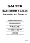
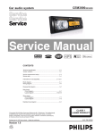
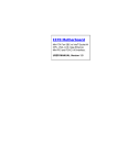
METHOD OF DISASSEMBLING CMB1100
ϔǃ7KHSURFHGXUHRIGLVDVVHPEOLQJWKHXQLW
1) Press EJ button and take out panel, Use electrical screw bit to take out the A screw in top cover
2˅ Use tweezer to prize up top cover as blue arrow direction that below picture showed
3˅ Use electrical screw bit to take out B,C two screws in left and right side of metal bracket
4˅ Use electrical screw bit to take out D,E screws in panel base , uplift deck mechanism and take out
the FFC of deck mechanism
B
A
EJ䪂
EJ button
D
E
C
Ѡǃ7KHSURFHGXUHRIGLVDVVHPEOLQJWKHSDQHO
˅8VHHOHFWULFDOVFUHZELWWRWDNHRXWILYHVFUHZVLQEDFNSDQHO
˅6HSDUDWHEDFNSDQHODQGIURQWSDQHO
˅7DNHRXW.%ERDUG
7DNHRXWVFUHZVLQEDFNSDQHO
2
BLOCK DIAGRAM
3
WIRING DIAGRAM
4
CIRCUIT DIAGRAM -MAIN BOARD
5
6
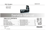
CIRCUIT DIAGRAM -PANEL BOARD
SYS_5V 17
R924
BT_LED 16
LAMP_VCC 15
INH 14
DATA 13
R925
DTH 10
NC
CLK 12
CE 11
S30
S31
S32
S12
S13
S14
S15
S16
13
14
15
16
S8
12
S7
S9
S6
8
S11
S5
7
11
S4
6
S10
S3
5
10
S2
4
9
S1
3
35
34
33
S34
S33
32
36
NC
S29
31
37
49
S35
S49
S36
22
22
50
30
S37
22
10UF
R930
R928
S50
S28
29
38
C908
R929
51
S27
28
S38
NC
104
S51
S26
NC
USB_5V 18
C911
22
52
39
C909
C910
R927
S52
42
USB_DP 21
USB_DN 20
USB
1
2
3
4
GND 22
USB901
CON901
53
S42
USB_GND
S53
43
104
S43
ZD904
6V8
27
44
2P
S25
26
S44
ZD903
6V8
S24
25
45
2P
54
VDD
S45
ZD902
6V8
S54
S23
24
46
2P
C905
S22
23
SC75823
INH
47
ZD901
6V8
C904
55
S21
21
22
48
2P
C903
S55
S20
20
IC901
VSS
S46
56
C902
OSC
58
57
C901
USB_5V 19
59
680P
S19
19
S47
C906
S[0:100]
LED917
BLUE
LED918 WHITE
LED919 BLUE
60
S18
18
CE
S39
61
S17
17
CLK
40
47K
R931
DO
S40
62
S48
270
R950
220
R949
270
R948
63
47k
41
64
R952
S41
Q901
9014C
1k
2
R951
1
S55
S54
S53
S50
S1
S2
S3
S4
S5
S16
S6
S7
S8
S9
S10
S1
S11
S12
S13
S14
S15
S16
S17
S18
S19
S20
S21
S22
S23
S24
S25
S30
S44
S26
S27
S28
S29
S30
S31
S32
S33
S34
S52
S35
S36
S37
S38
S39
S51
S48
S47
S40
S41
S42
S43
S55
S53
S54
S55
S6
S45
S11
S21
S46
S47
S48
S49
S51
1
2
3
4
5
6
7
8
9
10
11
12
13
14
15
16
17
18
19
20
21
22
23
24
25
26
27
28
29
30
31
32
33
34
35
36
37
38
39
40
41
42
43
44
45
46
47
48
49
50
51
52
53
54
55
56
57
58
59
60
61
62
63
64
65
66
67
68
270
270
R953
LCD-68
LED920 BLUE
270
R947
LED916 BLUE
270
R946
LED915 BLUE
270
R945
LED914 BLUE
270
R944
LED913 BLUE
270
R943
LED912 BLUE
270
R942
LED911 BLUE
270
R941
LED910 BLUE
270
R940
LED909 BLUE
270
R939
LED908 BLUE
270
R938
LED907 BLUE
270
R937
LED906 BLUE
270
R936
LED905 BLUE
270
R935
LED904 BLUE
270
R934
LED903 BLUE
270
R933
LED902 BLUE
LED901 BLUE
R932
LCD901
R901
R902
R903
R904
R905
R906
R907
R908
R909
R910
R911
180
220
330
470
680
1K
1K5
2K2
3K3
4K7
18K
SW901
M1/SONG
REMOTE 9
SW902
M2/FOLDER
SW903
SW905
SW904
M3/RPT
EQ/SOUND
MENU
SW906
SW907
SOURCE
DBB/AS
SW908
SW909
SW910
SW911
SW912
TUNE/SEEK-UP
TUNER/SEEK-DN
TRACK-DN
M4/SHUF
M5/INTRO
M6/PAU
TRACK-UP
ENCODER 8
+5V 7
GND 6
KEY2 5
KEY1 4
AUX_R 3
AUX_L 2
REM901
R923
47K
JACK-3P
C912
C913
22p
22p
AUX_GND
R914
R915
R916
R917
R918
R919
R920
R921
220
330
470
680
1K
1K5
2K2
3K3
4K7
SW913
SW914
DISP
SOUND
SW915
SW916
SW917
BAND
ESC
EJ
SW918
UP-ZONE
SW919
DN
R926
EN901
VOL
4
3
2
1
3
AUX901
2
1
82K
R913
180
1
2
3
R922
AUX_GND
5
GND 1
22-PIN
R912
10
ENC
C907
10UF
Power/MUTE/OK
M1
M2
M3
M4
MARK
1
MARK
1
MARK
1
MARK
1
7
CIRCUIT DIAGRAM -REMOTE BOARD
/('
3
3
/'
9
%$7
8)9
&
;7
0+]
&
,&
3
3
3
3
3
3
5(0
*1'
3
3
26&,
26&2
9''
3
&
3
3
92/
$
(4
92/
32:(5087(
'2:1
83
35(9
%
6285&(
1(;7
&
&
8
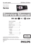
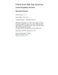
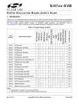
CIRCUIT DIAGRAM -TUNER BOARD
XT001
R014
100
32.768KHz
C008
220K
C018
Q004
4K7
9014S
16
14
VDD
13
VIO
15
GND
RCLK
ROUT
9
10
11
12
C016
FB152
C019
C025
1UF
C020
104
C011
103
L009
FB152
474
L007
220UH
C021
R010
1U
10
EC001
3
4
5
6
CN001
7
8
9
100
10
11
CLK
2
100
100
1
R012
R011
47UF
R013
12
DATA
104
RDS
C020
474
RES
10K
8
17
LOUT
L010
FB152
GND
R008
4K7
R009
AMI
18
DO
C112
+3V3
9018S
C015
104
RF-GND
L008
104
RFGND
10K
5
SI474X
DFS
103
L-OUT
Q002
CTUNE
R006
R007
R004
4
IC001
7
DGND
10M
AGC
104
R-OUT
C014 R005
122
3
C007
1MH
9014S
RFGND
333
RFGND
SCLK
C013
2
6
33UH
183
L005
Q102/Q003
FM ANT
FB152
L006
C017
19
SDIO
103
20
FMI
RST
C005
4K7
21
1
SEN
R002
AM
L004
2.7UH
22
DCLK
SK255
220NH
15P
47P
L003
23
INT
L002
24
GP01
47
30P
30P
C002
C006
R003
NC
220NH
Q001
NC
30P
C004
C003
NC
270K
L001
22P
22P
R001
C001
C009
TUNER23
9
PCB LAYOUT-MAIN BOARD TOP SIDE VIEW
10
PCB LAYOUT-MAIN BOARD BOTTOM SIDE VIEW
11
PCB LAYOUT-PANEL BOARD TOP SIDE VIEW
12
PCB LAYOUT-PANEL BOARD BOTTOM SIDE VIEW
13
PCB LAYOUT-REMOTE BOARD TOP SIDE VIEW
14
PCB LAYOUT-REMOTE BOARD BOTTOM SIDE VIEW
15
PCB LYOUT-TUNER BOARD TOP SIDE VIEW
16
PCB LYOUT-TUNER BOARD BOTTOM SIDE VIEW
17
PCB LAYOUT-ISO BOARD BOTTOM SIDE VIEW
18
PCB LAYOUT-CD CONNECTOR BOARD TOP SIDE VIEW
19
SET EXPLODER VIEW DRAWING
CMB1100
Trouble shooting
Product Model
failure
NO.
1
2
NO Power
NO audio
output
Date
$OO$UHD
failure cause
a. To check whether it is connect well of the ISO connector (4PIN power input ). Whether it is loose of
the 15A fuse of the ISO connector, or insert non in place.
b. To check whether the reset button Sw201 is long term functional then caused short circuit and no
power.
c. To check whether there is any contamination and bad contact on the 22 Pin male/female connector
on the panel and main board.
d. To check the power supply of main board B+ǃACC should be +12V; The voltage of stabilivolt of
ACC power supply circuit ZD210 (6V8) should be 6V8.
e. To check the voltage of the 19 pin (AVDD) of MCU (T5CL8) should be +3V3; The output voltage of
IC307 (LM2950) should be +3V3.
f. To check the oscillation frequence of crystal X201 , shuold be 8MHz, and for the crystal X202 should
be 32.768KHZ.
g. To check Panel LED +5V voltage , should be normal.
a. To check whether the volume knob is turn to the minimum position.
b. To check whether the unit is at MUTE mode, press SOURCE button and check whether it is effective
of the input sound source.
c. To check whether the connection of 8PIN audio output wire of ISO connector is correct; wrong
connection or short circuit to the ground will caused the protection of the power amplifier( no voltage
output).
CMB1100
Area
2011-11-15
remark
d . To check the circuit of power amplifier IC501 (LV47004) and VOL IC403 (PT7313E).
e. To check the normal voltage of 22 PIN(MUTE) of power amplifier IC501(LV47004) , normally should
be 4V.
f. To check the voltage of control PIN SDAǃSCL˄the 27ǃ28pin˅of audio processor IC402
˄PT7313E˅, should be +3V3.
a. To check the antenna of the tuner.
b. To check whether the strength of then input signal of the tuner is too weak.
c. To check the voltage of the 7 pin(VDD) of the tuner , should be +3V3.
3
5DGLRDEQRUPDO
d. To check the voltage of the 10 pin(RES) of the tuner, should be +3V6; the 11 pin(CLK) should be
+3V1; the 12 pin(date) should be +2V8.
e. To check the oscillation frequence of crystal XT001 of the tuner, should be 32.768KHZ.
f. To check the L output voltage of the 5 pin of tuner should be 1V5, the 6 pin R output voltage , should
be 1V5.
21
NO.
failure phenomena
failure cause
remark
a. To check whether the signal format of the disc is correspond to the request of the unit, whether
there is any contamination or damage or light leakage on the surface of the disc.
b. To check whether there is any abnormal of the rotation of the deck mecahnism, or whether the
disc is enter in position.
c. To check whether it is normal when reading USB?
d. To check whether the 17 P FFC of laser pick up is inserted in place, whether the socket of it is
loose.
e. To check whether there is any contamination or foreign body on the surface of the laser pick up.
4
&'GHIHFWLYH
f. To check the servo connector of CON601ǃCON602.
g. To check the oscillation frequence of crystal X602 , should be 16.9344M.
h. To check the oscillation frequence of crystal X603 , should be 9MHZ.
i. To check the voltage of the 50 pin of IC 602, should be 3.3V.
j. To check the switch S601 on the servo board.
k. To check the rotation mechanism of CD deck mechanism.
l. To check the voltage of the 8 pin of IC 603, should be +8V.
m. To check whether the rotation belt of deck mechanism is dislocation or loose.
a. To check the SOURCE shoule be in MP3-LINK mode.
b. To check the AUX IN input signal.
5
AUX defective
c. To check whether there is any contamination and bad contact on the male/female connector of
the panel and main board. If necessary, can exchange the panel to test whether the defective is
occurred by the unit or panel.
22