1
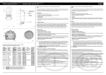
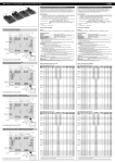
2(0 User manual We want you to save time and money! We assure you that the thorough reading of this manual will guarantee proper installation and safe use of the described product. IMPORTANT WARNINGS BEFORE INSTALLING OR HANDLING THE APPLIANCE, PLEASE CAREFULLY READ AND FOLLOW THE INSTRUCTIONS AND SAFETY REGULATIONS CONTAINED IN THIS MANUAL AND INDICATED ON THE LABELS ATTACHED TO THE MACHINE. INSTRUCTION SHEET +050003755 OF THE CP* CONTROL BOARD IS AN INTEGRAL PART OF THIS MANUAL! CAREFULLY KEEP INSTRUCTION SHEET +050003755 TOGETHER WITH THIS MANUAL! This humidifier produces non-pressurised steam by means of electrodes immersed in the water contained in the cylinder-boiler (hereafter referred to as the cylinder). The electrodes pass electric current through water, which, acting as electrical resistance, superheats. The produced steam is used to humidify rooms or industrial processes, by means of special distributors. As the quality of the water in use affects the evaporation process, the appliance may be supplied with untreated water as long as it is drinkable and not demineralised (refer to supply water requirements); the evaporated water is automatically replaced by means of a fill valve. This appliance has been designed exclusively to humidify rooms directly or in ducts through a distribution system. Installation, use and maintenance shall be carried out according to the instructions contained in this manual. The environmental conditions and the power supply voltage must comply with the specified values. Any other use and modification to the appliance not expressly authorised by the manufacturer shall be considered as improper. Liability for injuries or damage caused by improper use lies exclusively with the user. Please note that the machine contains live electrical devices and hot surfaces. All service and/or maintenance operations must be carried out by specialist and qualified personnel aware of the necessary precautions and able to operate properly. Disconnect the machine from the mains before accessing any internal parts. The appliance must be installed in compliance with the local regulations in force. The local safety regulations in force must be applied in all cases. Disposal of humidifier parts The humidifier consists of metal and plastic components; all parts must be disposed of in compliance with the local regulations concerning waste disposal. Materials warranty: 2 years (from the date of production, consumable parts excluded – e.g. the cylinder). Certification: the quality and safety of Carel’s products are guaranteed by the ISO 9001 certified design and production system, as well as by the mark. CONTENTS 1. MODELS AND DESCRIPTION OF THE COMPONENTS ....................................................................................................................... 9 1.1 Description of the components............................................................................................................................................................. 9 2. INSTALLATION: dimensions, weights and pipes connection................................................................................................................... 12 2.1 Positioning.......................................................................................................................................................................................... 12 2.2 Pipes connection................................................................................................................................................................................. 13 2.3 Drain................................................................................................................................................................................................... 13 2.4 Supply ................................................................................................................................................................................................ 14 2.5 Checks ................................................................................................................................................................................................ 14 2.6 Installation of the steam pipe and the condensate return pipe............................................................................................................. 14 2.7 Water requirements ............................................................................................................................................................................ 15 2.7.1 Supply water....................................................................................................................................................................................... 15 2.8 Drain water......................................................................................................................................................................................... 16 3. ELECTRICAL CONNECTIONS (with Carel CP control)........................................................................................................................ 17 3.1 Single-phase wiring diagram – EXTERNAL TAM (CP1) ................................................................................................................. 17 3.2 Single-phase wiring diagram – INTERNAL TAM (CP2) .................................................................................................................. 18 3.3 Single-phase wiring diagram – INT. TAM with remote control switch (CP4)................................................................................... 19 3.4 Single-phase wiring diagram – EXT. TAM with remote control switch (CP3).................................................................................. 20 3.5 Three-phase wiring diagram – EXTERNAL TAM (CP3).................................................................................................................. 21 3.6 Three-phase wiring diagram – INTERNAL TAM (CP4)................................................................................................................... 22 4. START-UP, CONTROL AND SHUT-DOWN ............................................................................................................................................ 23 4.1 Preliminary checks ............................................................................................................................................................................. 23 4.2 Start-up............................................................................................................................................................................................... 23 4.2.1 Start-up with empty cylinder .............................................................................................................................................................. 23 5. MAINTENANCE AND SPARE PARTS ..................................................................................................................................................... 24 5.1 Replacing the cylinder........................................................................................................................................................................ 24 5.2 Maintenance of the other hydraulic components ................................................................................................................................ 25 5.3 Replacing the components.................................................................................................................................................................. 26 5.3.1 Fuses of the auxiliary circuits............................................................................................................................................................. 26 5.4 Spare parts.......................................................................................................................................................................................... 26 5.4.1 SINGLE-PHASE humidifiers: ........................................................................................................................................................... 26 Standard spare parts ......................................................................................................................................................................... 26 Spare parts for special applications .................................................................................................................................................. 26 5.4.2 THREE-PHASE humidifiers:............................................................................................................................................................. 27 Standard spare parts ......................................................................................................................................................................... 27 Spare parts for special applications .................................................................................................................................................. 27 5.5 Troubleshooting table......................................................................................................................................................................... 28 5.6 Alarms ................................................................................................................................................................................................ 28 6. OPERATING PRINCIPLES, CONTROL AND OTHER FUNCTIONS ................................................................................................. 29 6.1 Operating principle............................................................................................................................................................................. 29 6.2 Control principles............................................................................................................................................................................... 29 6.2.1 ON/OFF control ................................................................................................................................................................................. 29 6.2.2 Proportional control............................................................................................................................................................................ 29 7. TECHNICAL SPECIFICATIONS............................................................................................................................................................... 30 OEM 1. MODELS AND DESCRIPTION OF THE COMPONENTS The code that identifies the humidifier model is made up of 10 characters having the following meaning: K U E * * * ** * * Revision level Family prefix Type of power supply 0= without cylinder S= single-phase T= three-phase Size and steam production R=1.5/3 Kg/h compact 1= 1.5/3 Kg/h 2= 5/8 Kg/h 3= 10/15 Kg/h Cylinder conductivity range A B C D E (1~) F (1~) 0 = w/o cylinder Customisation ØØ= standard vers. – single package MP= standard vers. – multiple package Type of cylinder Ø = disposable or w/o cylinder C = cleanable Example: - KUET3D00C0 = UE OEM KIT with 15 Kg/h steam cleanable three-phase cylinder for standard conductivity, CAREL at revision level 0; - KUE010MP00 = UE OEM KIT 1.5/3 Kg/h steam - compact - w/o cylinder, with multiple package at revision level 0. 1.1 Description of the components no. 1 2 3 4 4a 5 6 description Bearing frame Cylinder Drain solenoid valve 90° revolving drain connection Straight drain connection (supplied) Fill tank + conductivity meter Fill solenoid valve Tab. 1.1.1 Fig. 1.1.1 Cod. +030221791 - Rel. 1.0 - 18/10/02 9 OEM CP* control boards (also refer to instruction sheet +050003755 of the boards) Fig. 1.1.1a. Key: CP1: controller for KUE single-phase (KUE*S*) with external TAM CP2: controller for KUE single-phase (KUE*S*) with built-in TAM CP3: controller for KUE single/three-phase with external TAM CP4: controller for KUE single/three-phase with built-in TAM Cod. +030221791 - Rel. 1.0 - 18/10/02 10 OEM Fig. 1.1.1b. External TAM (required for CP1* and CP3* boards only) For the description of Fig. 1.2.2, refer to the following table. no. 1 2 3 4 5 6 7 8 9 10 11 12 13 description Fill solenoid valve Flow rate limiting device Supply pipe Fill pipe Overflow pipe Conductivity measuring electrodes Fill tank – overflow device * High level electrodes Steam outlet Electrodes (2/6 in single-phase model, 3/6 in three-phase model) Cylinder casing Bottom filter Drain solenoid valve Tab. 1.2.1 * Device used to prevent water overflowing from the fill tank above the safety level (e.g., due to a controller malfunction, fill solenoid valve overflowing or back pressures). The fill tank is equipped with an overflow diaphragm that discharges the excess water through a special pipe. The overflow diaphragm is located in a lower position with respect to the fill one (-40mm) in order to prevent back-flow into the fill pipe. Cod. +030221791 - Rel. 1.0 - 18/10/02 11 Fig. 1.2.2 OEM 2. INSTALLATION: dimensions, weights and pipes connection 2.1 Positioning • • • To favour steam distribution, position the appliance so as to minimise the length of the steam supply pipe (max 4 mt). The unit has been designed for wall mounting; the wall must be able to support the weight of the uit during mnachine operation. The cylinder of the humidifier may reach temperatures above ≥ 60 °C. Make sure that the humidifier is level. Raccordo di alimentazione 3/4 “ Gas maschio Raccordo di drenaggio diam. 32 mm N. 4 fori di fissaggio 6x10 Cod. +030221791 - Rel. 1.0 - 18/10/02 Supply connection 3/4 “ Gas male Drain connection dia. 32mm No. 4 fastening holes 6x10 12 OEM Sizes and Weights Models Weights ( Kg ) Dimensions (mm) Pipes connection (mm) Distances (mm) Empty Packed Installed H L P ØV ØS V1 V2 V3 V4 V5 S1 S2 S3 S4a-S4b S5a-S5b-S5c A1 A2 X X1 Y Y1 KUESR* 1.2 2.0 3.7 300 160 170 23-30 32 81,5 78,5 99,5 54 16-17 46 114 98 40-50 13-15-30 19.5 53 36 90 146 68 KUE*1* 1.6 2.4 5.5 391 160 170 23-30 32 81,5 78,5 99,5 54 16-17 46 114 98 40-50 13-15-30 19.5 53 36 90 146 68 KUE*2* 2.9 3.7 8.9 412 185 220 30 32 93 92 124 20 37 54 131 118 40-50 13-15-30 19.5 53 47 90 213 68 KUE*3* 3.5 4.3 13.8 512 225 230 30 32 112.5 112.5 135 26 37 77 148 118 40-50 13-15-30 19.5 53 74 99 316 75 The appliance can be either wall-mounted by using the appropriate fastening holes or installed on bracket so that the hydraulic connections can be executed. 2.2 Pipes connection The installation of the humidifier requires connection to the water supply and drain pipes. cock drain water supply filter drain trap 2.3 Drain Models Max. drain instant flow rate l/min Drain water connection (mm) Drain pipe min. inside Ø KUESR* ~4 32 25 KUE*1* ~4 32 25 KUE*2* ~4 32 25 KUE*3* ~4 32 25 The drain water connection is made using a section of rubber or plastic tubing resistant to 100 °C, with 32 mm suggested inside diameter (compliant with DIN 19535, UNI 8451/8452). The drain union is suitable for heat seal with polypropylene drain pipes. IMPORTANT WARNING: the drain pipe must be free, without back pressure and must be equipped with a drain trap downstream of the connection to the humidifier. Cod. +030221791 - Rel. 1.0 - 18/10/02 13 OEM 2.4 Supply Models Max. supply instant flow rate l/min Supply water connection Supply pipe min. inside Ø (rigid or flexible pipe) KUE*R* 0.6 ¾ ”G male KUE*1* 0.6 ¾ ”G male KUE*2* 0.6 ¾ ”G male KUE*3* 1.2 ¾ ”G male 6 6 6 6 Tab. 2.4.1 To facilitate installation, use Carel’s flexible pipe code FWH3415000 (¾”G straight + flexible pipe in PVC fitted with flexible stiffening + ¾”G 90°; max 20 bar, max 1,5m) or flexible pipe with 6mm inside diameter and 8mm outside diameter (code 1312350APN can be ordered per meter) and the ¾” G revolving union, either straight (code 9995727ACA) or with 90° elbow (code 9995728ACA), both available on request. A cut-off cock and a mechanical filter should be installed to trap any solid impurities. 2.5 Checks Proper hydraulic connection is obtained when the following conditions are met: • • • • • • • • installation of a cut-off cock in the supply water line; presence of a mechanical filter in the supply water line; water temperature and pressure within the allowed values; drain pipe resistant to 100 °C; drain pipe minimum inside diameter corresponding to 25 mm; drain pipe minimum slope higher than or equal to 5°; non-conductive sleeve; presence of a drain trap inside the drain pipe. IMPORTANT WARNING: upon installation completion, drain the supply pipe for approximately 30 minutes by piping the water directly into the drain connection without sending it to the humidifier. This operation allows eliminating any possible residual product that could clog the fill valve and/or produce foam during boiling. 2.6 Installation of the steam pipe and the condensate return pipe The humidifier must be connected to the distributor by using a pipe suitable for this purpose, such as Carel’s flexible pipe. Make sure that pockets or traps are not forming, as condensate might be trapped into them. Make sure that the pipe is not choked due to sharp bends or twisting. Use screw clamps to fasten the ends of the pipe. IMPORTANT WARNING: before starting the unit, remove the PE film wrapping the pipe to allow proper heat exchange. Cod. +030221791 - Rel. 1.0 - 18/10/02 14 OEM The pipe may run according to either of the two following solutions: Steam pipe Steam condensate pipe IMPORTANT WARNING: the length of the steam pipe should not exceed 4 m. To allow the drain trap of the steam condensate pipe to operate properly, it must be filled with water prior to humidifier start-up. 2.7 Water requirements 2.7.1 Supply water The humidifier must be supplied with aqueduct water having the following requirements: pressure between 0.1 and 0.8 MPa (1-8 bar, 14.5-116 PSI); temperature between 1 and 40 °C; instant flow rate not lower than the fill solenoid valve rated flow rate (refer to table 2.4.1); connection type ¾”G male. LIMIT VALUES FOR MEDIUM-HIGH CONDUCTIVITY SUPPLY WATER OF A HUMIDIFIER WITH IMMERSED ELECTRODES LIMITS Min Max Hydrogen ions pH Specific conductivity at 20 °C µS/cm σR, 20 °C Total dissolved solids TDS mg/l Dry residue at 180 °C R180 mg/l Total hardness TH - mg/l CaCO3 Temporary hardness - mg/l CaCO3 Iron + Manganese - mg/l Fe + Mn Chlorides ppm Cl Silica mg/l SiO2 Residual chlorine mg/l ClCalcium sulphate - mg/l CaSO4 Metallic impurities mg/l Solvents, diluents, soaps, lubricants mg/l 1 ( ) Values depending on specific conductivity; in general: TDS ≅ 0.93 * σ20; R180 ≅ 0.65 * σ20 (2) not lower than 200% of chlorides content in mg/l of Cl(3) not lower than 300% of chlorides content in mg/l of Cl- 7 8.5 300 1250 (1) (1) 1 () (1) 2 100( ) 400 60(3) 300 0 0.2 0 30 0 20 0 0.2 0 100 0 0 0 0 Tab. 3.1.1 Cod. +030221791 - Rel. 1.0 - 18/10/02 15 OEM LIMIT VALUES FOR MEDIUM-LOW CONDUCTIVITY HUMIDIFIER WITH IMMERSED ELECTRODES Hydrogen ions Specific conductivity at 20 °C Total dissolved solids Dry residue at 180 °C Total hardness Temporary hardness Iron + Manganese Chlorides Silica Residual chlorine Calcium sulphate Metallic impurities Solvents, diluents, soaps, lubricants SUPPLY WATER pH σR, 20 °C TDS R180 TH OF A µS/cm mg/l mg/l - mg/l CaCO3 - mg/l CaCO3 - mg/l Fe + Mn ppm Cl mg/l SiO2 mg/l Cl- mg/l CaSO4 mg/l mg/l (1) Values depending on specific conductivity; in general: TDS ≅ 0.93 * σ20; R180 ≅ 0.65 * σ20 (2) not lower than 200% of chlorides content in mg/l of Cl(3) not lower than 300% of chlorides content in mg/l of ClWarning: no relation can be demonstrated between water hardness and conductivity. LIMITS Min Max 7 8.5 125 500 (1) (1) 1 () (1) 2 50( ) 250 30(3) 150 0 0.2 0 20 0 20 0 0.2 0 60 0 0 0 0 Tab. 3.1.2 IMPORTANT WARNING: do not treat water with softeners! This could cause corrosion of the electrodes or the formation of foam, leading to potential operative problems or failures. Avoid: 1. using well water, industrial water or water drawn from cooling circuits; in general, avoid using potentially contaminated water, either from a chemical or bacteriological point of view; 2. adding disinfectants or corrosion inhibiters to water, as these substances are potentially irritant. 2.8 Drain water Inside the humidifier, water boils and turns into steam without the addition of any type of substance. As a result, the drain water contains the same substances that are dissolved in the supply water, yet in greater quantity, as a function of the concentration in the supply water and of the set drain cycles. The drain water can reach 100 °C and ~4 l/min instant flow rate. As the drain water is not toxic, it can be drained into the white waters system. The drain connection has 32 mm outside diameter. Cod. +030221791 - Rel. 1.0 - 18/10/02 16 OEM 3. ELECTRICAL CONNECTIONS (with Carel CP control) Before executing the connections, make sure that the machine is disconnected from the mains. For further information concerning control, refer to the data sheet cod. +050003755. WARNING: the following signal cables must be shielded and laid apart from power cables as by EMC norms: - external regulator - remote on/off - external TAM (CP1 and CP3 only) - high level sensor - conductibility sensor 3.1 Single-phase wiring diagram – EXTERNAL TAM (CP1) (*) material not supplied by Carel (**) no. of turns through TAM: refer to data sheet code +050003755 Cod. +030221791 - Rel. 1.0 - 18/10/02 17 OEM 3.2 Single-phase wiring diagram – INTERNAL TAM (CP2) (*) material not supplied by Carel (**) no. of turns through TAM: refer to data sheet code +050003755 Cod. +030221791 - Rel. 1.0 - 18/10/02 18 OEM 3.3 Single-phase wiring diagram – INT. TAM with remote control switch (CP4) (*) material not supplied by Carel (**) no. of turns through TAM: refer to data sheet code +050003755 Cod. +030221791 - Rel. 1.0 - 18/10/02 19 OEM 3.4 Single-phase wiring diagram – EXT. TAM with remote control switch (CP3) (*) material not supplied by Carel (**) no. of turns through TAM: refer to data sheet code +050003755 Cod. +030221791 - Rel. 1.0 - 18/10/02 20 OEM 3.5 Three-phase wiring diagram – EXTERNAL TAM (CP3) (*) material not supplied by Carel (**) no. of turns through TAM: refer to data sheet code +050003755 Cod. +030221791 - Rel. 1.0 - 18/10/02 21 OEM 3.6 Three-phase wiring diagram – INTERNAL TAM (CP4) (*) material not supplied by Carel (**) no. of turns through TAM: refer to data sheet code +050003755 Cod. +030221791 - Rel. 1.0 - 18/10/02 22 OEM 4. START-UP, CONTROL AND SHUT-DOWN IMPORTANT WARNINGS: 1. Prior to machine start-up, check that the humidifier is in good condition, that no water leak is present and that the electrical parts are dry. 2. Do not power the appliance in case it is damaged or even partially wet! Upon installation completion, drain the fill pipe for approximately 30 minutes by piping the water directly into the drain connection without sending it to the humidifier. This operation allows eliminating any possible residual product that could clog the drain valve and produce foam during boiling. 4.1 Preliminary checks Before starting the humidifier, check that: • the hydraulic and electrical connections and the steam distribution system have been executed according to the instructions contained in this manual; • the water cut-off cock to the humidifier is open; • the line fuses are installed and intact; • the AB terminals of the CP control board are provided with jumper or connected to the ON/OFF remote contact; also check that the ON/OFF contact is closed; • the steam outflow pipe is not choked. 4.2 Start-up 4.2.1 Start-up with empty cylinder This phase will take place automatically when the machine is started: the rated production will be obtained after a certain period has passed (such interval depends considerably on the conductivity of the supply water and may last for some hours). Cod. +030221791 - Rel. 1.0 - 18/10/02 23 OEM 5. MAINTENANCE AND SPARE PARTS 5.1 Replacing the cylinder IMPORTANT WARNING: the cylinder might be hot: before touching it, let it cool or use protective gloves. To intervene on the cylinder: • completely drain the water contained in the cylinder; • turn the appliance off and open the mains knife switch (safety procedure); • remove the steam pipe from the cylinder; • disconnect the electrical connections from the top of the cylinder; • release the cylinder from the fasteners and lift it for removal; • assemble the new cylinder on the humidifier operating in reverse order. Maintenance of the cylinder (refer to cylinders instruction sheet) The duration of the cylinder depends on different factors, including: complete filling with limestone and/or partial or total corrosion of the electrodes, proper use and dimensioning of the humidifier, working output, water quality, careful and regular maintenance. Due to plastics ageing and electrodes wear, even an openable steam cylinder has a limited duration in time; therefore, it is suggested to replace the cylinder after 5 years or 10,000 working hours. Important warnings The humidifier and the cylinder contain live electrical devices and hot surfaces, therefore all service and/or maintenance operations must be carried out by specialist and qualified personnel aware of the necessary precautions. Before intervening on the cylinder, make sure that the humidifier is disconnected from the mains; carefully read and follow the instructions contained in this manual. Remove the cylinder from the humidifier only after it has been drained completely. Make sure that the model and power supply voltage of the new cylinder correspond to the data of the replaced cylinder. Periodical checks • After one hour of operation For both the disposable and openable cylinders, check that no significant water leak is present. • Every fortnight and no more than 300 working hours For both the disposable and openable cylinders, check that no significant water leak is present and verify cylinder operation and the general conditions of the container. Also check that no arc or spark originate between the electrodes when the machine is operating. • Every three months and no more than 1,000 working hours For disposable cylinders, verify cylinder operation, check that no significant water leak is present and replace the cylinder, if required. For openable cylinders, check the container for markedly blackened areas: in case they are present, check the scale condition of the electrodes and, if necessary, replace them together with the O-rings and the cover gasket. • Every year and no more than 2,500 working hours For disposable cylinders, replace the cylinder. For openable cylinders, check that no significant water leak is present, verify cylinder operation and the general conditions of the container. Also check the container for markedly blackened areas: in case they are present, replace the electrodes together with the O-rings and the cover gasket. • After 5 years and no more than 10,000 working hours For both the disposable and openable cylinders, replace the cylinder. After extended use or due to the use of water with a high salt content, the solid deposits that form naturally on the electrodes might spread until they cover the cylinder internal wall. In case particularly conductive deposits form, the heat consequently produced might overheat plastic and melt it; in the most severe cases, heat might perforate plastic, causing the water to leak from the cylinder to the tank. As a precaution, check the quantity of deposits and verify that no deformation or blackening is present on the wall of the cylinder, otherwise replace it. WARNING: in case of leak, disconnect the appliance before touching the cylinder, as current might be present in water. Cod. +030221791 - Rel. 1.0 - 18/10/02 24 OEM 5.2 Maintenance of the other hydraulic components IMPORTANT WARNINGS: • Do not use detergents or solvents for plastic components cleaning. • Scale can be removed using a solution with 20% vinegar or acetic acid and then rinsing with water. The only steam humidifier component that requires periodical replacement is the steam production cylinder. Replacement is required when the limestone deposits that form inside the cylinder prevent current from flowing properly. In this case, an alarm signal is displayed on the controller. The frequency of this operation depends on the supply water: the more water contains salts or impurities, the more cylinder replacement will be frequent. no. 1 2 3 4 5 6 7 8 9 10 11 12 description Bearing frame Cylinder lock belt Fill tank + conductivity meter Overflow pipe Cylinder fill pipe Tank fill pipe Fill solenoid valve Fill/drain manifold Gasket 90° elbow drain union Straight drain union (supplied) Drain solenoid valve Tab. 5.2.1 • Fill solenoid valve (Fig. 5.2.1, part no. 7) After disconnecting cables and pipes, remove the solenoid valve and check cleaning of the inlet filter; if required, clean it using water and a soft brush. • Fill and drain manifold (Fig. 5.2.1, part no. 8) Check that no solid deposit is present inside the cylinder seat; remove impurities, if any. Check that the O-ring is not damaged or cracked; replace it if necessary. • Drain solenoid valve (Fig. 5.2.1, part no. 12) Cut power off, remove the coil and disassemble the valve body after having unscrewed the two screws fastening it to the manifold; remove impurities, if any, and rinse. • Fill tank + conductivity meter (Fig. 5.2.1, part no. 3) Verify that no clog or solid particle is present and check the conductivity measuring electrodes for proper cleaning; remove impurities, if any, and rinse. • Supply, fill and overflow pipes (Fig. 5.2.1, parts no. 4, 5, 6) Check the pipes for proper clearing and cleaning; remove impurities, if any, and rinse. IMPORTANT WARNING: after replacing or checking the hydraulic parts, verify the connections for proper execution. Start the machine again and carry out some fill and drain cycles (from 2 to 4); upon cycles completion, check for water leaks, if any, in compliance with the safety procedure. Fig. 5.2.1 Cod. +030221791 - Rel. 1.0 - 18/10/02 25 OEM 5.3 Replacing the components 5.3.1 Fuses of the auxiliary circuits Use fuses with the ratings indicated in tab. 5.3.1. MODELS fuses 1- 2 fuse 3 *** ***: on the CP control board only. 5.4 KUES1* or KUESR* KUET1* KUET2* KUET3* 1 A, GL, 10.3 x 38 contained in the fuse carriers on Omega rail 2 A, T, 5x20 Tab. 5.3.1 Spare parts 5.4.1 SINGLE-PHASE humidifiers: Standard spare parts Model Hydraulic part Cylinder lock belt (must be cut accordingly along the lines of pre-fracture) Fill tank + conductivity meter Fill solenoid valve kit Drain solenoid valve kit Drain unions kit Internal pipes kit * *: pipes must be cut at the required size before installation Non-openable cylinders 200-230 VAC 1~, conductivity 300-1250 µS/cm Electronic part Control board ver. CP KUESR* KUES1* 18C499A006 13C119A003 KITVC00006 13C476A050 KITRAC0000 UEKT00000S 18C499A006 13C119A003 KITVC00006 13C476A050 KITRAC0000 UEKT00000S BL0SRF00H0 BL0S1F00H1 refer to data sheet code +050003755 Tab. 5.4.1.1 Spare parts for special applications The following spare parts are supplied separately from the standard humidifier, therefore they must be ordered separately. Model Non-openable cylinders 200-230 VAC 1~, conductivity 125-300 µS/cm KUESR* KUES1* BL0SRE00H0 BL0S1E00H1 Tab. 5.4.2.1 Cod. +030221791 - Rel. 1.0 - 18/10/02 26 OEM 5.4.2 THREE-PHASE humidifiers: Standard spare parts MODEL KUET1* Hydraulic part Cylinder lock belt 18C499A006 (must be cut accordingly along the lines of pre-fracture) Fill tank + conductivity meter 13C119A003 Fill solenoid valve kit KITVC00006 Drain solenoid valve kit 13C476A050 Drain unions kit KITRAC0000 Internal pipes kit * UEKT00000S *: pipes must be cut at the required size before installation Non-openable cylinders 200-230 VAC 3~, conductivity 350-1250 µS/cm 400 VAC 3~, conductivity 350÷750 µS/cm 460 VAC 3~, conductivity 350÷1250µS/cm 575VAC 3~, conductivity 350÷1250 µS/cm KUET2* KUET3* 18C499A006 18C499A006 13C119A003 KITVC00006 13C476A050 KITRAC0000 UEKT00000M 13C119A003 KITVC00012 13C476A050 KITRAC0000 UEKT00000M BL0T2B00H0 BL0T3B00H0 BL0T2C00H0 BL0T2D00H0 BL0T2D00H0 BL0T3C00H0 BL0T3D00H0 BL0T3D00H0 BL0T1D00H1 BL0T1D00H1 Electronic part Control board ver. CP refer to data sheet code +050003755 Tab. 5.4.3.1 Spare parts for special applications The following spare parts are supplied separately from the standard humidifier, therefore they must be ordered separately. MODEL Non-openable cylinders 200÷230 VAC 3~, conductivity 125÷350 µS/cm 400 VAC 3~, conductivity 125÷350 µS/cm 400 VAC 3~, conductivity 750÷1250 µS/cm 460 VAC 3~, conductivity 125÷350 µS/cm 575 VAC 3~, conductivity 125÷350 µS/cm KUET1* KUET2* KUET3* BL0T1A00H1 BL0T1A00H1 BL0T1D00H1 BL0T1B00H1 BL0T2A00H0 BL0T2B00H0 BL0T2D00H0 BL0T2C00H0 BL0T2C00H0 BL0T3A00H0 BL0T3B00H0 BL0T3D00H0 BL0T3C00H0 BL0T3C00H0 BLCT2A00W0 BLCT2B00W0 BLCT2B00W0 BLCT2C00W0 BLCT2D00W0 BLCT2C00W0 BLCT2D00W0 KITBLCT2A0 KITBLCT2B0 KITBLCT2B0 KITBLCT2C0 KITBLCT2D0 KITBLCT2C0 KITBLCT2D0 KITBLC2FG0 BLCT3A00W0 BLCT3B00W0 BLCT3B00W0 BLCT3C00W0 BLCT3D00W0 BLCT3C00W0 BLCT3D00W0 KITBLCT3A0 KITBLCT3B0 KITBLCT3B0 KITBLCT3C0 KITBLCT3D0 KITBLCT3C0 KITBLCT3D0 KITBLC3FG0 Openable cylinders 200÷230 VAC 3~, conductivity 125÷350 µS/cm 200÷230 VAC 3~, conductivity 350÷1250 µS/cm 400 VAC 3~, conductivity 125÷350 µS/cm 400 VAC 3~, conductivity 350÷750 µS/cm 400 VAC 3~, conductivity 750÷1250 µS/cm 460/575 VAC 3~, conductivity 125÷350 µS/cm 460/575 VAC 3~, conductivity 350÷1250 µS/cm Electrodes kit (200÷230 VAC 3~, 125÷350 µS/cm) Electrodes kit (200÷230 VAC 3~, 350÷1250 µS/cm) Electrodes kit (400 VAC 3~, 125÷350 µS/cm) Electrodes kit (400 VAC 3~, 350÷750 µS/cm) Electrodes kit (400 VAC 3~, 750÷1250 µS/cm) Electrodes kit (460/575 VAC 3~, 125÷350 µS/cm) Electrodes kit (460/575 VAC 3~, 350÷1250 µS/cm) Electrodes gaskets kit Tab. 5.4.4.1 Cod. +030221791 - Rel. 1.0 - 18/10/02 27 OEM 5.5 Troubleshooting table PROBLEM CAUSES SOLUTIONS 1. check protection device upstream of the humidifier and verify that power supply voltage is present; 2. controller connectors inserted improperly; 2. check connectors for proper insertion in the terminal The humidifier does not board; switch on 3. fuses disconnected; 3. check condition of fuses F1/F2/F3; 4. transformer faulty 4. check that voltage across the transformer secondary winding corresponds to 24 VAC 1. remote ON/OFF contact open (AB – AB terminals) 1. close ON/OFF contacts (AB – AB terminals) on CP on CP control board control board The humidifier does not start 2. control signal not compatible with the set type 2. check that the external signal is 0-10V 1. too high steam delivery back pressures; 1. check that the steam delivery pipe is not bent or choked; 2. cylinder inlet filter clogged; The humidifier loads with 3. limestone inside the supply tank; 2. clean the filter; water but does not produce 4. drain solenoid valve faulty 3. clean the supply tank; steam 4. check 24 Vac anomalous presence on the drain solenoid valve and/or replacement of drain solenoid valve 1. line magneto-thermal switch under-rated 1. check that the magneto-thermal switch has been rated for a current value corresponding to at least 1.5 times The line magneto-thermal the rated current of the humidifier switch enables 2. overcurrent to the electrodes 2. check the operation of the drain solenoid valve, the seal of the fill solenoid valve when it is not excited, drain part of the water and start the system again 1. distributor installed improperly (too close to the 1. check the steam distributor for proper installation; duct top) or condensate return is hindered; 1. no electric power; The humidifier wets the duct The humidifier wets the underlying floor 2. system over-rated; 2. decrease steam production set on the control board; 3. humidifier enabled but duct fan off 3. check connection of a device (flow switch or differential pressure switch) slaving the humidifier to the ventilation inside the duct (AB – AB terminals) of the CP control board 1. supply or overflow hydraulic circuit leaking; 2. steam delivery pipe not properly fastened to the cylinder 1. check the entire hydraulic circuit; 2. check fastening of the clamp on the steam delivery pipe Tab. 5.5 5.6 Alarms Refer to data sheet +050003755, which is an integral part of this manual. Cod. +030221791 - Rel. 1.0 - 18/10/02 28 OEM 6. OPERATING PRINCIPLES, CONTROL AND OTHER FUNCTIONS 6.1 Operating principle In a humidifier with electrodes, humidity is produced inside a cylinder (boiler) containing water that is heated to and then held at boiling temperature. The evaporated water is automatically replaced with water drawn from the supply network. The heat required for water boiling is obtained by passing electric current through the cylinder water; this operation can be executed by connecting the electrodes immersed inside the boiler to the electric supply network. The initial quantity of the flowing current strongly depends on the type of water coming from the supply network. Normally, a recently-started cylinder has low current. With the passing of time, the quantity of the salts contained in the water increases (as a matter of fact, evaporation does not include salts); this feature allows reaching the required current level so that the machine can provide for the required steam quantity. Under stable operating conditions, the required production level is automatically obtained by controlling the boiler water level. This control allows having higher or lower current levels. Part of the salts introduced in the water by the automatic refill settles inside the boiler as limestone, contributing to the progressive wear of the cylinder; the remaining salts keep dissolved in the water. In order to prevent excessive salt deposits, some water is periodically and automatically drained and then replaced with renewal water. 6.2 Control principles The range of humidifiers includes the following control options. 6.2.1 ON/OFF control Control is of on-off type and is enabled by an external contact that determines the control set-point and differential. 6.2.2 Proportional control The steam production (quantity per hour) is proportional to the value of a signal Y coming from an external device; the type of signal can be selected – via RS485 through programming – among the following standards: 0-10 V (default), 2-10 V, 0-1 V. The entire range is indicated as BP (proportional band). The Pmax maximum production, corresponding to the maximum value of the Y external signal, can be programmed between 20% and 100% of the humidifier rated value (dip A3-A4). The Pmin minimum production is set to 20% of the rated value, with activation hysteresis, given by the hy value, corresponding to 2% of the entire BP range of the Y external signal. Cod. +030221791 - Rel. 1.0 - 18/10/02 29 Pmax hy hy PRODUZIONE DI VAPORE P min OFF ON Y BP Fig. 6.2.2.1 OEM 7. TECHNICAL SPECIFICATIONS MODEL KUESR* KUES1* KUET1* KUET2* KUET2* 1.5 22/30 0-500 1.5-3 5 8 KUET3* KUET3* 10 15 Steam flow (kg/h) connection (φ mm) delivery pressure limits (Pa) 1.5-3 30 0-500 0-600 Supply water G¾ 1-40 0.1–0.8 (1-8 bar, 14.5-116 PSI) ≤ 40 0.6 125-1,250 connection temperature limits (°C) pressure limits (MPa) hardness limits (°fH) instant flow rate (l/min) conductivity range (µS/cm) 1.2 Drain water 32 ≤100 ~4 connection (φ mm) typical temperature (°C) instant flow rate (l/min) Environmental conditions 1-50 10-60 (90 not condensing) -10-70 5-95 IP00 operating ambient temperature (°C) operating ambient humidity (% rH) storage temperature (°C) storage humidity (% rH) index of protection (CEI EN 60529) Electronic control (also refer to CP control board data sheet cod. +050003755) type auxiliary circuits voltage/ frequency (VAC/Hz) auxiliary circuits maximum power (VA) signal input CP1*, CP2*, CP3*, CP4* 24VAC (-15% TO +10%) / 50-60Hz 30 input impedance for 0-10V, 2-10V, 0-1V voltage signals: 15 kΩ Electrical ratings: refer to data sheet cod. +050003755. Carel reserves the right to modify or change its products without prior notice. Cod. +030221791 - Rel. 1.0 - 18/10/02 30 CAREL S.p.A. Via dell’Industria, 11 - 35020 Brugine - Padova (Italy) Tel. (+39) 049.9716611 Fax (+39) 049.9716600 http://www.carel.com - e-mail: [email protected] Cod: +030221791 Rel. 1.0 dated 18/10/02 Agency: