1
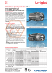
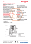
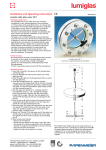
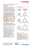
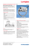
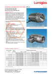
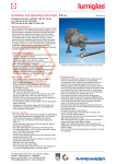
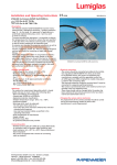
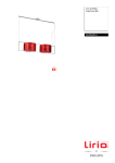
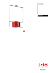
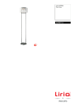
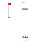
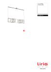
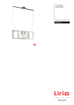
Installation and Operating Instructions
0158
Lumiglas luminaire type USL 05-Ex/USL 05-Ex-LED
II 2G Ex d IIC T3/T4/T6/120°C
II 2D Ex tD A21 IP67 T195/T130/T80/T120°C
•Important, please note:
Sight glass luminaires are specifically designed and solely intended for mounting with or onto flanged sight glass
fittings. Under no circumstances should a sight glass
luminaire be used on its own as a lid or cover for vessel
openings or as a substitute for the cover flange or the
complete sight/light port. Luminaires for use in potentially explosive environments must be mounted, installed and
serviced by staff who have the relevant qualifications and have been properly trained for this type of work.
Please observe the data set out in the EC type-examination certificate!
•General operating conditions:
- Independent of pressure/vacuum in the vessel
- Approved for use in Ex environments:
Gas: Zones 1 and 2
Dust: Zones 21 and 22
- Approved for use in ambient temperatures between
-20°C and +60°C or +40°C, depending on the lamp fitted (see type plate and temperature classification parameters).
•Electrical data, general:
-Voltage, power, temperature class and protection rating
are shown on the type plate.
-Ex approval acc. to EC type-examination certificate:
BVS 08 ATEX E 133
II 2G Ex d IIC T3/T4/T6/120°C
II 2D Ex tD A21 IP67 T195/T130/T80/T120°C
-The variant with integrated transformer is PTC-protected; no fuse replacement necessary
-Power supply: AC or DC voltage, depending on lamp fitted
-Caution: Only alternating current should be used for
luminaires with a built-in transformer.
-Warning: Over-voltage will cause premature lamp failure!
-10% voltage tolerance is admissible
-Please note: Flash frequency if used as a flash-lamp is ≤ 1 Hz
Application as combined sight and light port on a sight glass fitting
acc. to DIN 28120, mounting by way of hinged bracket.
•Parameters/Temperature classification: No.
Type USL 05-Ex
Type USL 05-Ex-LED
Variant
Part No.
Voltage
Volt
Built-in
transformer
Halogen lamp
or LED illuminant
Voltage Socket
Ambient temperature range
-20°C ≤ Ta ≤ +40°C -20°C ≤ Ta ≤ +60°C
1
(12 V) 5 W
3540.031.00
12 .
without
12 V/5 W
G4
2G T6
2D T80°C
2G T4
2D T130°C
2
(120 V/12 V) 5 W
3540.032.00
120 ,
with
12 V/5 W
G4
2G T6
2D T80°C
2G T4
2D T130°C
3
(230 V/12 V) 5 W
3540.033.00
230 ,
with
12 V/5 W
G4
2G T6
2D T80°C
2G T4
2D T130°C
5
(12 V) 20 W
3540.035.00
12 .
without
12 V/20 W
G4
2G T4
2D T130°C
2G T3
2D T195°C
6
(24 V) 20 W
3540.037.00
24 .
without
24 V/20 W
G4
2G T4
2D T130°C
2G T3
2D T195°C
7
(24 V) 20 W
3540.036.00
24 .
without
24 V/20 W
G4
2G 120°C
2D T120°C
–
–
8
(24 V) 20 W (f≤1Hz)
3540.038.00
24 .
without
24 V/20 W
G4
2G 120°C
2D T120°C
–
–
9
(230 V) 4 W-LED
3540.059.00
230 .
without
230 V/4 W-LED
GZ10
–
–
2G T6
2D T80°C
4
F.H.Papenmeier GmbH & Co. KG · division Lumiglas
Talweg 2 · 58239 Schwerte · GERMANY
phone: +49-2304 205-0 · fax: +49-2304 205-206
[email protected] · www.lumiglas.de
•Electrical connection:
Conditions/requirements: This Ex-type luminaire has been manufactured with a permanently connected cable.
The free ends of this lead must be installed in a category 2G/2D enclosure if connection is to be carried out in a
potentially explosive environment.
The luminaire and the area around the installation site should be cleared of dust prior to installation and in the course of maintenance work. The dismantled parts should be protected against dirt, dust and contamination during installation or servicing work. When closing the luminaire, special attention should be paid to ensure that the interior of the lamp is free of dust.
Part No.
1 External protective
conductor terminal
2 Locking screw
3 Safety tab
4 Screw-in glass lens
- The cable has already been connected inside the luminaire by the manufacturer and is ready for use.
- The external protective terminal (1) must be connected to a separate operational earth.
- The connecting cable should be secured after max. 1 m.
- Caution! If the cable is being replaced, e.g. by one of a
different length, the inner terminals need to be loosened before unscrewing the cable gland.
•Replacing lamp:
•Mounting by way of hinged bracket:
- Switch off power.
The hinged bracket is used to secure the luminaire to the - Allow sufficient time to cool down, see type plate.
cover flange of a circular sight glass fitting (also suitable - Undo locking screw (2) which releases the safety tab (3) for for visual flow indicators). Alternatively, it can be attached the screw-type glass lens (4).
to the slotted cover nut of screw-type sight glass fittings
- Unscrew glass lens (4) using only the special claw spanner.
to DIN 11851.
- The defective lamp is then pulled out (2-pin type) or removed The hinged bracket is fixed in place by turning the supplied with a press-and-twist movement (GZ10 bayonet type).
M6 bolt into a blind hole which has previously been tapped - Hold the new lamp bulb (original products only, please) in the pitch circle of the cover flange face. An additional using a protective cloth – taking care not to touch it with
option is to weld on the bracket.
your bare fingers. Carefully insert the replacement lamp: push the 2-pin bulb into its socket, or push-and-twist bayonet •Mounting by way of flanged adapter collar:
type lamps. Make sure the lamp is securely in position!
The flanged adapter collar is bolted or welded to the
- Before closing the luminaire, re-lubricate the thread of the slotted cover nut (DIN 11851).
screw lens (e. g. with AEMA-SOL 6 from A.E. Matthes).
- Refit the glass lens (4) by screwing it into place until it is •Please note:
tight again (pressure on O-ring).
Fastening and mounting elements, claw spanner, etc.
- The glass lens (4) is locked into position once the safety
should be ordered separately if needed.
locking tab (3) engages in one of the notches.
- Retighten the locking screw (2).
•Replacement parts:
Part No.
Screw-type lens (light aperture) with reflector 1774.022.00
•Warning:
Screw-type lens (light aperture) without
When replacing lamp bulbs, make sure that the light beam
reflector
1774.030.00
is evenly distributed over the glass lens as prescribed by the O-ring seal (Viton)
0862.036.00
design. On no account should a ‘hot spot‘ be allowed to
occur outside the luminaire (caused e. g. by the incorrect
Lamp socket G 4 (2-pin)
1202.011.00
position or condition of the lamp).
Lamp socket GZ 10
1202.024.00
•Mechanical installation:
Cable entry gland
The luminaire is attached to the cover flange of a circular
complete with 2 m connecting cable
1084.013.00
sight glass fitting or visual flow indicator using the hinged
complete with 5 m connecting cable
1084.015.00
bracket. With the screw-type sight glass fitting, the luminaire
complete with 20 m connecting cable
1084.017.00
is attached to the slotted cover nut; alternatively, it can be
mounted using a hinged bracket or a flanged adapter collar.
(Halogen) lamps / LED illuminant:
24 V/20 W – G4
3232.206.00
•The Lumiglas luminaire Type USL 05-Ex is suitable for sight 24 V/20 W – G4 (reflector spot lamp)
3232.222.00
glasses in the following nominal sizes, using the appropriate 12 V/20 W – G4
3232.229.00
mounting:
12 V/5 W – G4
3232.221.00
230 V/4 W – GZ10-LED
3232.004.00
Type of fitting
from Hinged bracket Flanged adap
ter collar
Circular sight glass fitting DN
•Accessories: Claw spanner
6816.001.00
DIN 28120
DIN 28121
Visual flow indicator
Screw-type sight glass fitting
similar to DIN 11851
25…
40…
50…
65 80
100
125
+
+
+
+
+
+
+
–
–
–
+
+
–
–
•Servicing:
- Keep luminaire clean.
- Keep note of average lamp life.
- Use only original replacement parts.
All dimensions in mm unless stated otherwise. Subject to change without prior notice.
ric 11.09 0093.027.00
F.H.Papenmeier GmbH & Co. KG · division Lumiglas
Talweg 2 · 58239 Schwerte · GERMANY
phone: +49-2304 205-0 · fax: +49-2304 205-206
[email protected] · www.lumiglas.de