1
Installation and Operating Instructions
0093.104.00 c
UL-Listed Lumiglas Luminaires USL 08-Ex
+C
T3B, T4A
•General notes on safety:
-Read these instructions as well as data sheet USL 08-Ex
thoroughly before commencing work on the unit and keep it handy for reference during installation.
-When installing the luminaire it is vital that it is totally
sealed to explosion proof standard before switching it on.
-Any unused entry holes left after correct installation
procedure must be sealed with suitable plugs (included in delivery). These plugs conform at least to requirements of Class l, Div. 1 & 2, Group C & D for explosion hazardous areas.
-For luminaires with 35 and 50 W lamps use only cabling
approved for use at 90°C and for luminaires with 100 W
lamps only cabling approved for use at 110°C.
-Before unbolting a flange from the sight port ensure the
vessel is empty and not under pressure, that the plant
is switched off and that it remains switched off and safe
whilst the work on the sight port proceeds.
-When drilling the flange for luminaire carrier brackets,
ensure that any securing screw can never protrude beyond the flange face and touch the glass disc. That can lead to glass failure later.
-Do not work on the luminaire without clear instructions
from the safety engineer responsible for the type work.
Only work on sight glass and luminaire if you have had the appropriate training.
-Never exchange a lamp with one of a higher wattage e. g. a 35 W by a 50 W lamp. That can lead to dangerous increase in luminaire temperature and exceeding the specified temperature class.
•Mechanical installation:
Ensure that the vessel is not under pressure, the plant
is switched off and that it remains switched off and safe whilst work proceeds on the sight port. Have the installation instructions for the sight glass handy and dismantle the sight
glass precisely according to those instructions:
-Clean area around the sight glass so that sealing faces
remain clean.
-Remove cover flange, loosening each nut a little at a time in diametrically opposed sequence so as not to distort flange.
-If the glass sticks to the base flange, do not disturb it.
-If glass sticks to cover flange, carefully ease it off.
-Clean the cover flange and drill and tap two blind M8 holes for the luminaire carrier bracket.
IMPORTANT: See diagrams on page 1 and 2 for details.
-Check each gasket and replace any damaged ones
-Refit the cover flange in accordance with makers
instructions and DIN 28120 or 28121.
-IMPORTANT: Avoid any distortion of the flange by
tightening nuts to recommended torque; the values depend on sight glass diameter and materials and are given in the relevant data sheet. Tighten nuts in
diametrically opposed sequence.
-After installation, the sight glass must be thoroughly
checked for any leakage. Please refer to all standards and regulations pertaining to work on pressure vessels.
F.H.Papenmeier GmbH & Co. KG · division Lumiglas
Talweg 2 · 58239 Schwerte · GERMANY
phone: +49-2304 205-0 · fax: +49-2304 205-206
[email protected] · www.lumiglas.de
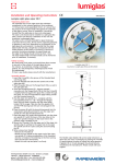
•Mechanical installation of carrier brackets (to be ordered
separately) and luminaires:
Fixing with straight
carrier brackets,
for use on
lighting port only
Fixing with cranked
carrier brackets, for use
with combinded light
and sight port
min. Ø 120
max.Ø 150
Ø 210
min. Ø 140
max.Ø 175
Ø 240
min. Ø 170
max.Ø 175
Ø 280
•Threaded holes for carrier brackets:
-Mark position of threaded holes in accordance with
diagramm above.
-Never drill on a smaller pitch circle diameter than that given above! That can lead to damage of the sight glass and eventual glass failure.
-The lateral spacing of the M8 threaded holes depends on the sight glass size and is automatically determined when the holes are positioned as per diagram.
-The core diameter of the holes is 6.8 mm; if the cover
flange is 20 mm or less thick, the holes should be drilled through. If the cover flange is thicker than 20 mm,
clearance depth of the hole should be 18 mm and thread taken to 15 mm depth.
•Installation of carrier brackets:
-Caution: Do not look into light – Danger of impaired
eyesight!
-Before fitting the carrier brackets, refit the sight glass cover
flange, ensuring the nuts are tightened in diametrically
opposed sequence to avoid distorsion.
-The bracket feet have elongated holes that enable the brackets to be set for width of the luminaire body.
-Fit the carrier brackets using bolts, spring and flat washers
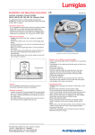
(included in delivery) as shown in adjoining sketch
-The flat washer is important! It supports the spring washer
so that it remains loaded in any position over the elongated
hole.
-Fit the luminaire, using the remaining bolts and spring
washers, between the brackets.
•Electrical installation:
-First complete the mechanical installation.
-The luminaire is earthed via the cable conduit.
Power supply is 120 V AC.
-Caution! These luminaires should only be connected by
electricians suitably qualified for work in explosion
hazardous areas.
•Wiring:
-Unscrew luminaire cover W from terminal box.
-Fit cable conduit to one or other of the three cable entries and screw in at least to depth of five full threads. Any
remaining entry to be sealed by explosion proof plugs P
supplied (see under “General notes on safety”).
-Cover the thread of plug P with lubricant grease before
fitting (e. g. with AEMA-SOL 68).
-Pass cable through conduit into terminal box and secure
cores to both terminals.
-Check terminal box gasket for any damage and renew
if necessary, then screw on cover W and tighten.
Screw M8 x 20
Carrier bracket
Spring washer
Flat washer
Elongated hole
Cover flange
P
W
•Caution! Never switch the luminaire on, even for test
purposes, until it is fully sealed to explosion proof state.
7
Terminal box
7 = 3 x entries
threaded NPT
(right, lleft or top)
Advantage: easy
connection
Cable terminal for 120 V AC
F.H.Papenmeier GmbH & Co. KG · division Lumiglas
Talweg 2 · 58239 Schwerte · GERMANY
phone: +49-2304 205-0 · fax: +49-2304 205-206
[email protected] · www.lumiglas.de
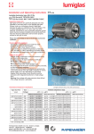
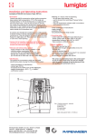
•Dimensions and components of Lumiglas luminaires USL 08-Ex:
4a
7
7
4a
6
6
3
4b
3
5
1
2
1
2
Terminal box open
Cover (4b) removed
Item
1
2
3
4a
4b
35 W or 50 W Lamp
Socket E 26
Part
Luminaire body
Screwed lens ring
Terminal box with terminal block
Acess cover for lamp exchange
Acess cover for cable connection
Item
5
6
7
•Lamp exchange:
-Switch off power to luminaire
-Unscrew cover (4a)
-Loosen screw (5)
-Withdraw lamp socket angle bracket assembly (6)
complete with lamp
-Unscrew (E 26) or pull out (BA 15d) defective lamp
-Fit new lamp
4b
3
5
1
2
50 W or 100 W Lamp
Socket BA 15d
Part
Screw with self locking nut for lamp socket
Lamp socket – angle bracket assembly
3 x 1/2 in NPT threaded cable entry holes for
alternative cable connection
-Refit lamp socket angle bracket assembly (6) with lamp
-Tighten screw (5)
-Check terminal box gaskets for any damage and renew if
necessary, then screw on cover (4a) and tighten
-Switch power on
•Replacement parts for Lumiglas luminaires USL 08-Ex:
Description
Part No.
Description
Halogen Lamp
Voltage/type
Part No.
Socket
Housing cover part 4a/4b
0823.092.00
120V/ 35 W Spot
E 26
3232.248.00
Threaded lens ring 2 (without glass)
1350.044.00
120 V/ 35 W Flood
E 26
3232.251.00
Glass disc (for luminaire with socket E26) for part 2
1775.142.00
120 V/ 50 W Spot
E 26
3232.249.00
Glass disc (for luminaire with socket BA 15d) for part 2
1775.168.00
120 V/ 50 W Spot
BA 15 d
3232.275.00
Threaded ring for part 2
5692.008.00
120 V/ 50 W Flood
E 26
3232.252.00
O-ring gasket (silicon), d – 90 x 2.5 (for part 4a/4b)
0862.065.00
120 V/100 W Spot
BA 15 d
3232.272.00
O-ring gasket (silicon), d – 110 x 3 (for part 2)
0862.072.00
Reflector (Spot) für socket BA 15d
5904.014.00
Lamp socket E 26
1202.020.00
Lamp socket BA 15d
1202.013.00
F.H.Papenmeier GmbH & Co. KG · division Lumiglas
Talweg 2 · 58239 Schwerte · GERMANY
phone: +49-2304 205-0 · fax: +49-2304 205-206
[email protected] · www.lumiglas.de
All dimensions in mm unless stated otherwise. Subject to change without prior notice. 02.14
F.H.Papenmeier GmbH & Co. KG · division Lumiglas
Talweg 2 · 58239 Schwerte · GERMANY
phone: +49-2304 205-0 · fax: +49-2304 205-206
[email protected] · www.lumiglas.de