1
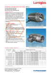
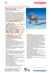
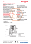
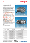
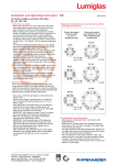
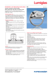
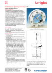
Installation and Operating Instructions 0158 0093.064.00 b VISULEX Ex-Camera K25ZP-Ex/K25ZN-Ex II 2G Ex de IIC T6 Gb II 2D Ex tb IIIC T80°C Db •Description: The VISULEX Camera K25ZP-Ex/K25ZN-Ex has been manufactured with a flameproof enclosure – ignition protection type ’d’ – for the body. It is approved for applications in potentially explosive (Ex) areas, zones 1 and 2 as well as zones 21 and 22. To ensure trouble-free operations, it is essential to observe the temperatures for the built-in camera that are specified in the data sheet. The relevant control panel is connected to the Ex-camera outside the Ex hazardous area. Ex cameras are intended for property surveillance as well as for the remote monitoring of technical processes in reactors, apparatus, vessels, etc. They are purpose-designed and are specifically for mounting on sight glass flange fittings. Important, please note: Under no circumstances should a camera be used to replace the cover flange or the com plete sight glass fitting, nor should it be used on its own as a closure for a vessel port. Cameras for potentially explosive areas should only be mounted, installed and serviced by personnel who have been expressly trained for this work and authorised to do the job in each case. •General electrical data: -Feed voltage to the camera: 24 V/DC ± 10% -Maximum power consumption: 20 W -Protection class: IP65 acc. to EN 60529/DIN VDE 0470, Part 1 -Ex approval acc. to EC type examination certificate: BVS 08 ATEX E 131 II 2G Ex de IIC T6 Gb II 2D Ex tb IIIC T80°C Db •Markings: The camera has a permanent type plate which is clearly visible and easy to read. It bears the following data: -Name and address of manufacturer -Camera type: K25ZP-Ex or K25ZN-Ex -Explosion protection classification -Ambient temperature range: -20°C ≤ Ta ≥ +40°C -Certificate number -Warnings which much be observed: -Do not open when power is on -Even after the power has been switched off, wait four minutes before opening -Use only heat-resistant cables as specified in the operating instructions -Serial number/year of manufacture -Supply voltage -Protection class: IP65 -CE symbol/certification body number •Connecting cable: -Shielded control cable 3P x AWG 20 C, black (Metrofunk) or equivalent cable of another make should be used. -Heat-resistance: min. -20°C to + 90°C; flame-inhibiting or flame-retardant! - The camera is supplied with 5 metres of connecting cable as standard. F.H.Papenmeier GmbH & Co. KG · division Lumiglas Talweg 2 · 58239 Schwerte · GERMANY phone: +49-2304 205-0 · fax: +49-2304 205-206 [email protected] · www.lumiglas.de VISULEX Ex-Camera K25ZP-Ex with zoom lens •Electrical connection: - The camera should be connected according to the installa- tion regulations DIN EN 60079-14 in force at the time. -In its standard version, the camera is supplied by the manufacturer complete with the approved control line. -An ATEX-approved, EMC-compliant Ex d cable entry gland is used for the connecting cable. -The external protective conductor terminal (part 2) must be connected to a separate earthing terminal. -The camera is protected by fuses in the external control unit (located in the non-explosive area). -These fuses should only be changed after the system has been switched off and only by personnel who have been trained and authorised to do so. •Changing the camera and/or electronics: Any replacement of the camera assembly should be carried out by the manufacturer and/or be done at the manufacturer’s works (Papenmeier). Part 1 2 3 4 5 •Mechanical installation: It is essential to read the information sheet “Important instructions when using sight glass fittings” before commencing installation work. The Ex camera is attached to the cover flange of a circular sight glass fitting or flow sight glass or to the slotted cover nut of a screw-type sight glass using the mounting components provided. On no account should the lens of the camera be exposed to direct sunlight as this will render it inoperable! The VISULEX Ex-Camera K25ZP-Ex/K25ZN-Ex fits the follow- ing nominal diameters when used together with the appropriate mounting parts: from DN Hinged Flanged bracket adapter collar 25 + – 40 + – Flow indicator sight glasses 50 + – Screw-type sight glass fitting in line with DIN 11851 65 – + 80 + – Type of fitting Circular sight glass fitting DIN 28120 + DIN 28121 Protective conductor terminal Locking screw Safety tab Screw-type glass lens Cable entry gland M20 x 1.5 (Ex ‘d‘) •Mounting by flanged adapter collar The adapter collar is secured to the slotted cover nut (DIN 11851) by welding or screwing it on. •Replacement parts: Product Part No. Screw-type sight glass 1774.099.00 O-ring seal0862.073.00 •Accessories: Product Camera mounting (hinged bracket) Camera mounting (flanged adapter) Claw spanner for screw-type sight glass, for opening the camera Part No. 0354.019.00 1356.007.00 6805.001.00 •Maintenance: -Keep the camera clean. -After opening the camera, the thread of the screw-type glass lens (part 4) should be freshly greased, (e.g. with AEMA-SOL 6 B, made by A.E. Matthes). -Clean the glass disc regularly to ensure optimum camera vision. -Always use original replacement parts. •Mounting with hinged bracket: The hinged bracket is intended for fastening the camera to the cover flange of a circular sight glass fitting or flow sight glass or to the slotted cover nut on screw-type sight glass fittings acc. to DIN 11851. The hinged bracket is secured to the required bolt circle using the M8 screw included in the scope of supply which fits into a previously tapped blind hole. Alternatively, the hinged bracket can be welded in place. Subject to change without prior notice – Dimensions in mm unless otherwise stated. 11.14 F.H.Papenmeier GmbH & Co. KG · division Lumiglas Talweg 2 · 58239 Schwerte · GERMANY phone: +49-2304 205-0 · fax: +49-2304 205-206 [email protected] · www.lumiglas.de