1
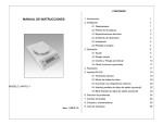
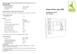
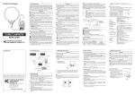
INSTALLATION AND OPERATION MANUAL
FOR PELLET BOILER „CL 35”
2
CONTENT
I.
1.
OPERATION MANUAL FOR PELLET BOILER „CL 35”
Description, main characteristics and accessories for pellet boiler „CL 35”
p.3
1.1.
Technical data
p.3
1.2.
Main parts of the boiler
p.4
2.
Requirements for the pellets
p.4
3.
Instruction how to work with the boiler:
p.5
4.
3.1.
Turn the boiler on/off
p.5
3.2.
Schemes of menus
p.6
3.3.
Description of menus
p.7
3.4.
Emergency shutdown of the boiler
p.9
Preventive maintenance
p.9
4.1. Cleaning of the combustion chamber
p.9
4.2. Annual maintenance
p.9
5.
Guarantee maintenance
p.10
II.
SERVICE INSTRUCTION FOR PELLET BOILER „CL 35”
1.
Installation requirement:
2.
3.
p.11
1.1.
Requirements for the chimney
p.11
1.2.
Requirements for the heating installation
p.11
1.3.
Requirements for the technical room
p.11
Assembly and installation
p.12
2.1.
Transporting boiler to the client
p.12
2.2.
Transporting to the technical room
p.12
2.3.
Leveling of the boiler
p.12
Hydraulic and electrical schemes. Configuration for installation.
p.13
3.1.
Hydraulic schemes
p.13
3.2.
Electrical schemes
p.14
4.
Service menu of the controller
p.15
5.
Parameters to set the controller
p.16
6.
Initial start up
p.18
7.
6.1.
Loading the boiler
p.18
6.2.
Initial startup. Configurations.
p.18
Ash collector (option)
p.21
www.tangra.bg ; +359 2 925 06 10; 174 Europa Blvd. 1331 Sofia, Bulgariа
3
1.
Safety instruction
This appliance is not intended for use by persons (including children) with reduced physical, sensory or
mental capabilities, or lack of experience and knowledge, unless they have been given supervision or
instruction concerning use of the appliance by a person responsible for their safety.
The boiler is installed in separate rooms with floor and walls of fire-resistant material, with sufficient
flow of fresh air.
The boiler is installed and works only in areas without high humidity. It is not acceptable to exposed the
boiler to dripping or splashing water.
Cleaning the boiler is dry or lightly moistened with water or neutral detergent cloth. The use of abrasive
or aggressive pochistvashi preparations.
Do not allow installation of the boiler on pallet.
Installation and putting into operation of the boiler must be carried out by trained and authorized by the
manufacturer installers.
When connecting the boiler to the electrical supply, it should provide a tool of exclusion from power,
which provides separation of contacts for all poles in terms of overvoltage category III. Appropriate tool
is bipolar circuit breaker 6A 250V.
Connecting the boiler to the electric supply must be carried out by a specialist and with solid connection.
It is not allow using plug-type "Schuko" or other type of connection to the electrical supply.
Turn on/off the boiler is made from pole circuit breaker located in the power supply.
Turn on/off the boiler from the main supply to the boiler is done with the key that is located on the right
of the control panel. This key is single-pola and provides on / off only of the phase conductor.
Functionaly turn on / off the boiler is done by pressing the On / Off key, which is located on the control
panel.
If the power cable of the appliance is damaged, it must be replaced by the manufacturer, its service
agent or a similarly qualified person to avoid danger situation.
Recommended once a week to check the combustion chamber and, if necessary, to clean the collected
ash with the shovel and pan, included in the package.
Once a year is made mandatory maintenance, which includes testing of all systems, general cleaning of
the burner, combustion chamber, heat exchanger tubes, and upper smoke collecting camera, check all
connections for leaks, check all electrical connections, check the flexible hose for compressed air and
pellets.
www.tangra.bg ; +359 2 925 06 10; 174 Europa Blvd. 1331 Sofia, Bulgariа
4
2.
Description and main characteristics
„CL 35” is steel single-thread water pellet boiler equipped with electro pneumatic self-cleaning
system.
The boiler consists of two separate modules – boiler body and storage tank for pellets. As an
option, it is possible to install ash collector for automated collection of the ash.
CL 35 is designed especially for heating systems in single family houses, small residential and
office buildings, services, workshops etc.
2.1.
Technical data
Parameter
Measure
CL 35
-
-
Value
Capacity
kW
17 - 35
Total weight
kg
170
Water volume
L
120
Flue gas connection
mm
150
Volume of the pellet storage tank
kg
220
Overall dimensions :B х L х H
mm
980/800/1300
Working pressure of water
Atm.
2
Boiler test pressure
Atm.
4
Recommended water working temperature
о
C
80/60
Maximum water temperature
о
C
90
Under pressure needed in the chimney
Pa
15
Joined dimensions – water in / out
“
1¼
Joined dimensions – drain connection
“
½
Power supply
V
220
Electrical capacity
W
550
Nominal electrical capacity
W
120
Protection degree
-
IP20
Efficiency
%
Up to 94
www.tangra.bg ; +359 2 925 06 10; 174 Europa Blvd. 1331 Sofia, Bulgariа
5
2.2.
Main parts of the boiler type „CL 35”
1
2
3
4
5
6
7
8
1)
2)
3)
4)
5)
6)
7)
8)
Connections to the heating system;
Controller;
Boiler;
Auger for automatic supply of the burner with fuel;
Pellet storage tank;
Compressor;
Burner;
Ach collector (option)
3.
Requirements to the pellets – „CL 35” is designed to work with wood pellets, with diameter 68mm, length 5-30mm and moisture content – 5-9%.
With his integrated automatic burner cleaning system, as well as the module for forced cleaning of the
burner, this boiler is not pretentious about the quality of the pellets. It works with all type of wood
pellets intended for domestic usage, according to the ÖNORM M7135, DIN 51731, DIN Plus standards.
Regardless of the pellets, which are used, after correct adjustment of the combustion process could be
reached efficiency of 90-94% and low emission of greenhouse gases CO, CO2 and NOX.
In case of changing the quality of pellets or the supplier during the exploitation, the parameters of the
combustion process should be reset. This should be done only by authorized service organization.
There is a possibility to save up to three different setting for different quality of pellets.
www.tangra.bg ; +359 2 925 06 10; 174 Europa Blvd. 1331 Sofia, Bulgariа
6
4.
Instruction how to work with the boiler:
4.1.
Turn the boiler on/off – It is done by holding the button On/Off
Alarm Servicing
Power
Alarm Cleaning
Temperature
Fuel
Alarm – no
fuel
Time
Setup
Edit
buttons
Cancel
On/Off
Enter
Display
Menu button
TANGRA capacitive touch keyboard is designed for intuitive use.
Keep the keyboard clean. Any contamination could send signal for pressed button.
At the top of TANGRA keyboard are located indicators for various alarms and menus.
The display shows the set or current values for the currently selected menu option. With buttons you can
navigate through the menu and control the operation of TANGRA controller. Refer to the Table on next
page for descriptions of the buttons.
The following sound alarms are available:
• Short high tone: sounds when navigating the menu and editing the settings;
• Long low tone: sound in case of invalid operation (wrong button pressed);
• Long high tone: in case of alert, this tone sounds with the user defined loudness, and in case of an
error, this tone sound with 100% loudness.
www.tangra.bg ; +359 2 925 06 10; 174 Europa Blvd. 1331 Sofia, Bulgariа
7
4.2.
Scheme of the main menu:
www.tangra.bg ; +359 2 925 06 10; 174 Europa Blvd. 1331 Sofia, Bulgariа
8
4.3.
Description of the menus
www.tangra.bg ; +359 2 925 06 10; 174 Europa Blvd. 1331 Sofia, Bulgariа
9
4.4.
Emergency boiler shutdown:
www.tangra.bg ; +359 2 925 06 10; 174 Europa Blvd. 1331 Sofia, Bulgariа
10
Emergency stop button
(Turn off whole power supply of
the boiler)
Emergency stop button should be used only in case of accident. Turning the boiler off with
the emergency stop button can affect the operation of the unit and it is not recommended by
the manufacturer!
5.
Preventive maintenance:
5.1. Cleaning of the combustion chamber – accumulation of ash depends mainly of the quality of the
pellets and operation hours of the boiler. The boiler is supplied with tray and blades to collect the ashes.
We recommend once a week to check the amount of ash, collected at the bottom of the combustion
chamber and if necessary to clean it.
5.2. Annual maintenance – this should be done once a year or after 5 tones of pellets are burned. The
annual maintenance should be done by authorized organization. This includes testing of the systems and
general cleaning of the burner, combustion chamber, pipes and upper flue gas chamber.
Annual maintenance is a compulsory part in connection with warranty service.
In case of rejection, incorrect work, alarm messages on the display you should contact your service
provider and follow his instruction. You can also receive additional help and instructions from the
manufacturer using the contacts mentioned below:
Tangra AV Ltd.
Address: 174, Europa Blvd.
1331 Sofia, Bulgaria
Phone: +359 2 9250610
www.tangra.bg
[email protected]
www.tangra.bg ; +359 2 925 06 10; 174 Europa Blvd. 1331 Sofia, Bulgariа
11
6. GUARANTEE CONDITIONS
The manufacturer guarantee correct and flawless work of the unit when the installation and operating
instructions are followed and the unit is installed from a certified by the manufacture company.
The guarantee starts from the date, when the guarantee card is filled and stamped. The guarantee card
should be submitted in three copies, an original for the client and two copies, saved in the installation
and manufacture companies. When the installation is complete the installer should return a copy of the
guarantee card to the manufacturer.
THE GUARANTEE IS NOT VALID in case of:
Damages on the unit caused by incorrect storage, transportation not done by the manufacture
company;
Damages caused by nature disasters (earthquake, fire, flood, etc.);
The instructions for installation, operation and maintenance are not followed;
Repairs from the buyer himself or an unauthorized maintenance company;
Changes in the construction of the unit;
Units, which capacity is not correctly selected;
Damages caused by unexpected factors, for which the manufacturer is not responsible.
Every warranty repair should be documented in the guarantee card of the client and the installation
company, which should inform the manufacturer for the repairs, if some part(s) need(s) to be changed.
Guarantee period is interrupted for the period of time from the claim until the repair of the damage.
The guarantee period of each unit is 24 (twenty four) months.
The guarantee period of hydraulic density of the unit is 60 (sixty) months.
The guarantee is valid if the customer presents the original guarantee card and the invoice.
www.tangra.bg ; +359 2 925 06 10; 174 Europa Blvd. 1331 Sofia, Bulgariа
12
SERVICE INSTRUCTION FOR PELLET BOILERS „CL 35”
1.
Installation requirements
1.1. Requirements for the chimney – Water heating pellet boiler „CL 35” should be connected to the
insulated system to take the flue gases off. This system should be made of non-combustion materials
with minimum diameter ф150mm.
Requirements for the heating installation – The installation of the water heating boiler „CL 35”
1.2.
should be done only by qualified specialists, certified as installers by the manufacturer. According to BDS
EN 303-5/2000 should be connected to the following systems:
High-temperature (until 90oC) closed water heating system with open or closed expansion tank,
with maximum working pressure 2bar. When the system is supplied with closed expansion tank, it
should be with minimum volume 35 l and pressure safety valve up to 4bar.
Low-temperature (until 55oC) water heating system (under floor heating or fan coil units) closed
or opened type. Mixing unit should be installed in order to decrease the temperature of the water
after the boiler..
The boiler should not work with water temperature under 55oC. In this case the guarantee is
not valid!
1.3. Requirements for the technical room
The pellet boiler „CL 35” should be installed in a special technical room, which floor and walls are made
of non-combustion materials with good ventilation and enough quantity of fresh air for the combustion
process.
Installation – burner on the right side
Installation – burner on the left side
Normally, the boiler is produced with burner on the right side, but it could be easy installed
on the left side, if it is necessary.
It is forbidden to install the boiler in living rooms, corridors, etc.
www.tangra.bg ; +359 2 925 06 10; 174 Europa Blvd. 1331 Sofia, Bulgariа
13
2.
Installation of pellet boiler „CL 35”
2.1 Transportation of the boiler to the client:
The transportation of the boiler should be done in a reinforced vertical position in the original
packing and transport pallet, in order to avoid transport damage of the level system and the external
covers.
2.2. Transporting to the technical room should be done by using a pallet truck with the original transport
pallet. In the technical room this pallet should be removed and the boiler could be moved on a wheel,
mounted on the back side of the boiler.
2.3. After the boiler and the storage tank are placed in the technical room, both units should be
leveled, using the leveling screws, showed on the scheme below:
Left leveling screw
Back leveling screw
Right leveling screw
It is forbidden to install the boiler in the technical room on the transport pallet!
The boiler could be installed directly on the floor, which is made of non-combustion materials or
previously reinforced if required.
www.tangra.bg ; +359 2 925 06 10; 174 Europa Blvd. 1331 Sofia, Bulgariа
14
3.
3.1.
Hydraulic and electrical schemes. Configuration for installation.
Hydraulic scheme
3.2. Electrical schemes
Connection to the electrical system should be made by qualified specialist according to BDS EN 60 3351/1997
Main electric supply 230V/50Hz is fed on terminals L, N и PE. It should be connected by hard connection
and separate safety fuse.
It is not allowed to use Schuko plug or other type.
www.tangra.bg ; +359 2 925 06 10; 174 Europa Blvd. 1331 Sofia, Bulgariа
15
As standard, the controller has one output for control of one circulating pump. In case you
install more than one pump, should be used additional control panel, which is available as an
option to the boiler.
www.tangra.bg ; +359 2 925 06 10; 174 Europa Blvd. 1331 Sofia, Bulgariа
16
www.tangra.bg ; +359 2 925 06 10; 174 Europa Blvd. 1331 Sofia, Bulgariа
Възможни грешки:
Е001-Keyboard error; E004 – Motherboard communication error; E108 – security switch error; E110 – NTC1 error – temperature sensor; E111 – TC1 error – temperature flue gas; E115 – General error;
А004 – low battery; А002 – service required; А003 – low air flow
4. Service menu of the controller
16
17
5. Parameters to set the controller
Nº
para
mete
r
0
1
3
4
10
18
19
20
21
22
24
28
50
51
55
57
60
61
62
67
68
Description
Measure
Maximum wait time for successful firing in ignition phase.
minutes
Maximum acceptable time for flame detection with igniter off in
minutes
the test fire phase.
Start Up phase auger OFF time – defines the heater OFF time (no
10 = 1 s
dosing) during the Start Up phase.
Start Up phase auger ON time – defines the feeder ON time
10 = 1 s
(dosing) during the Start Up phase.
Power 1 auger ON time – working dose at power level 1.
Power 5 auger ON time – working dose at power level 5.
Air quantity in Fire down phase.
After Fire down phase is executed, the fan accelerates to full
speed for 20 seconds.
Air quantity in Test Fire phase
Air quantity in Start Up phase
Air quantity in Ignition phase
Air quantity at power 1.
Air quantity at power 1.
Temperature difference between Tgiven and Tcurrent, by reaching of
which the controller starts fire up.
o
C
Example: if Т1=65оС and parameter 50=10оС, the boiler will
о
restart at Т1=55 С.
Tgiven – required water temperature in the boiler. When Tgiven is
reached, the controller starts smooth reduction of burner power
from level 5 down to level1 and at [Tgiven+5oC] the burner is
o
C
switched off.
Example: if T1 is set to 65oC, the boiler will stop completely at
70oC.
Gasses modulation start temperature - flue gasses temperature
o
threshold, when the controller begins to decrease the burning
C
power, independently from the water temperature in boiler.
Alarm triggering gasses temperature:
If the flue gasses temperature is higher than [PAR57*2], the
Alarm Gasses is reported and the controller switches off the
system.
Time between two blow cleanings.
minutes
Blow cleaning period.
s
Air quantity during blow cleaning period:
o
Water pump turn on temperature.
C
Water pump turn off temperature. MUST BE lower than PAR67
o
C
value.
Limits
of Recommen
values
ded values
1 ÷ 20
15
1÷5
1
0 ÷ 200
150
0 ÷ 200
100
10 ÷ 40
10 ÷ 60
50 ÷ 150
20
35
70
150=max.
10 ÷ 150
10 ÷ 50
10 ÷ 50
10 ÷ 50
10 ÷ 150
60
20
20
20
60
5 ÷ 20
5
50 ÷ 82
65
150 ÷ 200
180
100 ÷ 150
125
0 ÷ 120
10 ÷ 120
50 ÷ 150
40 ÷ 70
60
30
100
55
40 ÷ 70
50
www.tangra.bg ; +359 2 925 06 10; 174 Europa Blvd. 1331 Sofia, Bulgariа
18
Nº
paramete
r
70
78
79
80
82
83
94
102
Description
Measure
Start Up phase duration.
OBLIGATORY REQUIREMENT (par.3+par4+par.3)>par.70
Flame present detection level - Defines the sensor input for valid
flame detection.
No flame detection level - Defines the lower sensor input level for
no flame detection.
Time delay before OFF detected - Defines the time during which
flame sensor detects value under param. 79 before the burner to
be stopped and blow cleaning started.
Minimal air quantity entering at the burner under which alarm is
activated (stuffed chimney, fan failure etc.)
Time delay before triggering pressure error - Defines the time for
air quantity to be under param. 82
Time to service warning level - Defines the Time to service due
time.
Freeze protection
s
Limits of the Recommen
values
ded values
30 ÷ 120
40
10 ÷ 200
120
0 ÷ 100
10
0 ÷ 180
60
1 ÷ 100
10
s
0 ÷ 120
30
weeks
0 ÷ 250
0
5 ÷ 30
10
s
o
C
www.tangra.bg ; +359 2 925 06 10; 174 Europa Blvd. 1331 Sofia, Bulgariа
19
6.
Start Up the boiler and initial firing.
6.1. Filling the installation, filling with fuel and check the integrity of the unit
After the installation of the boiler and its connection to the heating and electrical systems, could
proceed to filling of the boiler body and heating installation with water. All types of connections inside
and outside the boiler should be visually inspected for leaks.
To ensure enough quantity of pellets, which is needed for initial start of the pellet boiler, ½ of the
volume of the pellet storage tank should be filled.
Verify the position of the ceramic element in the combustion chamber
Verify of all electrical connections of the burner and the flexible pipe for compressed air.
Scheme for supply the burner and the compressor:
Auger feeding
Jack from the
boiler
Compressor
supply
Compressed air
supply
Burner – view from below
After inspection turn the supply on, using the main switch.
6.2.
6.2.1.
•
•
6.2.2.
•
•
•
•
•
•
•
•
Initial Startup
Initial feeding of the auger:
Take off the flexible connection for pellets from the burner;
From menu Setup choose level [6] (Manual feeding) – The initial feeding of the auger with fuel and
hold the button Enter, until the main auger is filled with fuel and the flow become stable.
Set the capacity of the boiler:
From menu Power choose Auto;
Remove the plug of the main auger of the burner;
Press and hold the button on/off, until on the display is On;
Wait minimum 60 s.;
Place a plastic bag at the end of the flexible connection;
Take out the flame sensor;
Connect the plug of the main auger to the burner. After 60 s the main auger will turn on;
Measure the quantity of pellets, passed through the main auger for 6 min. This quantity, multiplied
by 10 gives the amount of fuel in kg/h.
Capacity,
kW
Fuel,
kg/h
12.5
15
17.5
20
22.5
25
27.5
30
35
2.6
3.1
3.7
4.1
4.7
5.2
5.7
6.2
7.4
www.tangra.bg ; +359 2 925 06 10; 174 Europa Blvd. 1331 Sofia, Bulgariа
20
• Press and hold on/off button, until the display shown Off;
• Return the flame sensor. After 60-120 s the boiler will terminate loop of self-cleaning of the
burner;
If you want to change the capacity in Auto mode (highest capacity), enter in menu Setup, level
Parameters, change parameter 18, in proportion with what we want to achieve and repeat, to
establish the capacity.
Use the same procedure to set capacity 1. To set the fuel use parameter 10. We do not
recommend capacity under 17kW.
• The rest of the capacity levels (2, 3, 4) will be automatically calculated by the controller.
• Connect the flexible connection for pellets to the burner.
6.2.3. Measure the draught in the chimney:
When the boiler is not working, measure with suitable device (gas analyzer, differential manometer ) the
draught at the end of the chimney, using probe M12. The draught should not be less than 15 Pa. The
operation of the boiler with less draught than 15Pa could lead to overheating or fire in the burner.
6.2.4. Initial Start Up of the boiler:
• When we are sure, that all connections are correctly installed, the quantity of fuel for the lowest
and highest capacity are checked and there is enough draught in the chimney, we can start the
boiler from on/off button.
• From menu Temperature set the water temperature in the boiler (example75оС).
• From menu Power, set Auto. The boiler will work with maximum capacity, until it reached the set
temperature 75оС , than will star modulation of the capacity, from higher to lower and will turn off
at 80оС
• When the boiler starts, the control light, placed next to the start button, blinking. That means, that
the boiler is in ignition mode. When appeared a stable flame (3-10min), the boiler turn into
working mode and the lamp light up permanently.
• After reaching minimum 50 оС of the water in the boiler, the burning process could be set using
gas analyzer. The parameter which control the air quantity at higher capacity is 28, and at lower
capacity – 24 (check the table with parameters). Recommended values: СО – ≤100 ppm; O2≤4-8%;
λ = 1.3 – 1.6; Tflue gases ≤ 180оС.
• Repeat this procedure to set the air quantity, turning to the lowest capacity (1). Try to reach the
same values of gas analyzer.
www.tangra.bg ; +359 2 925 06 10; 174 Europa Blvd. 1331 Sofia, Bulgariа
21
6.2.5. Set the system for forced cleaning – with the system for forced cleaning of the burner, we could
set the maximum time between to cleanings, regardless if the boiler reached its set temperature.
RTC (R1) – impulse relay to set the duration of work between two cleanings (recommended values
– from 30min to 10 hours, depending of the quality of the pellets).
RTH (R2) – impulse relay to set the time, when the boiler is in Off mode, to made this cleaning
process (recommended values – from 5 to 10 min).
Setting range
Switch
Time
Position OFF – forced cleaning system
work.
Position ON – system is shunted. The
boiler does not perform forced cleaning.
Working principle – the system for forced cleaning receive signal from the ignitor. When the ignitor turn
on , RTC (R1) goes into RESET, constant light signal. After the light signal from the burner is off,
starts counting of the set time, the lamp is blinking. After the set time is over, the boiler turn off
and relay RTH (R2) count the time needed for the cleaning process. After the set time of relay RTH
(R2) is over, the boiler turn on and repeat the process.
6.2.6. Set the temperature in the boiler:
• From menu Temperature set the water temperature in the boiler. When the boiler reaches this
temperature, it will turn automatically in modulation mode and after 5оС will turn off.
Example: set 65оС water temperature, the boiler will slowly decrease its capacity and when it
reaches 70оС turn off.
• Automatic start up - when the boiler reached the temperature (cooling of the water in the boiler)
to Тwater=Тset – Parameter 50, the boiler will start automatically the ignition procedure.
Example: if set temperature is Тset =65оС, and parameter 50=10оС, the boiler will start automatically the
ignition if temperature Т1=55оС.
www.tangra.bg ; +359 2 925 06 10; 174 Europa Blvd. 1331 Sofia, Bulgariа
22
7.
Ash collector (option)
The ash collector allows continuous work of the boiler (1-2 months), when the cleaning of the combustion
chamber is not necessary. Work as a part of the self-cleaning system. A cycle of increasing the pressure in
the receiver of the system is performed. The pneumatic cylinder, which control the operation ot the ash
collector, moves and throw the ash in the container. The volume of this ash collector is enough to collect
the ash made by 2-3 tones of pellets (depend of the pellet quality). We do not recommend the use of this
device with pellets, which form a lot of slag – contains inert materials (sand, soil, clay). The lumps could
mechanically block the operation of the device.
5
2
3
4
1)
2)
3)
4)
5)
Diaphragm;
Working wheel;
Ash container;
Rod;
Pneumatic cylinder
For any problems, please contact your Installer!!!
Do not try to fix the problem alone!!!
www.tangra.bg ; +359 2 925 06 10; 174 Europa Blvd. 1331 Sofia, Bulgariа
www.tangra.bg , +359 887 73 73 75, София, п.к. 1331, бул Европа 174
www.tangra.bg , +359 887 73 73 75, София, п.к. 1331, бул Европа 174
Head office
„TANGRA-AV” OOD
174, Evropa Blvd., Sofia 1331, BG
Office Varna
West industrial zone, Warehouse of Inkoves
EOOD (behind the printing-house Varna East)
tel: +359 2 9250599; +359 2 9250610
факс: +359 2 9250557
e-mail: [email protected]
[email protected]
[email protected]
[email protected]
tel: +359 52 611767
e-mail: [email protected]
Office Bourgas
6, Transportna Str.
tel: +359 56 861200
e-mail: [email protected]
www.tangra.bg , +359 887 73 73 75, София, п.к. 1331, бул Европа 174