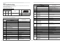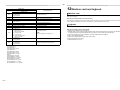
1
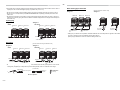
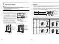
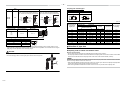
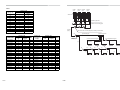
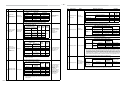
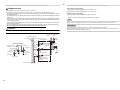
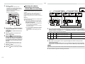
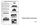
Specifications for communication wiring ◆ Design of communication wiring L1 L2 L3 N Circuit breaker (Earth leakage breaker) L1 L2 L3 N L1 L2 L3 N Summary of communication wiring L1 L2 L3 N Main switch (Fuse) Central control controller Header outdoor Follower outdoor U1 U2 U3 U4 U5 U6 U1 U2 U3 U4 U5 U6 U1 U2 U3 U4 Communication wiring between outdoor units (Shield wire) Communication wiring between indoor and outdoor units (Shield wire) Communication wiring between indoor units (Shield wire) U1 U2 A B U1 U2 A B Indoor unit Indoor unit Indoor unit A B Remote controller U1 U2 A B A B Remote controller U1 U2 A B Indoor unit A B Remote controller (Group control) • Communication wiring and central control wiring use 2-core non-polarity wires. Use 2-core shield wires to prevent noise trouble. In this case, both ends of the communication wire must be grounded. • Use 2-core non-polarity wire for remote controller. (A, B terminals) Use 2-core non-polarity wire for wiring of group control. (A, B terminals) 39-EN – 20 – 40-EN