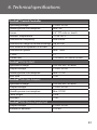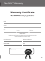
1
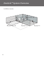
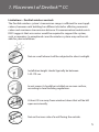
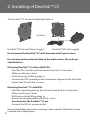
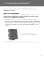
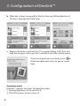
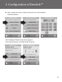
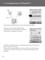
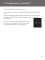
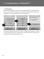
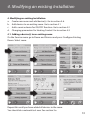
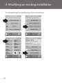
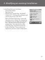
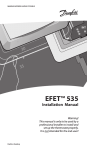
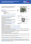
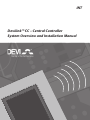
INT
Devilink™ CC – Central Controller
System Overview and Installation Manual
Index / Devilink™System Overview
Devilink™ System Overview....................................................................................
1.0 Placement of Devilink™ CC............................................................................
2.0 Mounting of Devilink™ CC..............................................................................
3.0 Configuration of Devilink™ ...........................................................................
4.0 Modifying an exiting Installation.................................................................
5.0 Troubleshooting................................................................................................
6.0 Technical specifications..................................................................................
Devi Warranty...............................................................................................................
Devilink™ is a wireless control system for electrical floor heating.
The central brain in the system is the Devilink™ CC (Central
Controller) equipped with a colour touch screen. From this
you can control the entire installation. The Devilink™ CC
communicates wirelessly with all other Devilink™ devices in
the installation.
If you want to operate on room temperature you have the option
of installing a Devilink™ RS (Room Sensor). This has a built-in
room sensor and thus measures the ambient temperature. You
can also adjust the temperature with Devilink™ RS
The Devilink™ RS (Room Sensor) has a built-in temperature
sensor which measures the ambient temperature. It allows
you to control the heating based on room temperature, in the
specific room where installed. With the Devilink™ RS you can also
adjust the temperature.
Devilink™ PR (Plug in relay) is a device supporting two types of
operation modes, either for controlling heating element or other
electrical equipments ON/OFF manually or by schedule.
2
2
5
6
7
13
20
23
26
Devilink™ System Overview
When using Devilink™ PR as heating regulation you also have
to install a Devilink™ RS, which allows you to control the
heating based on room temperature, in the specific room
where installed. With the Devilink™ RS you can also adjust the
temperature.
Devilink™ PR is to be put in to a socket/outlet together with a
SCHUCKO plug.
Devilink™ HR (Hidden relay) is a device supporting two types
of operation modes, either for controlling heating element or
other electrical equipments ON/OFF manually or by schedule.
When using Devilink™ HR as heating regulation you also
have to install a Devilink™ RS, which allows you to control
the heating based on room temperature, in the specific room
where installed. With the Devilink™ RS you can also adjust the
temperature.
Devilink™ HR is to be mounted in to a build in box in the wall.
Devilink™ FT (Floor Thermostat) or FTS (FT with sensor)
is one device supporting 3 types of operation modes, for
controlling of heating elements or other electrical equipments
ON/OFF manually or by schedule.
By controlling of floor heating DEVI always recommends
installing of a floor sensor.
Comfort heating – where a comfortable warm surface of the floor is
required you have only to connect a floor sensor to the Devilink™ FT as
heating regulation.
By Total heating you have to connect a floor sensor to the Devilink™ FT and
combined the installation with a Devilink™ RS, which allows you to control
the heat through both air and floor measurements. Devilink™ FT is to be
mounted in to a build in box in the wall or external box on the Wall.
3
Devilink™ System Overview
Installation scenario:
22.0
22.0
Devilink™ RS
ed
geriv
055™
devireg™550
Devilink™ HR or PR
4
Devilink™ CC
Devilink™ FT
1. Placement of Devilink™ CC
Limitations – Devilink wireless controls
The Devilink wireless system’s transmission range is sufficient for most applications; however each building has different obstacles affecting communication and maximum transmission distance. If communication trouble exists
DEVI suggests that accessories would be required to support the system,
such as repeaters. In exceptional cases the wireless system may not be suitable for your installation.
Not on a wall where it will be subjected to direct sunlight.
Installation height should typically be between
140-170 cm.
In wet rooms it should be installed on an even surface,
according to local building regulations.
At least 50 cm away from windows/doors that will be left
open occasionally.
Not on the inner side of a wall facing the outside.
5
2. Installing of Devilink™ CC
The Devilink™ CC can be installed with either a
or with a
Devilink™ PSU (in-wall Power Supply)
Devilink™ NSU (Net supply)
Do not power the Devilink™ CC until the manual tells you to do so.
Do not remove the protective film on the touch screen, the end user
should do this.
Mounting Devilink™ CC with In-Wall PSU:
• Hold the PSU over the wall box and mark up the 4 screw holes.
Make sure the top is level.
• Drill holes and put fitting plugs in.
• Connect the PSU according to the connection diagram on the back side.
• Mount the PSU with the 4 screws.
Mounting Devilink™ CC with NSU:
• Hold the mounting plate on the wall and mark up the 4 screw holes.
Make sure the top is level.
• Drill holes and put fitting plugs in.
• Mount the mounting plate with the 4 screws.
Do not mount the Devilink™ CC yet.
• Connect the NSU to a power outlet.
6
Now mount all the room units according to their manuals. When that is done
continue with Configuration.
3. Configuration of Devilink™
Start only at this point when all devices (FT, RS, HR and PR) have been
mounted in the rooms.
Adding devices to the system:
When you want to attach devices like FT, RS, HR, PR to your system the CC
must be within 1.5 meter from the device. To enable this, a battery pack,
Devilink™ BSU, is offered as an installer tool.
a.Put 10 fresh AA alkaline batteries in the BSU by sliding the lid off . Be
aware of the correct battery polarity. Slide the lid back on and attach the
Battery Pack BSU on to the back of the Devilink™ CC. When you are ready
to do the commissioning turn the switch located on the BSU to the ON
position.
Devilink™ BSU (Battery Supply Unit)
Devilink™ CC will now start up, this takes several minutes. Please be patient…
7
3. Configuration of Devilink™
b.When the system is powered for the first time you will be asked to set
Country, Language and Date/Time.
c.Remove the front cover from the CC by gently pulling it off. Press and
hold the setup pin with a pen for 3 seconds to start the installer menu.
If you are in doubt you can always press
in
the lower right hand corner to get on screen
help.
Operation mode
Devilink™ supports two types of operation modes.
1.Heating regulation. Go to section 3.d
2.ON/OFF function. Go to section 4.2
8
3. Configuration of Devilink™
d.Now create the rooms where the local units are installed.
Add New Room:
The Configure Room menu now appears.
Press Room Devices and then Add a Device
9
3. Configuration of Devilink™
Max 1.5 m
Repeat this step until all devices in the room have been added
When you have completed adding all the
devices for the room, you will get an overview
of the devices associated to the room.
Devilink™ automatically selects the regulation principle according to the
types of devices in the room.
If you want to change regulation, first read section 4.3 and then choose
Heating control. This is also where you set the maximum limit for your
floorings.
10
3. Configuration of Devilink™
Press back to get to the Configuration menu.
Now go back to the section 3.d. and repeat this for all rooms in the installation.
Now turn off the battery pack and place the Devilink™ CC on the mounting
plate that you installed earlier. It will now power up again and show you a
screen like this.
Now press the setup pin again to finalise the installation. You must now perform a Network test to ensure
that the wireless network is working properly.
11
3. Configuration of Devilink™
e. Network test
After ended installation or if you are uncertain about the network performance, you should do a network test. In the Service Menu, go to Status and
Diagnostics and choose Networks. Start network test.
At the end of the network test you will be informed that the test is waiting
for the Devilink™ RS units. You have to go to all the Devilink™ RS units only
and press the ON/OFF button for 5 sec.
12
4. Modifying an existing Installation
4. Modifying an existing Installation.
a. Create new room and add device(s). Go to section 3.d.
b. Add devices to an existing room. Go to section 4.1
c. Add a service device for ON/OFF function. Go to section 4.2
d. Changing parameters for Heating Control. Go to section 4.3
4.1. Adding a device(s) to an existing room:
On the Service menu go to Room and Devices and press Configure Existing
Room. Select room.
Repeat this until you have added all devices in the room.
You should do a network test now. See section 3.e.
13
4. Modifying an existing Installation
4.2 Adding a service device:
Service devices can be a PR, HR or FT used as a simple ON/OFF function.
You should do a network test now. See section 3.e.
NB! Heating elements which is connected to Devilink™ PR
have to be self protective against overheating.
14
4. Modifying an existing Installation
4.3 Changing parameters for Heat Regulation
Devilink™ offers 3 types of regulation, which can be set individually for each
room:
Floor heating
Comfort heating: Constant temperature on the floor in bathrooms and
other rooms where a comfortable warm surface is required. Install the floor
sensor with the Devilink™ FT and choose Floor regulation for the room
when doing the configuration.
Total heating: Control of room temperature in living rooms etc. Install the
floor sensor with the Devilink™ FT and a Devilink™ RS. Choose Combined
regulation when doing the configuration on the Devilink™ CC.
No floor sensor: DEVI recommends always installing a floor sensor.
Do not install floor heating system without a floor sensor when the
heating element is installed on or beneath wooden surfaces and other
surfaces sensitive to temperature!
Other types of heating:
It is recommendable to connect other types of heating elements to a PR, HR
or FT (without sensor) in combination with a RS.
15
4. Modifying an existing Installation
To change the type of regulation, go to the service menu.
16
4. Modifying an existing Installation
In Heat Regulation you can change:
• Forecasting method
• Regulation type
• Maximum floor temperature. The default
setting is 35°C. To change this setting you will need to enter the pin code: 0044.
Notice: The floor temperature is measured
where the sensor is placed. The temperature
at the floor sensor can differ many degrees
from that measured on the top of e.g. a
wooden floor. Floor manufactures often
specify the max. temperature on the top
surface of the floor. Please contact your
supplier for maximum surface temperature.
17
4. Modifying an existing Installation
4.4 Removing or Resetting a device
You can remove any local device from your Devilink™ system by resetting it.
Resetting a device:
Devilink™ FT: Turn off power on the safety switch on the front. Hold the
install button in while pushing ON the safety switch and keep the install
button pressed until the LED gives a red flash (approx. 5 sec.)
Devilink™ RS: Remove the front cover of the device. Take one battery out
and hold the
Installation (ON/OFF) button down while reinserting the battery. Continue
pressing the button down until the LED gives a red flash – approx. 5 sec.
Devilink™ PR: Cut of power by disconnecting the unit. Hold the Installation
button while reconnection of power establish. Continue pressing the button until the LED gives a red flash – approx. 5 sec.
Devilink™ HR: Remove the cover of the build in box. Press and hold both
light grey buttons in front of the device until the LED gives a red flash –
approx. 5 sec.
18
4. Modifying an existing Installation
Removing a device:
If you want to remove a dead device from your Devilink™ system, go to the
service menu by pressing the setup pin behind the front cover. Go to Room
and Devices and select Manage Devices. Select remove any device and do a
reset on the actual device.
If the device is broken, remove the device from the system by pressing
Remove dead device and then select the device to be removed. To add a
replacement device just follow process described in 4.1 Adding a device.
19
5. Trouble shooting
5.1 Warnings:
If an alert or warning occurs a yellow alert icon will be shown on the Standby
screen. Now press the red button, and then the View Alerts, to find more
information on the issue.
20
5. Trouble shooting
5.2 FAQ:
Regulation type: Q: Why can I not choose the regulation type that I
want?
A: Make sure the device configuration is correct, see
Heat Regulation section
If you need to add a floor sensor to your FT, you must
uninstall the FT. When you have mounted the sensor,
add the FT to the system once again.
Add Device:
Q: why can I not add a FT to a room?
A: If a FT is already included in a room, the sensor
configuration on the additional FTs must be the same.
There is a maximum of 4 FTs per room.
Q: Why can I not add an extra RS to a room?
A: There can maximum be one RS per room.
Q: Why can I not add an extra OS (Outdoor sensor)?
A: The system only supports one OS.
Replace device:
Q: I have a broken device. How do I replace it?
A: In the Service menu go to Manage Devices and
choose Replace Device.
21
5. Trouble shooting
Installer tool battery warning
Battery level Critical on device
Battery level low on device
Device not responding
Too many dead devices
Heating turned off in a room
Min. floor temperature limit
Tamper proof / Restrictions enabled
Manual operation
Icon for Floor Temperature
Icon for Room temperature
22
6. Technical specifications
Devilink™ Central Controller
Operating voltage
15 VDC ±10%
Standby power consumption
Max. 2W
Screen
3.5” TFT color w. touch
Ambient temperature
-10 to +35°C
Transmission frequency
868.42MHz
Transmission range in normal buildings Up to 30m
Max. number of repeaters in a chain
3
Transmission power
Max. 1 mW
IP class
21
Dimensions
125 mm x 107 mm x 25 mm
Devilink™ PSU (In-Wall)
Operation Voltage
100-250 VAC 50/60Hz
Output Voltage
15 VDC ±10%
Standby power consumption
Max. 0.15W
Max. load
10W
Devilink™ NSU (Net Adapter)
Operation Voltage
100-240 VAC 50/60Hz
Output Voltage
15 VDC ±10%
Standby power consumption
Max. 0.75W
Cable length.
2.5m
Max load
10W
Devilink™ BSU (Battery Supply Unit)
Output Voltage
15 VDC ±10%
Number of batteries
10 x AA
23
6.
specifications
6. Technical
Disposal Instruction
24
25
The 2 Year DEVI Warranty
You have purchased a DEVI heating
system which we are sure will serve to
improve the comfort and economy of
your application.
This warranty shall only be valid on
production of proof of purchase and
must be submitted to the installer or
seller without undue delay.
DEVI provides superior electrical heating
solutions for total climate control in
and around homes and buildings. DEVI
offers a complete product program with
Deviflex™ heating cables or Devimat™
heating mats, Devireg™ thermostats,
Devifast™ fixing strips and Devi Selflimiting heating cables combined with
additional products completing the
product program.
An extension of the warranty period
following repairs undertaken under
warranty cannot be granted.
This 2 year warranty applies to all DEVI
products.
Should you, against all expectations,
experience a problem with your DEVI
product, you will find that DEVI offers a 2
year warranty from the date of purchase
on the following conditions:
During the warranty period DEVI shall
offer a new comparable product or
repair the product in case the product is
found to be faulty by reason of defective
design, materials or workmanship.
Repair or re-placement shall be carried
out at DEVI’s discretion. DEVI shall
not be liable for any consequential or
incidental damages including, but not
limited to, damages to property or extra
utility expenses.
26
The DEVI Warranty shall not cover any
damage caused by incorrect conditions
of use, incorrect installation or if
installation has been carried out by
non-authorised electricians. All work will
be invoiced in full if DEVI is required to
inspect or repair faults that have arisen
as a result of any of the above.
The DEVI Warranty shall not extend to
equipment which has not been paid in
full.
DEVI will, at all times, provide a rapid
and effective response to all complaints
and inquiries from our customers.
The warranty explicitly excludes all
claims exceeding the above conditions.
The DEVI™ Warranty
Warranty Certificate
The DEVI™ Warranty is granted to:
Name:
Address
City:
Country:
Telephone:
Attention:
The Warranty Certificate must be completed correctly for the Warranty to be valid.
Please read the Warranty conditions above.
Type of thermostat:
Electrical installation by:
Article number:
Date:
Suppliers Stamp:
27
VICKA202
DEVI A/S
DK • 7100 Vejle
Phone +45 7488 8500
Fax +45 7488 8501
08/2009
Article no: 08095908
Version: 02.01