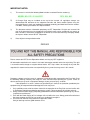
1
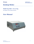
EasyClub
USER MANUAL
Induction Heating System For Manufacture
and Repair of Golf Clubs
Document No. 9USR-745-110-00 Rev. A01
IMPORTANT NOTES:
1)
This manual is valid for the following Model and the associated Revision number(s):
MODEL NO: EC-1.2/180A-PFC
REV. NO: A00
2)
A Change Page may be included at the end of the manual. All applicable changes are
documented with reference to the equipment Revision and Serial number. Before using this
Instruction Manual, check your equipment nameplate to identify your Model and Revision number.
If in doubt, contact your nearest UPT Representative.
3)
This document contains information proprietary to UPT Corporation. All rights are reserved. No
part of this document may be reproduced, transmitted, processed or recorded by any means or
form, electronic, mechanical, photographic or otherwise, nor be released to any third party without
the express written consent of UPT Corporation.
4)
Data subject to change without notice.
PREFACE
Please, contact the UPT Service Department before servicing any UPT equipment.
All Information contained in this manual is the latest information available at the time of printing. The right
is reserved to make changes at anytime without notice. UPT Corp. makes no warranty of any kind with
regard to this material and assumes no responsibility for any errors that may occur in this manual.
Dangerous voltages may be present in equipment surrounding and/or connected to the EasyClub. Read
the following warnings carefully and study this entire manual before operating the system. Failure to
observe warnings may result in equipment damage, serious personal injury, or death.
If the equipment is used in a manner not specified by this manual, the protection provided by the
equipment may be compromised and damage to the unit may occur.
1
2
3
4
Only qualified persons who have been trained in the operation of the EasyClub and are familiar with
its technology should be permitted to operate the system. Failure to comply will void the warranty..
Always have the Power Supply completely powered off and locked out before performing any service,
inspection or maintenance.
Even with the Power Supply off, live voltages still exist within the case. Always power off and lock out
the external power source to ensure no one can accidentally energize it.
Ensure that all external wiring conforms to applicable codes.
Obey all warnings and use good common sense.
2
TABLE OF CONTENTS
SECTION 1 - SAFETY INSTRUCTIONS ________________________________________ 5
1.1. INSTALLATION, OPERATION AND SERVICE PRECAUTIONS____________________ 5
1.2. GROUNDING ________________________________________________________________ 5
1.3. ELECTRICAL SHOCK HAZARDS ______________________________________________ 5
SECTION 2 – INTRODUCTION _______________________________________________ 6
2.1 MANUAL ORGANIZATION ____________________________________________________ 6
SECTION 3 - MANUFACTURER INFORMATION________________________________ 7
3.1 MANUFACTURING AND SERVICE _____________________________________________ 7
SECTION 4 – DESCRIPTION _________________________________________________ 7
4.1 OVERVIEW __________________________________________________________________ 7
4.2 SPECIFICATIONS ____________________________________________________________ 7
4.3 MECHANICAL SPECIFICATIONS ______________________________________________ 8
4.4 ENCLOSURE ________________________________________________________________ 8
4.5 FEATURES __________________________________________________________________ 8
4.5.1 CONTROL________________________________________________________________________8
4.5.2 PROTECTION ____________________________________________________________________8
4.6 ACCESSORIES ______________________________________________________________ 8
SECTION 5 – INSTALLATION _______________________________________________ 10
5.1 INSTALLATION PROCEDURE ________________________________________________ 10
5.2 UNPACKING AND INSPECTION ______________________________________________ 10
5.3 SELECTING THE POWER SUPPLY SITE ______________________________________ 10
5.4 COOLING___________________________________________________________________ 10
5.5 A-C INPUT CONNECTION ____________________________________________________ 10
SECTION 6 – OPERATION __________________________________________________ 12
6.1 CONTROL PANEL OVERVIEW________________________________________________ 12
6.1.1 MENU___________________________________________________________________________12
6.1.2 HOW DOES IT WORK, AND WHAT THE USER SHOULD KNOW? _____________________14
6.1.3 STARTING THE SYSTEM _________________________________________________________14
6.2 ALARMS, FAULTS AND WARNINGS __________________________________________ 16
6.2.1 PHASE FAULT___________________________________________________________________16
6.2.2 CURRENT FAULT ________________________________________________________________16
6.2.3 FREQUENCY FAULT _____________________________________________________________16
6.2.4 TEMPERATURE FAULT __________________________________________________________16
6.2.5 AUTO TUNE FAILED _____________________________________________________________16
6.2.6 COMMUNICATION FAULT ________________________________________________________16
.6.2.7 INDUCTOR HEAD MISSING ______________________________________________________17
6.2.8 POWER OVERLOAD _____________________________________________________________17
6.2.9 POWER SUPPLY FAULT _________________________________________________________17
SECTION 7 - MAINTENANCE _______________________________________________ 18
7.1 SCHEDULING _______________________________________________________________ 18
3
7.2 PERSONNEL________________________________________________________________ 18
7.3 INSPECTION AND MAINTENANCE PROCEDURE ______________________________ 18
7.3.1 DAILY AND WEEKLY INSPECTION ________________________________________________18
7.3.2 MONTHLY INSPECTION __________________________________________________________18
SECTION 8 – SERVICE _____________________________________________________ 19
8.1 GENERAL __________________________________________________________________ 19
8.2 SERVICE CONTACT INFORMATION __________________________________________ 19
8.3 SPARE PARTS LIST _________________________________________________________ 19
8.4 FUSE REPLACEMENT _______________________________________________________ 19
4
SECTION 1 - SAFETY INSTRUCTIONS
1.1. INSTALLATION, OPERATION AND SERVICE PRECAUTIONS
Hazardous voltages are present within this product during normal operation. The product should never be
operated with the cover removed unless equivalent protection of the operator from accidental contact with
hazardous internal voltages is provided.
There are no operator serviceable parts or adjustments within the product enclosure.
1.2. GROUNDING
This product is a Class 1 device which utilizes protective earthing to ensure operator‘s safety.
1.3. ELECTRICAL SHOCK HAZARDS
This product outputs hazardous voltage and energy levels as a function of normal operation. Operators
must be trained in its use and exercise caution as well as common sense during use to prevent
accidental shock.
This symbol appears adjacent to any external terminals at which hazardous voltage
levels as high as 500V D-C may exist in the course of normal or single fault conditions.
Source power must be removed from the product prior to performing any servicing
5
SECTION 2 – INTRODUCTION
This manual is written for personnel familiar with the technology pertaining to the operation of induction
heating equipment. Such personnel should be thoroughly familiar with the hazards associated with this
equipment and electrical equipment in general, and they should have received proper safety procedure
training.
2.1 MANUAL ORGANIZATION
Section 1:
Safety Instructions
Discusses hazards and safety precautions.
Section 2:
Introduction
Identifies the purpose and organization of this
manual.
Section 3:
Manufacturer Information
Contains information about the manufacturer
and its sales and service representatives.
Section 4:
Description
Specifies electrically and mechanically the
system.
Section 5:
Installation
Provides installation procedures.
Section 6:
Operation
Explains how to set different parameters and
how to use the inductor head. This section also
gives explanation for the whole.
Section 7:
Maintenance
Provides instructions for periodic inspection
and maintenance.
Section 8:
Service
Explains the service procedures and provides
manufacturer contact information.
The manual also uses WARNING and CAUTION.
A WARNING symbol alerts you to a hazard that may result in equipment damage, personal injury,
or death. Carefully read the instructions provided WARNING and follow all safety precautions.
A CAUTION symbol alerts you that the system may not operate as expected if instructions are not
followed.
Extra user information is provided in the text following this sign.
SECTION 3 - MANUFACTURER INFORMATION
3.1 MANUFACTURING AND SERVICE
ULTRAFLEX POWER TECHNOLOGIES
154-1 Remington Blvd
Ronkonkoma, NY 11779
Tel 631-467-6814
Fax 631-980-4065
SECTION 4 – DESCRIPTION
4.1 OVERVIEW
The UPT EasyClub is a unit designed to work in conjunction with inductor head designed exclusively for
it. The unit is digitally controlled through a membrane keypad located on the front panel. The Power
Supply is enclosed in a compact case. ON/OFF switch is installed on the back side of the enclosure to
power up and down the unit. Waterproof connectors are interfacing the power supply with the inductor
head and the foot switch. The power level is automatically adjusted depending on the actual value of the
load. The unit is equipped with Power Factor Corrected (PFC) front end module to meet the CE mark,
thus optimizing the line current utilization and reducing power bill cost.
Note:
1) A tool is required to gain access to the Power Supply. This is to prevent
accidental exposure to the internal high voltages.
2) See section ACCESSORIES for optional equipment.
4.2 SPECIFICATIONS
The PFC EasyClub system‘s electrical and mechanical specifications are listed in Table 1.
MAIN FEATURES
Size:
7" wide x 12" high x 9.5" deep (180 x 300 x 240 mm)
Weight:
14 lb (6.4 kg)
Max operating ambient
97°F (36°C)
temperature:
Universal Input line voltage:
110 - 230 Volts AC, 50/60 Hz, single phase
Max output power rating:
1.2 kW
Nominal output frequency:
50 -200 kHz
Thermal protection
Built in thermal protection with automatic fan control
CONTROL PANEL AND USER FEATURES
Displays, LED’s
“Heat-On” , Alarm, Time and Power status lights, 3digit,
7segment LED
Timer control:
0.2 - 9.9 sec. 0.1sec/step (10 - 60 sec. 1 sec/step)
Power regulator step:
Power control: 10 - 120% PWM (1% step)
OTHER FEATURES
End of cycle and Fault audible signal
Heat On indicating LED on the back side of the inductor head
Power monitoring and automatic power limiting capability
Dry flexible lead connects the power supply to the inductor head
Table 1: Specifications
4.3 MECHANICAL SPECIFICATIONS
Fig. 2: Mechanical Outline Drawing. All dimensions stated as follows: mm (inch)
4.4 ENCLOSURE
The enclosure has been designed with NEMA 2 and IP 21 standards in mind.
4.5 FEATURES
4.5.1 CONTROL
Control of the EasyClub Power Supply is done via a local panel integrated in the unit enclosure. 4-wire
bus secures the power supply of the panel as well as the RS-485 connectivity. The panel has user
friendly interface with 3 digit LED display and membrane keypad based on a digital state of the art
microprocessor technology. Individual status LED’s are placed for indicating the mode of operation. On
board audible alarm helps easier detecting of fault and unstable operating conditions. A simple
multifunction 5-button membrane keypad secures easy programming in real time mode as well as
retrieving user preset programs. Remote control is also available through a supplied footswitch. (For more
details see section 4.6 Accessories).
4.5.2 PROTECTION
1
2
3
4
Overpower protection: Tracks output power; activated if the output goes out of tolerance
Over current protection: Tracks output current; activated if the output goes out of tolerance
Input Over current protection: Tracks input current; activated if the input goes out of tolerance
Over temperature: Activated when the internal temperature exceeds a safe operating threshold
4.6 ACCESSORIES
The following accessories are available for system enhancement and customization.
ACCESSORY
Foot Switch
Ultraflex P/N
1ACC-737-500-00
8
Power Cord (US style NEMA 5-15) 8ft.
Inductor Head
4KAB-000-018-00
1ACC-745-100-00
Table 2: Accessories
9
SECTION 5 – INSTALLATION
5.1 INSTALLATION PROCEDURE
The installation procedure consists of the following steps:
1.
2
3
4
5
Unpacking the equipment.
Selecting the site where the equipment will be used.
Connecting the inductor head to the Power Supply.
Connecting the foot switch (if necessary).
Completing the power and Ground/Earth connections.
Power and ground/earth connections must be made last. Failure to do so will
create a hazardous condition that may result in equipment damage, personal
injury, or death.
NOTE: UPT Corporation has a staff of field engineers that is available to supervise
the installation of the equipment. If installation service is required, contact the UPT
Technical Service Department for additional information.
Provisions for facility electrical power service are customer furnished. Requesting
UPT field engineering assistance before customer furnished provisions are
installed at the equipment site could delay equipment installation and cause
unnecessary expense.
5.2 UNPACKING AND INSPECTION
This equipment has been thoroughly inspected and tested prior to packing and is ready for operation.
After careful unpacking, visually inspect for shipping damage before attempting to operate. If any
indication of damage is found, file an immediate claim with the responsible transport service and advise
your UPT representative.
WARNING
Inspect equipment before installing. Damaged equipment may result in improper
operation and create a hazardous condition resulting in personal injury or death.
The carrier is responsible for all damage caused in shipment including concealed
damage.
5.3 SELECTING THE POWER SUPPLY SITE
Consider the following when choosing a location for the Power Supply.
1 Make sure the unit is installed in a debris free zone.
2 The Power Supply has to be connected to a power source.
3 The Power Supply has to be in a location to allow an attached inductor head to reach the
workplace.
4 Make sure the unit is easily accessible by the operator.
5 The Power Supply has to be seated on a mechanically secure surface.
5.4 COOLING
The power transistors and rectifiers in the EasyClub Power Module are maintained within their safe
operating temperature range by means of forced cooling by 120x120mm fan. For this reason the fan inlet
must be kept clean from obstructions in order to insure proper air circulation. If installed in confined
spaces, care must be taken that the ambient temperature (the temperature immediately surrounding the
Unit does not rise above the limit specified 98˚F (37 deg. C). Periodic cleaning of the Unit exterior is
recommended.
5.5 A-C INPUT CONNECTION
The EasyClub connects to the power network through 8 ft. NEMA 5-15 power cord (supplied). If you are
using this equipment in a country other than USA, please supply proper power cord compatible with your
power network outlet. A list of available power cords is shown in Table 2.
Note: If you supply a cable cord on your own, please make sure it is rated 15A and above.
The unit has a built in fuse protection on each line rated at 20A. With its allowable 95-245 VAC input, it
could see a maximum current of 13A a-c. It is highly recommended that the unit is connected to a
separate protected power branch on the in-house power network. 16A fuse or circuit breaker on that
power branch is a good choice since it will trip before and instead of the internal protection. A mechanical
30 A switch is also recommended within the operator‘s range and vision and possibly closer to the Power
Supply. (See Fig. 2 for details).
Fig.2: Power Line Connection
NOTE: Local codes may have stringent requirements. It is the customer‘s responsibility to be
familiar with and to comply with all applicable codes concerning conductor ratings and wiring
procedures. An electrician familiar with the local regulations should determine proper wiring
connections. The energy unit can operate on an input voltage of 95-245 VAC.
11
SECTION 6 – OPERATION
6.1 CONTROL PANEL OVERVIEW
The main design objective of the Control Panel is easy access to all the operational and
setting functions of the EasyClub power supply, as well as displaying device state data to the user in
ergonomic manner.
The panel is situated on the upper front side of the power supply case. It has five control
buttons, indicator LED's and a 3 digit LED display. They are situated as follows:
Fig.3 -Control Panel Layout
6.1.1 MENU
The menu structure is simple, but very useful as well. It‘s structure is shown in a flowchart (Fig. 4a & 4b).
After powering the device on, the control panel software revision is displayed for a period of 2 seconds
(See user menu structure -Fig.4b). Then the unit enters in power setting mode which allows setting the
power output by pressing the Up/Down buttons. Confirmation of the setting is done by pressing the Select
button. Then the duration of the “Heat-On“ cycle might be set. Up/Down buttons are altering cycle
duration (in seconds). At this point the unit might be started with all the parameters set.
Pressing the select button when in “Heat-On“ mode toggles display of both the parameters of power and
duration. Holding the Select button for more than 3 seconds brings the user to the system menu (Fig.4b).
The system menu features that could be of use to the EasyClub operator are the Control Panel (CP) and
Control Board (CB) version check menus. There the system software versions info could be obtained,
which is useful when contacting UPT Service Department. When in system menu, the user may toggle
between the items using the Up/Down buttons. Selecting and Exiting an item is done by pressing the
Select button. The user may exit the system menu by toggling to the “End“ item and then pressing Select
to confirm going back to the user menu.
Fig. 4a – User Menu structure
13
Fig.4b -System menu structure
6.1.2 HOW DOES IT WORK, AND WHAT THE USER SHOULD KNOW?
The device described in this manual is intended for production and repair of golf clubs in
industrial as well as in small workshop environment. The device works by applying alternating magnetic
field to the hosel. The magnetic field induces electric current inside the material which has certain
resistance, therefore the area exposed to the inductor head heats up.
After performing all the installation steps in the manual Ch.5 you are ready to work with the
EasyClub.
Despite that the device is quite easy to operate, the operator should at all times abide by
the precautions and safety measures specified in this document. Avoid contact with
heated parts of the golf club due to burn injury hazard.
When using the device be aware that the head and shaft are becoming hot and clamps or some
additional gear might be needed in order to pull the club head off.
6.1.3 STARTING THE SYSTEM
NOTE: Before proceeding, complete all the required electrical connections.
1. Attach the inductor head cable to the Power Supply using the 10-pin connector located
on the front side of the unit.
14
2. Make sure the Power supply is properly wired and that power to the unit is available.
3. Turn the ON/OFF switch on the back of the Power Supply to the ON or “1“ position to
turn it on. As mentioned in 6.1.1 After turning the device ON it displays the software
version number and enters in power setting mode (See user menu structure -Fig.4b).
Set the timer and power output according the club hosel size and the heat amount you
want to reach. Take the inductor head and position it over the hosel so that it covers
the place that has to be heated (Fig.5). The deeper the hosel gets into the inductor gap
the better it‘s heated.
Fig.5 Inductor head alignment
With the timer and power output already set, EasyClub is ready to be started, by pressing the
footswitch or the front panel‘s start button. The “HEAT ON“LED is lit and the timer counts down to zero,
after which the unit stops and HEAT ON“ LED goes off. If the power is set for 100% or less it may be
immediately restarted. The minimum “HEAT ON“ time is 0.2sec. The output power can be set between
the limits of 10% and 120%.
If the power is set between 100% and 120%, the unit will automatically turn itself off in 5 seconds. It will
not allow to be restarted for another 5 seconds.
The time can be set for up to 5.0 sec. As the set power output raises, the pause duration needed between
“HEAT ON“ cycles increases, leaving the unit to cool down. (Example: for 120% power output and time
5.0 sec.-after one "HEAT ON" cycle there must be at least a 5.0 sec pause, while for 110% power output
and ON time of 5 sec. the power supply must rest for at least 2.5 sec).
15
6.2 ALARMS, FAULTS AND WARNINGS
The following are possible alarms, faults and warnings that the customer may encounter.
6.2.1 PHASE FAULT
The primary current and voltage of the Power Supply are set —“in phase“ at the factory. This subjects the
semiconductor devices to the least amount of stress and reduces heat build up and extends the life of the
devices. This fault results when the current and voltage fall out of phase enough to possibly cause
damage to the devices. Continued occurrence of this fault could be an indication of Power Supply failure.
Contact UPT Service Department.
6.2.2 CURRENT FAULT
As a safety feature, the current that runs through the main output circuitry supplying energy to the
inductor head is monitored. If that current exceeds a preset limit, a current fault condition will occur. This
fault can be indicative of a bad semi-conductor device or a possible short in the wiring. Contact UPT
Service Department.
6.2.3 FREQUENCY FAULT
The Power Supply is programmed to run within a certain frequency range. When the unit attempts to run
outside the proper frequency range, a frequency fault is realized. A couple of reasons for this could be a
drastic change in the inductance of the attached coil or possibly a capacitor that has gone bad. Contact
UPT Service Department.
6.2.4 TEMPERATURE FAULT
Making use of the temperature sensor within the MOSFET device and some external circuitry, should the
MOSFET device get too hot, the unit will stop running and produce this fault. Allow the unit to cool before
trying to run it again. If the fault keeps occurring, make sure the fan is working properly and that none of
the vents allowing air to flow through the unit are blocked. If everything checks out well, contact UPT
Service Department.
6.2.5 AUTO TUNE FAILED
This message is displayed if the unit fails in automatic recognition of inductor head. Please turn the unit
off, wait for few seconds until all the panel lights go off and then reconnect the inductor head. Turn the
unit on and try running it again. If there is no positive result, contact UPT Service Department.
6.2.6 COMMUNICATION FAULT
The Control Panel and the Control Board inside the unit, have microprocessors, which need to
communicate with each other to work properly. This fault occurs if there is a loss of communications
between these two microprocessors. An unplugged due to a mechanical shock internal cable, broken wire
or weak contact might be the reason for such a fault. If the error occurs frequently or the unit fails to start
at all, contact UPT Service Department.
16
.6.2.7 INDUCTOR HEAD MISSING
The message above indicates that the inductor head is disconnected from the power supply. Check for
loose connection between them and then restart. If the error keeps occurring, unplug the unit off the
mains socket and inspect connector for traces of dirt or other obstacles that might prevent electrical
contact. If this doesn‘t help, contact UPT Service Department.
6.2.8 POWER OVERLOAD
This message is shown when the output voltage reaches unsafe limit because the unit got overloaded.
Use this device only for golf club repairing or assembly. If this error occurs while no load is present, or at
normal loading conditions, contact UPT Service Department.
6.2.9 POWER SUPPLY FAULT
This message will be displayed when the PFC module fails or when a general fault in the Power Supply occurs. Turn
the unit off for about 30 seconds and then try turning it on after making an inspection of cables, connections and
sealing head state. If the error persists, contact UPT Service Department.
17
SECTION 7 - MAINTENANCE
7.1 SCHEDULING
The UPT Power Supply is designed for continuous service and minimum maintenance requirements. The
frequency of any maintenance program is a function of environment, degree of equipment use, and
product experience.
7.2 PERSONNEL
Qualified personnel must perform inspection and maintenance procedures only. Personnel must read and
be thoroughly familiar with all safety precautions discussed in this manual.
7.3 INSPECTION AND MAINTENANCE PROCEDURE
Note: Always follow approved lockout / tag out procedures before performing any service,
inspection or maintenance.
The following describes inspection procedures to be performed on a daily, weekly, and monthly basis.
7.3.1 DAILY AND WEEKLY INSPECTION
It is good practice to do a quick visual inspection of the unit, wiring and connections on a daily and/or
weekly basis. Report any apparent changes in performance to responsible personnel so that potential
problems can be investigated.
7.3.2 MONTHLY INSPECTION
Perform the following on a monthly basis:
1. Ensure all wiring connections are secure. Visually inspect for any wear on cabling.
2. Verify that none of the enclosure hardware has become loose.
3. Remove any build-up debris that may occur around the fan inlet using a cloth or a vacuum
cleaner. Use of compressed air is not recommended.
4. Wipe the Control Panel with a damp cloth to remove any dirt, prints or smudges.
5. Wipe the enclosure down with a damp cloth or using stainless steel cleaner, if desired.
SECTION 8 – SERVICE
8.1 GENERAL
There are no user serviceable parts inside the EasyClub unit. If for some reason the unit fails in the field it
is advisable that the unit be serviced by the manufacturer or its authorized service representative. Should
that happen, please contact us immediately. See Par. 8.2 for Service Contact Information. Please have
the following information about your unit available upon calling:
1 Unit Serial and Revision Number. See label in Section 4 for these numbers identification.
2 Line Voltage and frequency.
3 Date of Delivery
4 Detailed description of the problem encountered.
5 Detailed description of the actions taken.
6 Approximate time in service.
If our technical staff is unable to help you over the phone, then a return authorization number (RA#) will
be issued for you. With this number enclosed in you return package you can ship the unit back for repair.
See Par. 8.3 for Service Shipping Information.
Note: No unit should be sent back for service without valid RA #.
8.2 SERVICE CONTACT INFORMATION
For technical service questions, please call:
631-467-6814
You may also fax your questions or request at:
(631) 980-4065
Note: Please, include you contact information so that you can be easily reached if necessary.
8.3 SPARE PARTS LIST
Recommended spare parts for this unit are listed in table 3.
Item
Ultraflex PN:
Fuse
3FFT-000-016-00
Line Cord
4KAB-000-018-00
Table 3: Spare Parts List
UPT Corporation maintains a stock of replacement parts that are available upon request. Contact UPT
Corporation for further information on obtaining replacement parts.
8.4 FUSE REPLACEMENT
There are two fuses, one for each line on the PFC EasyClub Power Supply. They are located on the
backside of the unit in plastic screwable holders.
Power down and unplug the unit before replacing the fuse. Failure to do so will
create a hazardous condition that may result in equipment damage, personal
injury, or death.
- Unscrew the plastic holder with flat screwdriver to gain access to the fuse.
Note1: Replace a burnt fuse only with the same type of fuse. It is recommended
that a factory certified fuse is used for replacement. For fuse ordering information,
please see Par. 6.4 Note 2: Do not overrate the fuse. That is fire hazardous and may
cause personal injury or death. Make sure the fuse you are installing is rated
20A/250V.
- Put a new fuse in the fuse holder and screw it back to the unit. Secure the fuse screw by applying
adequate screw torque.
Loose fuse screw may cause local overheating, unit damage or fire. If the fuse fails
second time immediately or short after been replaced, please contact the factory
prior taking any other actions.
20