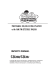
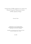
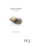
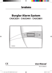
1
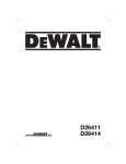
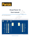
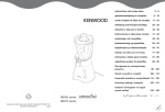
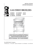
User Guide for FEBFSQ500L_H257v1 Evaluation Board Compact, Green-Mode Controller FSQ500L 5.1 V / 400 mA Flyback Design Featured Fairchild Product: FSQ500L Direct questions or comments about this evaluation board to: “Worldwide Direct Support” Fairchild Semiconductor.com © 2011 Fairchild Semiconductor Corporation 1 FEBFSQ500L_H257v1 • Rev. 1.0.2 Table of Contents 1. Introduction ............................................................................................................................... 3 1.1. General Description ........................................................................................................... 3 1.2. Features .............................................................................................................................. 3 2. Specifications ............................................................................................................................ 4 3. Photographs & PCB Layout...................................................................................................... 5 4. Function Test Report................................................................................................................. 6 4.1. Input Current ...................................................................................................................... 6 4.2. Input Wattage at No-Load Condition ................................................................................ 7 4.3. Burst Mode Test ................................................................................................................. 7 4.4. Soft-Start Test .................................................................................................................... 8 4.5. Turn-On Delay Test ........................................................................................................... 9 4.6. DC Output Rising Time ..................................................................................................... 9 4.7. Line and Load Regulation ................................................................................................ 10 4.8. Efficiency ......................................................................................................................... 11 4.9. Output Ripple and Noise.................................................................................................. 11 4.10. Step Load Response ....................................................................................................... 12 4.11. Over-Current Protection................................................................................................. 13 4.12. Hold-up Time ................................................................................................................. 13 4.13. Short Circuit Protection ................................................................................................. 14 4.14. Maximum Duty Ratio .................................................................................................... 15 4.15. Power Off ....................................................................................................................... 15 4.16. Over-Temperature Protection (OTP) ............................................................................. 15 4.17. Voltage Stress of Drain and Secondary Rectifier .......................................................... 16 4.18. EMI Waveforms............................................................................................................. 17 4.19. Surge Test ...................................................................................................................... 18 4.20. ESD Test ........................................................................................................................ 18 5. Schematic ................................................................................................................................ 19 6. Transformer Specification ...................................................................................................... 20 7. Bill of Materials ...................................................................................................................... 23 8. Revision History ..................................................................................................................... 24 © 2011 Fairchild Semiconductor Corporation 2 FEBFSQ500L_H257v1 • Rev. 1.0.2 This user guide supports the evaluation kit for the FSQ500L. It should be used in conjunction with the FSQ500L datasheet as well as Fairchild’s application notes and technical support team. Please visit Fairchild’s website at www.fairchildsemi.com. 1. Introduction This engineering report describes a 2.04 W power supply using a FSQ500L. This power supply is targeted for a flyback converter replaces linear power supplies with low cost and small size. 1.1. General Description This device combines a current-mode Pulse Width Modulator (PWM) with a SenseFET and high-voltage regulator connected from the DRAIN pin to supply the VCC. This device does not need to use bias winding and associated external components. Using a SOT-223 package, FSQ500L reduces total size and weight while increasing efficiency, productivity, and system reliability. Using FSQ500L, this design example for 2.04 W can be implemented with few external components and minimized cost. 1.2. Features Single-Chip 700 V SenseFET Power Switch Precision Fixed Operating Frequency: 130 kHz No-load consumption 250 mW at 265 VAC with Burst Mode and Down to 60 mW with External Bias Internal Startup Switch Soft-Start Time Tuned by External Capacitor Under-Voltage Lockout (UVLO) with Hysteresis Pulse-by-Pulse Current Limit Overload Protection (OLP) and Internal Thermal Shutdown Function (TSD) with Hysteresis Auto-Restart Mode No Need for Auxiliary Bias Winding © 2011 Fairchild Semiconductor Corporation 3 FEBFSQ500L_H257v1 • Rev. 1.0.2 VCC D 2 1 6.5V Soft-Soft VCC VCC I FB IIDELAY 7.7VZ OSC (BURST MODE:IFB/2) VFB 3 S 8R VREF UVLO Q R R HV/REG 250ns LEB RSENSE V BURL/V BURH (0.3V) HV/REG OFF S Q A/R OLP R TSD VSD 4 GND Figure 1. Internal Block Diagram 2. Specifications Table 1. Summary of Features and Performance Description Min. Max. Unit Voltage 90 264 VAC Frequency 47 63 Hz 5.1 V 0 0.4 A 0 2.04 W Input Output Output Voltage 1 Output Current 1 Total Output Power Full-load Output Power Peak Output Power © 2011 Fairchild Semiconductor Corporation W 4 FEBFSQ500L_H257v1 • Rev. 1.0.2 3. Photographs & PCB Layout Figure 2. Top Overlay Silk Screen Figure 3. Figure 4. © 2011 Fairchild Semiconductor Corporation Bottom Layer Pattern Bottom Overlay Silk Screen 5 FEBFSQ500L_H257v1 • Rev. 1.0.2 4. Function Test Report Test Model Test Date Test Temperature Test Equipment Test Items FEBFSQ500L_H257v1 June.23, 2008 Ambient AC source: 6800 AC POWER SOURCE Electronic load: Chroma 63030 Power meter: WT210 Oscilloscope: LeCory 24Xs 1 2 3 4 5 6 7 8 9 10 11 12 13 14 15 16 17 18 19 20 Input Current Input Wattage at No-Load Condition Burst Mode Test Soft-Start Test Turn-On Delay Test DC Output Rising Time Line and Load Regulation Efficiency Output Ripple and Noise Step Load Response Over-Current Protection Hold-Up Time Short Circuit Protection Maximum Duty Ratio Power Off Over-Temperature Protection (OTP) Voltage Stress of Drain and Secondary Rectifier EMI Waveforms Surge Test ESD Test 4.1. Input Current 4.1.1. Test Condition Measure the AC input current at maximum loading. Table 2. Test Result © 2011 Fairchild Semiconductor Corporation Input Voltage Input Current 85 VAC / 60 Hz 57.62 mA 264 VAC / 50 Hz 35.73 mA 6 FEBFSQ500L_H257v1 • Rev. 1.0.2 4.2. Input Wattage at No-Load Condition 4.2.1. Test Condition Measure the input wattage and output voltage at no load. Table 3. Test Result Input Voltage Input Wattage Output Voltage 85 VAC / 60 Hz 0.094 W 5.224 V 120 VAC / 60 Hz 0.116 W 5.224 V 230 VAC / 50 Hz 0.209 W 5.224 V 264 VAC / 50 Hz 0.242 W 5.224 V Specification < 0.25 W 4.3. Burst Mode Test 4.3.1. Test Condition Measure the waveform and frequency in Burst Mode at no load. Ch1 Ch2 Ch1 Ch2 Ch3 Ch3 Figure 6. 264 VAC / 50 Hz at No Load (Ch 1: Vo, Ch 2: VDS, Ch 3: VFB) Figure 5. 85 VAC / 60 Hz at No Load (Ch 1: Vo, Ch 2: VDS, Ch 3: VFB) © 2011 Fairchild Semiconductor Corporation 7 FEBFSQ500L_H257v1 • Rev. 1.0.2 4.4. Soft-Start Test 4.4.1. Test Condition Measure the soft-start waveform at maximum load with ambient, after short, after OTP. Table 4. Test Result Input Voltage Soft-Start Time 120 VAC / 60 Hz 14 ms Under 240 VAC / 50 Hz 14 ms Under Ch1 Ch3 Ch3 Ch1 Ch4 Ch4 Ch2 Ch2 Figure 7. 120 VAC / 60 Hz at Max. Load, Ambient (Ch 1: VO, Ch 2: VFB, Ch 3: VCC, Ch 4: IDRAIN) Figure 8. Ch3 240 VAC / 50 Hz at Max. Load, Ambient (Ch 1: VO, Ch 2: VFB, Ch 3: VCC, Ch 4: IDRAIN) Ch3 Ch2 Ch4 Ch4 Ch1 Ch1 Figure 9. 120 VAC / 60 Hz at Max. Load, After Short (Ch 1: VO, Ch 2: VFB, Ch 3: VCC, Ch 4: IDRAIN) Ch3 Figure 10. 240 VAC / 50 Hz at Max. Load, After Short (Ch 1: VO, Ch 2: VFB, Ch 3: VCC, Ch 4: IDRAIN) Ch1 Ch3 Ch1 Ch2 Ch2 Ch4 Ch4 Figure 12. 240 VAC / 50 Hz at Max. Load, After OTP (Ch 1: VO, Ch 2: VFB, Ch 3: VCC, Ch 4: IDRAIN) Figure 11. 120 VAC / 60 Hz at Max. Load, After OTP (Ch 1: VO, Ch 2: VFB, Ch 3: VCC, Ch 4: IDRAIN) © 2011 Fairchild Semiconductor Corporation Ch2 8 FEBFSQ500L_H257v1 • Rev. 1.0.2 4.5. Turn-On Delay Test 4.5.1. Test Condition Set the output at maximum loading. Measure the interval between AC plug-in and stable output. Table 5. Test Result Input Voltage Maximum Load 85 VAC / 60 Hz 89.60 ms 264 VAC / 50 Hz 99.08 ms Ch4 Ch4 Ch1 Figure 13. Ch1 85 VAC / 60 Hz at Max. Load (Ch 1: VO, Ch 4: VAC) Figure 14. 264 VAC / 50 Hz at Max. Load (Ch 1: VO, Ch 4: VAC) 4.6. DC Output Rising Time 4.6.1. Test Condition Set output at maximum loading and no loading. Measure the time interval between 10% and 90% of output voltage during startup. Table 6. Test Result Input Voltage Maximum Load No Load 85 VAC / 60 Hz 5.26 ms 4.04 ms 264 VAC / 50 Hz 5.05 ms 3.63 ms © 2011 Fairchild Semiconductor Corporation 9 Specification < 20 ms FEBFSQ500L_H257v1 • Rev. 1.0.2 Ch1 Ch1 Ch2 Ch3 Ch2 Ch3 Figure 15. Figure 16. 85 VAC / 60 Hz at Max. Load (Ch 1: VO, Ch 2: VDS, Ch 3: VFB) 85 VAC / 60 Hz at No Load (Ch 1: VO, Ch 2: VDS, Ch 3: VFB) Ch1 Ch3 Ch2 Ch1 Ch2 Ch3 Figure 17. Figure 18. 264 VAC / 50 Hz at Max. Load (Ch 1: VO, Ch 2: VDS, Ch 3: VFB) 264 VAC / 50 Hz at No Load (Ch 1: VO, Ch 2: VDS, Ch 3: VFB) 4.7. Line and Load Regulation 4.7.1. Test Condition Measure line and load regulation according to Table 7 (with output cable). Table 7. Test Result Input Voltage Output Voltage at Max. Load Output Voltage at Min. Load Load Regulation 85 VAC / 60 Hz 5.224 V 5.224 V 0% 115 VAC / 60 Hz 5.224 V 5.224 V 0% 132 VAC / 60 Hz 5.224 V 5.224 V 0% 180 VAC / 50 Hz 5.224 V 5.224 V 0% 230 VAC / 50 Hz 5.224 V 5.224 V 0% 264 VAC / 50 Hz 5.224 V 5.224 V 0% Line Regulation 0% 0% © 2011 Fairchild Semiconductor Corporation 10 FEBFSQ500L_H257v1 • Rev. 1.0.2 4.8. Efficiency 4.8.1. Test Condition Output at maximum load. Table 8. Test Result Input Voltage Input Wattage Output Wattage Efficiency 85 VAC / 60 Hz 3.17 W 2.09 W 65.93% 120 VAC / 60 Hz 3.15 W 2.09 W 66.34% 230 VAC / 50 Hz 3.691 W 2.09 W 56.62% 264 VAC / 50 Hz 3.933 W 2.09 W 53.14% Table 9. Test Result Efficiency Input Voltage 25% Load 50% Load 75% Load 100% Load Average 115 VAC / 60 Hz 55.31% 58.88% 64.43% 66.22% 61.21% 230 VAC / 50 Hz 43.01% 46.97% 50.96% 56.62% 49.41% 4.9. Output Ripple and Noise 4.9.1. Test Condition Ripple and noise are measured by using a 20 MHz-bandwidth limited oscilloscope with a 10 µF capacitor paralleled with a high-frequency 0.1 µF capacitor across each output. Table 10. Test Result Input Voltage Maximum Load Minimum Load 85 VAC / 60 Hz 16 mV 69 mV 120 VAC / 60 Hz 19 mV 69 mV 240 VAC / 50 Hz 16 mV 53 mV 264 VAC / 50 Hz 16 mV 50 mV Ch1 Ch1 Figure 19. 85 VAC / 60 Hz at No Load (Ch 1: VO) © 2011 Fairchild Semiconductor Corporation Figure 20. 85 VAC / 60 Hz at Max. Load (Ch 1: VO) 11 FEBFSQ500L_H257v1 • Rev. 1.0.2 Ch1 Ch1 Figure 21. 120 VAC / 60 Hz at No Load (Ch 1: VO) Figure 22. 120 VAC / 60 Hz at Max. Load (Ch 1: VO) Figure 23. 24 0VAC / 50 Hz at No Load (Ch 1: VO) Figure 24. 240 VAC / 50 Hz at Max. Load (Ch 1: VO) Ch1 Ch1 Figure 25. 264 VAC / 50 Hz at No Load (Ch 1: VO) Figure 26. 264 VAC / 50 Hz at Max. Load (Ch 1: VO) 4.10. Step Load Response 4.10.1. Test Condition Dynamic loading (20%~80% of the full load, 5 ms duty cycle, 2.5 A/µs rise/fall time). Table 11. Test Result (20%~80% of the Full Load) Input Voltage Overshoot Undershoot 85 VAC / 60 Hz 70 mV 53 mV 264 VAC / 50 Hz 61 mV 119 mV © 2011 Fairchild Semiconductor Corporation 12 FEBFSQ500L_H257v1 • Rev. 1.0.2 Ch1 Ch1 Figure 27. 85 VAC / 60 Hz (Ch 1: VO) Figure 28. 264 VAC / 50 Hz (Ch 1: VO) 4.11. Over-Current Protection 4.11.1. Test Condition Increase output loading gradually and measure the maximum output power. Table 12. Test Result Input Voltage Output Current 85 VAC / 60 Hz 0.611 A 120 VAC / 60 Hz 0.650 A 240 VAC / 50 Hz 0.836 A 264 VAC / 50 Hz 0.881 A 4.12. Hold-up Time 4.12.1. Test Condition Set output at maximum load. Measure the time interval between AC off and output voltage falling to the lower limit of the rated value. The AC waveform should be off at zero phase. Table 13. Test Result © 2011 Fairchild Semiconductor Corporation Input Voltage Hold-up Time 85 VAC / 60 Hz 8.49 ms 115 VAC / 60 Hz 18.64 ms 230 VAC / 50 Hz 77.27 ms 264 VAC / 50 Hz 101.41 ms 13 FEBFSQ500L_H257v1 • Rev. 1.0.2 Ch1 Ch1 Ch4 Ch4 Figure 30. 115 VAC / 60 Hz at Max. Load (Ch 1: VO, Ch 4:VAC) Figure 29. 85 VAC / 60 Hz at Max. Load (Ch 1: VO, Ch 4:VAC) Ch1 Ch1 Ch4 Ch4 Figure 32. 264 VAC / 50 Hz at Max. Load (Ch 1: VO, Ch 4:VAC) Figure 31. 230 VAC / 50 Hz at No Load (Ch 1: VO, Ch 4:VAC) 4.13. Short Circuit Protection 4.13.1. Test Condition Short the output of the power supply. The power supply should enter “Auto Restart Mode” protection with less than 2 W input voltage. Table 14. Test Result Input Voltage Input Wattage at Maximum Load Input Wattage at Minimum Load 120 VAC / 60 Hz 0.574 W 0.572 W 240 VAC / 50 Hz 0.82 W 0.824 W Specification Pin < 2 W Ch2 Ch2 Ch3 Ch1 Ch1 Ch4 Ch4 Figure 34. 240 VAC / 50 Hz at Max. Load (Ch 1: VO, Ch 2: VCC, Ch 3: VFB, Ch 4:VDS) Figure 33. 120 VAC / 60 Hz at Max. Load (Ch 1: VO, Ch 2: VCC, Ch 3: VFB, Ch 4:VDS) © 2011 Fairchild Semiconductor Corporation Ch3 14 FEBFSQ500L_H257v1 • Rev. 1.0.2 4.14. Maximum Duty Ratio 4.14.1. Test Condition Set the output at maximum loading. Decrease the input voltage with 5 VAC step. Verify the FB voltage is under overload state (between 2.7~4 V). Measure the maximum duty and waveform. Ch3 Ch1 Ch2 Ch4 Figure 35. 50 VAC / 60 Hz at Max. Load (Ch 1: VO, Ch 2: VFB, Ch 3: VCC, Ch 4: IDRAIN) 4.15. Power Off 4.15.1. Test Condition Set the output at the maximum load. Remove power. Ch2 Ch2 Ch1 Ch1 Ch3 Ch3 Ch4 Ch4 Figure 37. 240 VAC / 50 Hz at Max. Load (Ch 1: VO, Ch 2: VCC, Ch 3: VFB, Ch 4:VDS) Figure 36. 120 VAC / 60 Hz at Max. Load (Ch 1: VO, Ch 2: VCC, Ch 3: VFB, Ch 4:VDS) 4.16. Over-Temperature Protection (OTP) 4.16.1. Test Condition Set the output at maximum loading. Heat the IC with a heatgun, measure the waveform to enable the OTP, and disable the OTP. © 2011 Fairchild Semiconductor Corporation 15 FEBFSQ500L_H257v1 • Rev. 1.0.2 Ch2 Ch2 Ch1 Ch3 Ch3 Ch4 Ch1 Ch4 Figure 39. 120 VAC / 60 Hz at Max. Load, Disable (Ch 1: VO, Ch 2: VCC. Ch 3: VFB, Ch 4: VDS) Figure 38. 120 VAC / 60 Hz at Max. Load, Enable (Ch 1: VO, Ch 2: VCC. Ch 3: VFB, Ch 4: VDS) Ch2 Ch2 Ch1 Ch3 Ch3 Ch4 Ch1 Ch4 Figure 40. 240 VAC / 50 Hz at Max. Load, Enable (Ch 1: VO, Ch 2: VFB. Ch 3: VCC, Ch 4:VDS) Figure 41. 240 VAC / 50 Hz at Max.Load, Disable (Ch 1: VO, Ch 2: VFB. Ch 3: VCC, Ch 4:VDS) 4.17. Voltage Stress of Drain and Secondary Rectifier 4.17.1. Test Condition Measure the voltage stress of drain and secondary rectifiers under conditions specified in the table below. 4.17.2. Test Result Stress On Stress On Rating MOSFET Output Rectifier 85 VAC / 60 Hz, Maximum Load 231 V 19.4 V 85 VAC / 60 Hz, Maximum Load, Startup 234 V 18.8 V 85 VAC / 60 Hz, Maximum Load, Output Short 212 V 13.8 V 264 VAC / 50 Hz, Maximum Load 500 V 264 VAC / 50 Hz, Maximum Load, Startup 496 V 41.3 V 264 VAC / 50 Hz, Maximum Load, Output Short 471 V 35.6 V 264 VAC / 50 Hz, Maximum Load, Turns Off 494 V 41.3 V © 2011 Fairchild Semiconductor Corporation 16 600 V 41.3 V Rating 60 V FEBFSQ500L_H257v1 • Rev. 1.0.2 Ch4 Ch4 Ch4 Ch3 Ch3 Figure 42. 264 VAC / 50 Hz at Max. Load, Operating (Ch 3: Vak_rectifier, Ch 4:VDS_MOS) Figure 43. 264 VAC / 50 Hz at Max. Load, Power Off (Ch 3: Vak_rectifier, Ch 4:VDS_MOS) 4.18. EMI Waveforms Att 10 dB 1 MHz 100 OVLD RBW 120 kHz MT 50 ms PREAMP OFF 10 MHz Att 10 dB 100 MHz 1 MHz 100 90 OVLD RBW 120 kHz MT 50 ms PREAMP OFF 10 MHz 100 MHz 90 SGL 1 QP CLRWR 2 AV CLRWR SGL 1 QP CLRWR 80 2 AV CLRWR 70 EN55022Q 80 70 EN55022Q 60 60 PRN PRN EN55022A EN55022A 50 50 40 40 30 30 20 20 10 10 0 0 150 kHz Date: 7.AUG.2008 150 MHz 150 kHz 17:54:47 Date: 7.AUG.2008 Figure 44. Conduction-Line at 115 VAC Att 10 dB 1 MHz 100 OVLD 17:43:44 Figure 45. Conduction-Neutral at 115 VAC RBW 120 kHz MT 50 ms PREAMP OFF 10 MHz 150 MHz Att 10 dB 100 MHz 1 MHz 100 90 OVLD RBW 120 kHz MT 50 ms PREAMP OFF 10 MHz 100 MHz 90 SGL 1 QP CLRWR 2 AV CLRWR SGL 1 QP CLRWR 80 2 AV CLRWR 70 EN55022Q 80 70 EN55022Q 60 60 PRN PRN EN55022A EN55022A 50 50 40 40 30 30 20 20 10 10 0 0 150 kHz Date: 7.AUG.2008 150 MHz 150 kHz 17:13:20 Date: 17:25:34 Figure 47. Conduction-Neutral at 230 VAC Figure 46. Conduction-Line at 230 VAC © 2011 Fairchild Semiconductor Corporation 7.AUG.2008 150 MHz 17 FEBFSQ500L_H257v1 • Rev. 1.0.2 4.19. Surge Test Mode L-PE N-PE Polarity Phase Voltage Condition ± 0° ± 90° ± 180° ± 270° Pass ± 0° Pass ± 90° ± 180° ± 270° Pass 4.4 KV 4.4 KV Pass Pass Pass Pass Pass 4.20. ESD Test Air Discharge (16.5 KV) Pass Contact Discharge (8.8 KV) Pass Pass Figure 48. © 2011 Fairchild Semiconductor Corporation 18 Pass ESD Test Setup FEBFSQ500L_H257v1 • Rev. 1.0.2 5. Schematic Figure 49. © 2011 Fairchild Semiconductor Corporation 19 Schematic FEBFSQ500L_H257v1 • Rev. 1.0.2 6. Transformer Specification Customer DATE Version 08/12/2008 A P/N: TRN-0246 Page 1/3 1.Dimension: Note: 1 .Pin3.4.5.6.7.8.removed UNIT m/m DRAWN CHECK TITLE TRANS TEL (02)2215-8302 Ci wun Chen Guo long Huang IDENT N O. TRN-0246 FAX (02)2215-8293 © 2011 Fairchild Semiconductor Corporation SEN HUEI INDUSTRIAL CO.,LTD. 20 DWG N O. FEBFSQ500L_H257v1 • Rev. 1.0.2 Customer DATE 08/12/2008 Version A P/N: TRN-0246 Page 2/3 2.Schematic: TERMINAL NO INSULATION WIRE TS S F w1 1 x 0.15*1 46 4 w2 2 1 0.2*1 104 2 w3 1 x 0.15*1 46 5 w4 10 9 TEX-E 0.4*1 9 2 CORE ROUNDING TAPE © 2011 Fairchild Semiconductor Corporation 21 TS BARRIER S 3 FEBFSQ500L_H257v1 • Rev. 1.0.2 Customer DATE 08/12/2008 Version A P/N: TRN-0246 Page 3/3 3.Electrial Specification: 3.1 lnductance test: at 100 KHz ,1 V P(2-1): 800 µH ±5% 3.2 DC Resistance test at 25°C P(2-1):xx Ω Max. (not fixed) P(10-9):xx Ω Max. (not fixed) 3.3 Hi-pot test: AC 3.0 KV /60 Hz/5 mA hi-pot for one minute between pri to sec. AC 1.5 KV /60 Hz/5 mA hi-pot for one minute between pri to core. AC 1.5 KV /60 Hz/5 mA hi-pot for one minute between sec to core. 3.4 lnsulation test: The insulation resistance is between pri to sec and windings to core measured by DC 500 V, must Be over 100 MΩ. 3.5 Terminal strength: 1.0 Kg on terminals for 30 seconds, test the breakdown. UNIT m/m DRAWN CHECK TITLE TRANS TEL (02)2215-8302 Ci wun Chen Guo long Huang IDENT N O. TRN-0246 FAX (02)2215-8293 No.26-1, Lane 128, Sec. 2, Singnan Rd., Jhonghe City, Taipei County 235, Taiwan © 2011 Fairchild Semiconductor Corporation SEN HUEI INDUSTRIAL CO.,LTD. 22 DWG N O. FEBFSQ500L_H257v1 • Rev. 1.0.2 7. Bill of Materials Item Number Part Reference Part Number 1 F1 TAPING 1 Metal-Oxide Resistor 1 W-S 10Ω ±5% 2 R3 R9 REEL 2 SMD Resistor 0805 30 Ω ±5% 3 R7 REEL 1 SMD Resistor 0805 300 Ω ±5% 4 R2 REEL 1 SMD Resistor 0805 1 KΩ ±1% 5 R8 REEL 1 SMD Resistor 0805 2 KΩ ±1% 6 R6 REEL 1 SMD Resistor 0805 2K2Ω ±1% 7 R1 REEL 1 SMD Resistor 0805 4K7Ω ±1% 8 R4 REEL 1 SMD Resistor 1206 200 KΩ ±5% 9 C5 8*11 1 Electrolytic Capacitor 4.7 µF 400 V 105°C 10 C9 6*11 1 Electrolytic Capacitor 47 µF 50 V 105°C 11 C4 6*11 1 Electrolytic Capacitor 1 µ 400 V 105°C 12 C8 6.3*11 LEK (Low ESR) 1 Electrolytic Capacitor 330 µF/10 V 105°C 13 C3 (Low ESR) ky10/220-L 1 Electrolytic Capacitor 220 µF/16 V 105°C 14 C1 Z5V 1 Ceramic Capacitor 102P 1 KV +80/-20% 15 C10 9.4*3.6 1 Y2 Capacitor 222P 250 V ±20% 16 C7 REEL 1 MLCC 0805 ±10% 223P 50 V 17 C6 REEL 1 MLCC 0805 ±10% 224P 50 V 18 L2 EC36-471K 1 Fixed Inductors 470 µH ±10% 19 L3 DR475C 15 µH 1 Inductor TRN0235 20 TX1 EE16,L=800 µH,4PIN 1 TRN0246 Transformer 21 D1, D2, D3, D4, D5 1N4007 5 Diode 1 A/1000 V DIP 22 D7 SB260 1 Schottky Diode 2 A/600 V DO-15 23 U1 1 SMD IC FSQ500L 24 U2 1 REGULATOR TL431ACZ-AP ±1% (Fairchild Semiconductor) 25 U3 1 IC PC817 DIP 26 PCS 1 PCB PLM-0003 REV0 © 2011 Fairchild Semiconductor Corporation Quantity TO92 23 Description (Manufacturer) FEBFSQ500L_H257v1 • Rev. 1.0.2 8. Revision History Rev. Date 1.0.0 Description Change User Guide EVB number from FEB257_001 to FEBFSQ500L_H257v1 1.0.1 3/6/12 Formatting & Editing pass by Tech Docs prior to posting 1.0.2 2/21/13 Change IC pin numbering on Figure 49 WARNING AND DISCLAIMER Replace components on the Evaluation Board only with those parts shown on the parts list (or Bill of Materials) in the Users’ Guide. Contact an authorized Fairchild representative with any questions. This board is intended to be used by certified professionals, in a lab environment, following proper safety procedures. Use at your own risk. The Evaluation board (or kit) is for demonstration purposes only and neither the Board nor this User’s Guide constitute a sales contract or create any kind of warranty, whether express or implied, as to the applications or products involved. Fairchild warrantees that its products meet Fairchild’s published specifications, but does not guarantee that its products work in any specific application. Fairchild reserves the right to make changes without notice to any products described herein to improve reliability, function, or design. Either the applicable sales contract signed by Fairchild and Buyer or, if no contract exists, Fairchild’s standard Terms and Conditions on the back of Fairchild invoices, govern the terms of sale of the products described herein. DISCLAIMER FAIRCHILD SEMICONDUCTOR RESERVES THE RIGHT TO MAKE CHANGES WITHOUT FURTHER NOTICE TO ANY PRODUCTS HEREIN TO IMPROVE RELIABILITY, FUNCTION, OR DESIGN. FAIRCHILD DOES NOT ASSUME ANY LIABILITY ARISING OUT OF THE APPLICATION OR USE OF ANY PRODUCT OR CIRCUIT DESCRIBED HEREIN; NEITHER DOES IT CONVEY ANY LICENSE UNDER ITS PATENT RIGHTS, NOR THE RIGHTS OF OTHERS. LIFE SUPPORT POLICY FAIRCHILD’S PRODUCTS ARE NOT AUTHORIZED FOR USE AS CRITICAL COMPONENTS IN LIFE SUPPORT DEVICES OR SYSTEMS WITHOUT THE EXPRESS WRITTEN APPROVAL OF THE PRESIDENT OF FAIRCHILD SEMICONDUCTOR CORPORATION. As used Life support devices or systems are devices or systems which, (a) are intended for surgical implant into the body, or (b) support or sustain life, or (c) whose failure to perform when properly used in accordance with instructions for use provided in the labeling, can be reasonably expected to result in significant injury to the user. herein:1. 2. A critical component is any component of a life support device or system whose failure to perform can be reasonably expected to cause the failure of the life support device or system, or to affect its safety or effectiveness. ANTI-COUNTERFEITING POLICY Fairchild Semiconductor Corporation's Anti-Counterfeiting Policy. Fairchild's Anti-Counterfeiting Policy is also stated on our external website, www.fairchildsemi.com, under Sales Support. Counterfeiting of semiconductor parts is a growing problem in the industry. All manufacturers of semiconductor products are experiencing counterfeiting of their parts. Customers who inadvertently purchase counterfeit parts experience many problems such as loss of brand reputation, substandard performance, failed applications, and increased cost of production and manufacturing delays. Fairchild is taking strong measures to protect ourselves and our customers from the proliferation of counterfeit parts. Fairchild strongly encourages customers to purchase Fairchild parts either directly from Fairchild or from Authorized Fairchild Distributors who are listed by country on our web page cited above. Products customers buy either from Fairchild directly or from Authorized Fairchild Distributors are genuine parts, have full traceability, meet Fairchild's quality standards for handling and storage and provide access to Fairchild's full range of up-to-date technical and product information. Fairchild and our Authorized Distributors will stand behind all warranties and will appropriately address any warranty issues that may arise. Fairchild will not provide any warranty coverage or other assistance for parts bought from Unauthorized Sources. Fairchild is committed to combat this global problem and encourage our customers to do their part in stopping this practice by buying direct or from authorized distributors. EXPORT COMPLIANCE STATEMENT These commodities, technology, or software were exported from the United States in accordance with the Export Administration Regulations for the ultimate destination listed on the commercial invoice. Diversion contrary to U.S. law is prohibited. U.S. origin products and products made with U.S. origin technology are subject to U.S Re-export laws. In the event of re-export, the user will be responsible to ensure the appropriate U.S. export regulations are followed. © 2011 Fairchild Semiconductor Corporation 24 FEBFSQ500L_H257v1 • Rev. 1.0.2