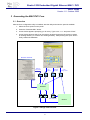
1
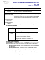
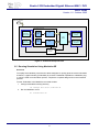
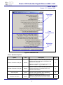
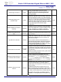
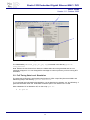
Stratix II GX Embedded Gigabit Ethernet MAC / PHY
User's Guide
Version 1.0 - October 2005
Stratix II GX Embedded Gigabit
Ethernet MAC / PHY
User's Guide
1
Stratix II GX Embedded Gigabit Ethernet MAC / PHY
User's Guide
Version 1.0 - October 2005
Contents
1
DESIGN KIT INSTALLATION......................................................................................................... 3
1.1
1.2
PLATFORM SPECIFIC JAVA RUNTIME INSTALLATION ...................................................................... 3
DESIGN KIT INSTALLATION ............................................................................................................ 3
2
DESIGN FLOW................................................................................................................................ 4
3
GENERATING THE MAC/PHY CORE............................................................................................ 5
3.1 OVERVIEW ................................................................................................................................... 5
3.2 CORE CONFIGURATION OPTIONS .................................................................................................. 6
3.3 DESIGN KIT DATABASE ................................................................................................................. 7
3.4 SIMULATION ENVIRONMENT .......................................................................................................... 7
3.5 RUNNING SIMULATION USING MODELSIM SE ................................................................................. 8
Overview .......................................................................................................................................... 8
Testbuilder Options.......................................................................................................................... 9
3.6 RUNNING SIMULATION USING MODELSIM PE OR MODELSIM AE.................................................... 13
Overview ........................................................................................................................................ 13
Simulation Options......................................................................................................................... 13
3.7 DESIGN IMPLEMENTATION WITH QUARTUS II ................................................................................ 16
3.8 VQM NETLIST GENERATION ....................................................................................................... 16
3.9 FULL TIMING GATE LEVEL SIMULATION ........................................................................................ 17
4
CONTACT ..................................................................................................................................... 18
List of Figures
Figure 1: Design Flow Overview ............................................................................................................. 5
Figure 2: MAC Core Configuration Panel ............................................................................................... 6
Figure 3: Testbench Setup Overview...................................................................................................... 8
Figure 4: Running Testbuilder Overview................................................................................................. 9
Figure 5: Testbuilder Panel ................................................................................................................... 10
Figure 6: VQM Netlist Generation......................................................................................................... 17
List of Tables
Table 1: Core Configuration Options ...................................................................................................... 7
Table 2: Design Kit Directory Structure................................................................................................... 7
Table 3: Simulation Options .................................................................................................................. 10
Table 4: MAC Configuration Options .................................................................................................... 12
Table 5: Testbuilder Simulation Control................................................................................................ 13
Table 6: Simulation Options .................................................................................................................. 13
Table 7: MAC Configuration Options .................................................................................................... 15
2
Stratix II GX Embedded Gigabit Ethernet MAC / PHY
User's Guide
Version 1.0 - October 2005
1 Design Kit Installation
1.1 Platform Specific JAVA Runtime Installation
To be able to run the MAC Design Kit delivery and configuration tool, a Java runtime must be
present on the system. The design kit needs the Java Runtime Environment Version 1.2.x
(JRE1.2) or later.
To determine if and which Java version is installed on your system, open a Shell and type "java
-version". If you get errors then the runtime is not installed. If the version is lower than 1.3.x a
newer package must be installed.
A platform specific package (The runtime standard edition 1.3, JRE 1.3, is sufficient) can be
downloaded from the Sum Microsystems WEB site:
http://java.sun.com/j2se.
To install the runtime environment, follow the instructions included in the download package:
• Windows platform: Execute the self-extracting archive.
• Solaris/Linux: Extract the package in a directory and add the bin directory to the PATH
environment variable.
1.2 Design Kit Installation
A single executable Java delivery and configuration utility, common to all platforms, is provided,
ethpack.jar. The utility generates all the required design files as well as the required scripts for
simulation and implementation.
After unzipping the distribution in any directory 1 , the Java application can be started immediately:
• Windows users:
1. Double-click on the ethpack.jar file found in the distribution top directory
• UNIX (Solaris/Linux) users:
1
1. Goto the installation directory:
$> cd <installation directory>
2. Execute the Java application:
$> java -jar ethpack.jar
Use the extract feature of your unzip tool. Avoid using drag&drop as it does not preserve the directory structure.
3
Stratix II GX Embedded Gigabit Ethernet MAC / PHY
User's Guide
Version 1.0 - October 2005
2 Design Flow
The different steps of the Embedded Gigabit Ethernet MAC-PHY Design are:
•
Core generation
•
RTL Simulation
•
Synthesis
•
Implementation using Quartus II
•
Gate-Level Simulation – Not available with Evaluation License
The design kit provides scripts for ease of use, fast design and verification / implementation turnaround.
The tools primarily supported are:
•
Simulation: Modelsim Version 5.7a or higher
•
Synthesis: Altera Quartus II V5.1 or higher
•
Implementation: Altera Quartus II V5.1 or higher
4
Stratix II GX Embedded Gigabit Ethernet MAC / PHY
User's Guide
Version 1.0 - October 2005
3 Generating the MAC/PHY Core
3.1 Overview
After the Core configuration utility is installed, start the utility and when the panel is available:
1. Select the Core options on the panel
2. Press the "Generate HDL" button.
3. A new window appears prompting you for a key. Type LbNH-sC79 and press “Enter”.
4. A new window appears which can be used to navigate through the file system to select
an existing directory or create a new working directory. After pressing the "open" button
finally creates the database.
MorethanIP TestBuilder
Testbench
Configuration
VHDL
Testbench
Constraint
Template
VHDL
Design FILES
Simulation
Control
ModelSim
ModelSim
VHO
SDF
User Constraints
Figure 1: Design Flow Overview
5
Quartus
Quartus
Stratix II GX Embedded Gigabit Ethernet MAC / PHY
User's Guide
Version 1.0 - October 2005
3.2 Core Configuration Options
The Core is fully configurable and a user friendly GUI is provided to simplify configuration. To
optimize the core for the intended application environment, several options are available which can
be modified before the actual database is generated as described before.
Figure 2: MAC Core Configuration Panel
6
Stratix II GX Embedded Gigabit Ethernet MAC / PHY
User's Guide
Version 1.0 - October 2005
Table 1: Core Configuration Options
Option
Description
Technology
The Core is optimized for Altera Stratix II GX devices.
Maximum Frame Length
Maximum Frame Length. Defines a 14-Bit maximum frame length used by
the MAC receive logic to check frames.
Pause Frame Quanta
Receive Pause Quanta. 16-Bit value sets, in increment of 512 Ethernet bit
times, the pause quanta used in each Pause Frame sent to the remote
Ethernet device.
Enable Promiscuous
Receive Mode
When selected, all frames are received without Unicast address filtering.
Insert MAC Address on
Transmit
If select the MAC overwrites the source MAC address with the MAC set on
the Core signal mac_addr. If disabled, the source MAC address received
from the transmit application transmitted is not modified by the MAC.
3.3 Design Kit Database
Table 2: Design Kit Directory Structure
Directory
Description
models
Ethernet Frame generator and monitor models.
quartus
Contains the netist for Altera Stratix implementation and a script
to control the Altera Quartus design software.
simulation
Scripts to configure and execute RTL and Gate-Level Simulation
as well the Modelsim integrated TestBuilder.
source
Encrypted VHDL design source files, testbench and
configuration files.
3.4 Simulation Environment
A complete testbench is provided (File testbench.vhd in directory source/testbench/vhdl)
which implements the Core together with a simulation control state machine and the following
drivers and monitors.
•
GMII Ethernet Frame Generator: Configurable Ethernet Gigabit Ethernet frame generator
with GMII interface.
•
GMII Ethernet Frame Monitor: Gigabit Ethernet frame monitor with GMII interface.
•
Ethernet Frame Generator (FIFO mode): Configurable Ethernet frame generator
simulating a user application connected to the MAC transmit FIFO interface.
•
Ethernet Monitor (FIFO mode): Ethernet frame checker simulating a user application
connected to the MAC receive FIFO interface.
•
PCS: 1000Base-X PCS function that decodes / encodes data from / to the MAC / PHY
Core and controls the Auto-Negotiation process within the testbench.
7
Stratix II GX Embedded Gigabit Ethernet MAC / PHY
User's Guide
Version 1.0 - October 2005
mtip_sim_pack.vhd
Testbench
Unit Under Test (uut)
Ethernet
Ethernet Frame
Frame
Generator
Generator
(FIFO
(FIFO mode)
mode)
Transmit
FIFO
GMII
GMII
Ethernet
Ethernet Frame
Frame
Monitor
Monitor
TX
PCS
Model
Ethernet
Ethernet
Monitor
Monitor
(FIFO
(FIFO mode)
mode)
Receive
FIFO
RX
GMII
GMII
Ethernet
Ethernet Frame
Frame
Generator
Generator
Testbench
Testbench
Control
Pause
Control
Figure 3: Testbench Setup Overview
3.5 Running Simulation Using Modelsim SE
Overview
To simplify the evaluation process and to allow designers to quickly generate custom simulation
scenarios, a graphical utility (Testbuilder) is provided. Testbuilder operates as a Modelsim plugin, which is used to set simulation options, compile the complete design and run the simulation
process.
To start Testbuilder in the Modelsim command window:
1. Change to Modelsim working directory
cd <Design Kit Root>/simulation
2. Run the Modelsim macro
do testbuilder.do
8
Stratix II GX Embedded Gigabit Ethernet MAC / PHY
User's Guide
Version 1.0 - October 2005
2
1
Figure 4: Running Testbuilder Overview
Important note:
The system variable QUARTUS_ROOTDIR should be set to the Quartus software
installation directory so that the Altera libraries can be linked during RTL or Gate level
simulations.
Testbuilder Options
A single VHDL configuration file configures the Testbench:
•
source/package/vhdl/mtip_sim_pack.vhd
The file can be modified to implement different simulation scenarios. To ease the configuration,
a graphical tool, TestBuilder is provided that modifies the configuration file. TestBuilder is a
TCL/TK extension written for the ModelSim Simulator, which is fully integrated in the ModelSim
framework.
9
Stratix II GX Embedded Gigabit Ethernet MAC / PHY
User's Guide
Version 1.0 - October 2005
Simulation
Control
Core
Configuration
Modelsim
Control
Figure 5: Testbuilder Panel
Table 3: Simulation Options
Option
Number of Frames in RX path
Unit
Frames
Description
Sets the number of frames that are generated by
the Ethernet frame Generator connected to the
Receive PHY interface.
Default
5
If set to 0, a Serdes loopback test is performed
with the Core pin loop_ena set to '1'.
Sets the number of frames that are generated by
the frame Generator connected to the Core
transmit FIFO interface.
5
Bytes
Sets the inter-packet gap (IGP) used by the
Ethernet Frame generator when generating
frames to the RX PHY interface.
12
Bytes
Defines the payload length of the first frame
generated by the Ethernet and FIFO models.
100
Number of Frames in TX path
Frames
IPG in RX path
Length of first frame
10
Stratix II GX Embedded Gigabit Ethernet MAC / PHY
User's Guide
Version 1.0 - October 2005
Frame length increment
Generated Frames max.
payload length
Bytes
Frame payload length increment. During
simulation frames are generated starting from
"length of first frame" incrementing with each
frame generated.
Bytes
Defines the payload maximum length used by the
Ethernet Generator models. This value specifies
the wrap around for the frame length of generated
frames. I.e. if the frame length increment would
exceed this value it wraps around to zero. Can be
used to test frame length error detection, when set
to any value larger than the MAC length
configuration.
1500
True
False
Enable Padding of Frames in
RX Path
Boolean
If enabled, RX PHY Generator model generated
frames are padded to 64 octets in length (normal
mode). If disabled, no padding occurs and
erroneous frames will be sent to the MAC RX.
Enable VLAN frames for all
tests
Boolean
If enabled, all frames sent/received will be VLAN
type of frames
1
Inhibits the Testbench RX FIFO monitor reading
the RX FIFO, after this amount of frames has
been sent to the RX.
Stop RX FIFO read after
Restart RX FIFO read after
Frames
RX FIFO
clocks
Can be used to test Flow-Control behaviour. If
more frames are received, the FIFO will get filled.
When the threshold level is reached, a PauseFrame will be generated by the MAC TX. If set to
0, the RX FIFO read is never paused.
Number of clock cycles, the RX FIFO should not
be read after it has been stopped. Only relevant if
the previous configuration (read stop) was set to a
non-null value.
0
10
After this number of RX FIFO clock cycles, the RX
FIFO will be emptied again.
Generate Frames with Errors
on Transmit FIFO Interface
Boolean
Enable Transmit Error Generation the Core
Transmit Interface. When selected, the transmit
FIFO signal ff_tx_err is asserted with
ff_tx_eop to signal an Error. When disabled,
the FIFO error is signalled, ff_tx_err is never
set to '1'.
False
If enabled (true) the Testbench will stop the RX
(PHY) Frame generator, if the MAC sends a
Pause Frame. This simulates a usual flow-control
chain correctly.
Testbench reacts on Pause
Frames
Boolean
If disabled (False) Pause Frames sent by the
MAC are ignored by the Testbench and the RX
(PHY) Frame generator will never pause. This can
be used to test the MACs FIFO overflow behavior.
This option has no effect, if loopback mode is
enabled (i.e. Frame generation in RX path is set
0).
11
True
Stratix II GX Embedded Gigabit Ethernet MAC / PHY
User's Guide
Version 1.0 - October 2005
Force Xoff Frame Generation
at (clocks)
Force Xon Frame Generation
at (clocks)
Integer
XOFF Pause Frame Generation. Set the time for
to generate a XOFF Frame with the Core
command pin xoff_gen. When set to 0, XOFF
Frame generation is disabled.
0
Integer
XON Pause Frame Generation. Set the time for to
generate a XON Frame with the Core command
pin xon_gen. When set to 0, XON Frame
generation is disabled.
0
Table 4: MAC Configuration Options
Option
Unit
Description
Default
MAC CONFIG: Transmit FIFO
Section Empty Threshold
Integer
Set the Transmit FIFO Section empty threshold
to any value between 0 and 63 (Maximum
memory depth).
16
MAC CONFIG: Transmit FIFO
Section Full Threshold
Integer
Set the Transmit FIFO Section full threshold to
any value between 0 and 63 (Maximum memory
depth).
16
MAC CONFIG: Receive FIFO
Section Empty Threshold
Integer
Set the Receive FIFO Section empty threshold
to any value between 0 and 63 (Maximum
memory depth).
0
MAC CONFIG: Receive FIFO
Section Full Threshold
Integer
Set the Receive FIFO Section full threshold to
any value between 0 and 63 (Maximum memory
depth).
16
MAC CONFIG: Enable AutoNegotiation
Boolean
Enable Auto-Negotiation. When selected, the
Core performs auto-negotiation to check the link
with the Link Partner before simulation starts.
After simulation, the Auto-Negotiation is
restarted with the Core signal an_enable set to
'0'. When disabled, non Auto-Negotiation is
performed.
True
MAC CONFIG: Ignore Pause
Frames
Boolean
Ignore Pause Frames. When enabled, received
Pause Frames are ignored, when disable,
Pause Frames are decoded.
False
Boolean
Enable Receive Padding Remove. When
enabled, Frames are provided on the Client
Interface without padding, when disabled,
Frames are provided on the Client Interface with
padding.
True
MAC CONFIG: Forward CRC
Boolean
Enable CRC Forwarding. When selected, CRC
is passed transparently from the Transmit Client
Interface to line and, is preserved on the
Received Client Interface.
False
MAC CONFIG: Transmit IPG
Length
Integer
Transmit Inter-Packet Gap. Defined, in Bytes,
the IPG between transmitted Frames.
MAC CONFIG: Remove
Frame Padding
12
12
Stratix II GX Embedded Gigabit Ethernet MAC / PHY
User's Guide
Version 1.0 - October 2005
Table 5: Testbuilder Simulation Control
Testbuilder Panel Option
Description
Compile Database before
Simulation (VHDL)
When enabled, the Core simulation database is refreshed with the Core
configuration options. The option must be enabled at least once after a
new Core database was generated.
Run Simulation Only
When selected, starts the RTL simulation with all the options defined in
the Testbuilder panel ignored (Previous configuration used).
Configure and Start Simulation
When selected, the options defined on the Testbuilder panel are saved
before the RTL simulation is performed.
Run Gate-Level
When selected, the options defined on the Testbuilder panel are saved
before the Gate level simulation is performed.
When running a simulation, a set of waveforms is displayed; error and information messages are
issued in the Modelsim standard output.
3.6 Running Simulation Using Modelsim PE or Modelsim AE
Overview
Modifying the file mtip_sim_pack.vhd located in the directory source/package/vhdl
creates a custom simulation scenario. The Core files and dependencies are available in the file
comp.do (In Directory simulation), the testbench file and simulation models files are listed
in the file sim.do. The files comp.do and sim.do should be modified and adapted with the
simulator command.
Once a scenario has been created, the following steps should be followed:
1. Change to the simulation directory.
2. Compile the Core database:
•
do comp.do
3. Compile the Simulation database and run simulation:
•
do sim.do
Simulation Options
The simulation is controlled and is configured with a set of parameters set in the file
mtip_sim_pack.vhd.
Table 6: Simulation Options
Option
TB_RXFRAMES
Unit
Frames
Description
Sets the number of frames that are generated by
the Ethernet frame Generator connected to the
Receive PHY interface.
If set to 0, a Serdes loopback test is performed
with the Core pin loop_ena set to '1'.
13
Default
5
Stratix II GX Embedded Gigabit Ethernet MAC / PHY
User's Guide
Version 1.0 - October 2005
Sets the number of frames that are generated by
the frame Generator connected to the Core
transmit FIFO interface.
5
Bytes
Sets the inter-packet gap (IGP) used by the
Ethernet Frame generator when generating
frames to the RX PHY interface.
12
Bytes
Defines the payload length of the first frame
generated by the Ethernet and FIFO models.
100
Bytes
Frame payload length increment. During
simulation frames are generated starting from
"length of first frame" incrementing with each
frame generated.
1
Bytes
Defines the payload maximum length used by the
Ethernet Generator models. This value specifies
the wrap around for the frame length of generated
frames. I.e. if the frame length increment would
exceed this value it wraps around to zero. Can be
used to test frame length error detection, when set
to any value larger than the MAC length
configuration.
1500
True
False
TB_TXFRAMES
Frames
TB_RXIPG
TB_LENSTART
TB_LENSTEP
TB_LENMAX
TB_ENA_PADDING
Boolean
If enabled, RX PHY Generator model generated
frames are padded to 64 octets in length (normal
mode). If disabled, no padding occurs and
erroneous frames will be sent to the MAC RX.
TB_ENA_VLAN
Boolean
If enabled, all frames sent/received will be VLAN
type of frames
Inhibits the Testbench RX FIFO monitor reading
the RX FIFO, after this amount of frames has
been sent to the RX.
TB_STOPREAD
TB_HOLDREAD
Frames
RX FIFO
clocks
Can be used to test Flow-Control behaviour. If
more frames are received, the FIFO will get filled.
When the threshold level is reached, a PauseFrame will be generated by the MAC TX. If set to
0, the RX FIFO read is never paused.
Number of clock cycles, the RX FIFO should not
be read after it has been stopped. Only relevant if
the previous configuration (read stop) was set to a
non-null value.
0
10
After this number of RX FIFO clock cycles, the RX
FIFO will be emptied again.
TB_TX_FF_ERR
Boolean
Enable Transmit Error Generation the Core
Transmit Interface. When selected, the transmit
FIFO signal ff_tx_err is asserted with
ff_tx_eop to signal an Error. When disabled,
the FIFO error is signalled, ff_tx_err is never
set to '1'.
TB_PAUSECONTROL
Boolean
If enabled (true) the Testbench will stop the RX
(PHY) Frame generator, if the MAC sends a
14
False
True
Stratix II GX Embedded Gigabit Ethernet MAC / PHY
User's Guide
Version 1.0 - October 2005
Pause Frame. This simulates a usual flow-control
chain correctly.
If disabled (False) Pause Frames sent by the
MAC are ignored by the Testbench and the RX
(PHY) Frame generator will never pause. This can
be used to test the MACs FIFO overflow behavior.
This option has no effect, if loopback mode is
enabled (i.e. Frame generation in RX path is set
0).
TB_TRIGGERXOFF
TB_TRIGGERXON
Integer
XOFF Pause Frame Generation. Set the time for
to generate a XOFF Frame with the Core
command pin xoff_gen. When set to 0, XOFF
Frame generation is disabled.
0
Integer
XON Pause Frame Generation. Set the time for to
generate a XON Frame with the Core command
pin xon_gen. When set to 0, XON Frame
generation is disabled.
0
Table 7: MAC Configuration Options
Option
Unit
Description
Default
TX_FIFO_SE
Integer
Set the Transmit FIFO Section empty threshold
to any value between 0 and 63 (Maximum
memory depth).
16
TX_FIFO_SF
Integer
Set the Transmit FIFO Section full threshold to
any value between 0 and 63 (Maximum memory
depth).
16
RX_FIFO_SE
Integer
Set the Receive FIFO Section empty threshold
to any value between 0 and 63 (Maximum
memory depth).
0
RX_FIFO_SF
Integer
Set the Receive FIFO Section full threshold to
any value between 0 and 63 (Maximum memory
depth).
16
TB_ENA_AUTONEG
Boolean
Enable Auto-Negotiation. When selected, the
Core performs auto-negotiation to check the link
with the Link Partner before simulation starts.
After simulation, the Auto-Negotiation is
restarted with the Core signal an_enable set to
'0'. When disabled, non Auto-Negotiation is
performed.
True
TB_IGNORE_PAUSE
Boolean
Ignore Pause Frames. When enabled, received
Pause Frames are ignored, when disable,
Pause Frames are decoded.
False
Boolean
Enable Receive Padding Remove. When
enabled, Frames are provided on the Client
Interface without padding, when disabled,
Frames are provided on the Client Interface with
padding.
True
TB_PAD_ENA
15
Stratix II GX Embedded Gigabit Ethernet MAC / PHY
User's Guide
Version 1.0 - October 2005
TB_CRC_FWD
Boolean
Enable CRC Forwarding. When selected, CRC
is passed transparently from the Transmit Client
Interface to line and, is preserved on the
Received Client Interface.
TB_IPG_LEN
Integer
Transmit Inter-Packet Gap. Defined, in Bytes,
the IPG between transmitted Frames.
False
3.7 Design Implementation with Quartus II
Two TCL script (quartus.tcl) is provided in the design kit directory quartus, which performs
the following actions:
1. Create project
2. Build database
3. Set timing constraints
4. Set I/O Fast Register constraint on fast I/O signals
5. Run Quartus fitter
6. Reports design timing and timing violations
7. Generates VHO VHDL gate level netlist and SDO timing file used during Gate level
simulation
The TCL script can run from the Quartus II graphical interface or in batch mode.
•
Graphical Mode:
1.
In Quartus II TCL console Change to Quartus working directory
cd <Design Kit Root>/quartus
2.
Run the design TCL script
source quartus.tcl
3.8 VQM Netlist Generation
After you obtain a core license from Altera, a VQM netlist of the Core can be generated with the
Quartus II software. The VQM netlist can be used to integrate the Core in a customer design.
To create the VQM netlist:
1. Analyze and Synthesize the Core
2. Generate the VQM Netlist
16
12
Stratix II GX Embedded Gigabit Ethernet MAC / PHY
User's Guide
Version 1.0 - October 2005
1
2
Figure 6: VQM Netlist Generation
The VQM Netlist (embedded_gige_mac_phy.vqm) is created in the directory quartus/
atom_netlists.
Note: Without the free license from Altera, the VQM netlist cannot be generated and an error
message will appear. You can disregard this message as it will not prevent you from running RTL
simulation.
3.9 Full Timing Gate Level Simulation
The gate level verification is performed using Quartus II VHDL output files (Structural VHDL and
SDF timing files) in the directory quartus/simulation.
To run the gate level simulation with Modelsim, use as described in chapters “3.5” and following. A
gate level simulation when the Testbuilder simulation option “Run Gate-Level” is used.
With a Modelsim PE or Modelsim AE, run the script gate.do:
•
do gate.do
17
Stratix II GX Embedded Gigabit Ethernet MAC / PHY
User's Guide
Version 1.0 - October 2005
4 Contact
Altera
For the most up-to-date information about Altera products, go to the Altera world-wide
web site at www.altera.com. For technical support on this product, go to
www.altera.com/mysupport. For additional information about Altera products, consult
the sources shown below.
Information Type
Technical support
USA & Canada
All Other Locations
www.altera.com/mysupport
www.altera.com/mysupport
(800) 800-EPLD (3753)
+1 408-544-8767
(7:00 a.m. to 5:00 p.m. Pacific Time)
7:00 a.m. to 5:00 p.m. (GMT –8:00)
Pacific Time
Product literature
www.altera.com
www.altera.com
Altera literature services
[email protected]
[email protected]
Non-technical customer
service
(800) 767-3753
+1 408-544-7000
FTP site
ftp.altera.com
7:00 a.m. to 5:00 p.m. (GMT –8:00)
Pacific Time
ftp.altera.com
MorethanIP
E-Mail
: [email protected]
Internet : www.morethanip.com
Europe
Muenchner Strasse 199
D-85757 Karlsfeld
Germany
Tel
: +49 (0) 8131 333939 0
FAX
: +49 (0) 8131 333939 1
18