1
10-Gbps Ethernet MAC MegaCore Function User Guide
10-Gbps Ethernet MAC MegaCore Function
User Guide
101 Innovation Drive
San Jose, CA 95134
www.altera.com
UG-01083-3.4
Document last updated for Altera Complete Design Suite version:
Document publication date:
14.0
August 2014
Feedback Subscribe
Copyright © 2014 Altera Corporation. All rights reserved. Altera, The Programmable Solutions Company, the stylized Altera logo, and specific device designations
are trademarks and/or service marks of Altera Corporation in the U.S. and other countries. All other words and logos identified as trademarks and/or service marks
are the property of Altera Corporation or their respective owners. Altera products are protected under numerous U.S. and foreign patents and pending applications,
maskwork rights, and copyrights. Altera warrants performance of its semiconductor products to current specifications in accordance with Altera's standard
warranty, but reserves the right to make changes to any products and services at any time without notice. Altera assumes no responsibility or liability arising out of
the application or use of any information, product, or service described herein except as expressly agreed to in writing by Altera. Altera customers are advised to
obtain the latest version of device specifications before relying on any published information and before placing orders for products or services.
10-Gbps Ethernet MAC MegaCore Function User Guide
August 2014 Altera Corporation
Contents
Chapter 1. About This IP Core
1.1. Features . . . . . . . . . . . . . . . . . . . . . . . . . . . . . . . . . . . . . . . . . . . . . . . . . . . . . . . . . . . . . . . . . . . . . . . . . . . . 1–1
1.2. Release Information . . . . . . . . . . . . . . . . . . . . . . . . . . . . . . . . . . . . . . . . . . . . . . . . . . . . . . . . . . . . . . . . . . 1–2
1.3. Device Family Support . . . . . . . . . . . . . . . . . . . . . . . . . . . . . . . . . . . . . . . . . . . . . . . . . . . . . . . . . . . . . . . 1–3
1.4. IP Core Verification . . . . . . . . . . . . . . . . . . . . . . . . . . . . . . . . . . . . . . . . . . . . . . . . . . . . . . . . . . . . . . . . . . 1–3
1.4.1. Simulation Environment . . . . . . . . . . . . . . . . . . . . . . . . . . . . . . . . . . . . . . . . . . . . . . . . . . . . . . . . . . 1–3
1.4.2. Compatibility Testing Environment . . . . . . . . . . . . . . . . . . . . . . . . . . . . . . . . . . . . . . . . . . . . . . . . 1–4
1.5. Performance and Resource Utilization . . . . . . . . . . . . . . . . . . . . . . . . . . . . . . . . . . . . . . . . . . . . . . . . . . 1–4
Chapter 2. Getting Started with Altera IP Cores
2.1. Introduction to Altera IP Cores . . . . . . . . . . . . . . . . . . . . . . . . . . . . . . . . . . . . . . . . . . . . . . . . . . . . . . . . 2–1
2.2. Installing and Licensing IP Cores . . . . . . . . . . . . . . . . . . . . . . . . . . . . . . . . . . . . . . . . . . . . . . . . . . . . . . 2–1
2.2.1. OpenCore Plus IP Evaluation . . . . . . . . . . . . . . . . . . . . . . . . . . . . . . . . . . . . . . . . . . . . . . . . . . . . . . 2–2
2.3. IP Catalog and Parameter Editor . . . . . . . . . . . . . . . . . . . . . . . . . . . . . . . . . . . . . . . . . . . . . . . . . . . . . . . 2–2
2.4. Using the Parameter Editor . . . . . . . . . . . . . . . . . . . . . . . . . . . . . . . . . . . . . . . . . . . . . . . . . . . . . . . . . . . 2–3
2.5. Customizing and Generating IP Cores . . . . . . . . . . . . . . . . . . . . . . . . . . . . . . . . . . . . . . . . . . . . . . . . . . 2–4
2.6. Specifying the Parameters . . . . . . . . . . . . . . . . . . . . . . . . . . . . . . . . . . . . . . . . . . . . . . . . . . . . . . . . . . . . . 2–5
2.7. Upgrading Outdated IP Cores . . . . . . . . . . . . . . . . . . . . . . . . . . . . . . . . . . . . . . . . . . . . . . . . . . . . . . . . . 2–5
2.8. Simulating IP Cores . . . . . . . . . . . . . . . . . . . . . . . . . . . . . . . . . . . . . . . . . . . . . . . . . . . . . . . . . . . . . . . . . . 2–6
2.9. 10GbE MAC Parameter Settings . . . . . . . . . . . . . . . . . . . . . . . . . . . . . . . . . . . . . . . . . . . . . . . . . . . . . . . 2–8
Chapter 3. 10GbE MAC Design Examples
3.1. Software and Hardware Requirements . . . . . . . . . . . . . . . . . . . . . . . . . . . . . . . . . . . . . . . . . . . . . . . . . 3–1
3.2. 10GbE Design Example Components . . . . . . . . . . . . . . . . . . . . . . . . . . . . . . . . . . . . . . . . . . . . . . . . . . . 3–2
3.2.0.1. Ethernet Loopback Module . . . . . . . . . . . . . . . . . . . . . . . . . . . . . . . . . . . . . . . . . . . . . . . . . . . . 3–3
3.2.0.2. Base Addresses . . . . . . . . . . . . . . . . . . . . . . . . . . . . . . . . . . . . . . . . . . . . . . . . . . . . . . . . . . . . . . 3–4
3.3. 10GbE Design Example Files . . . . . . . . . . . . . . . . . . . . . . . . . . . . . . . . . . . . . . . . . . . . . . . . . . . . . . . . . . 3–5
3.4. Creating a New 10GbE Design . . . . . . . . . . . . . . . . . . . . . . . . . . . . . . . . . . . . . . . . . . . . . . . . . . . . . . . . . 3–6
3.5. 10GbE Design Example Parameter Settings . . . . . . . . . . . . . . . . . . . . . . . . . . . . . . . . . . . . . . . . . . . . . . 3–8
3.6. 10GbE Testbenches . . . . . . . . . . . . . . . . . . . . . . . . . . . . . . . . . . . . . . . . . . . . . . . . . . . . . . . . . . . . . . . . . . . 3–8
3.6.1. 10GbE Testbench . . . . . . . . . . . . . . . . . . . . . . . . . . . . . . . . . . . . . . . . . . . . . . . . . . . . . . . . . . . . . . . . 3–8
3.6.2. 10GbE Testbench Component . . . . . . . . . . . . . . . . . . . . . . . . . . . . . . . . . . . . . . . . . . . . . . . . . . . . . 3–9
3.6.3. 10GbE Testbench Files . . . . . . . . . . . . . . . . . . . . . . . . . . . . . . . . . . . . . . . . . . . . . . . . . . . . . . . . . . . . 3–9
3.6.4. 10GbE Testbench Simulation Flow . . . . . . . . . . . . . . . . . . . . . . . . . . . . . . . . . . . . . . . . . . . . . . . . 3–11
3.6.5. Simulating the 10GbE Testbench with the ModelSim Simulator . . . . . . . . . . . . . . . . . . . . . . . 3–11
3.6.6. Enabling Local Loopback . . . . . . . . . . . . . . . . . . . . . . . . . . . . . . . . . . . . . . . . . . . . . . . . . . . . . . . . 3–12
3.6.7. 10GbE Simulation Timing Diagrams . . . . . . . . . . . . . . . . . . . . . . . . . . . . . . . . . . . . . . . . . . . . . . . 3–13
3.7. 10GbE Design Example Compilation and Verification in Hardware . . . . . . . . . . . . . . . . . . . . . . . . 3–15
3.7.1. Compiling the 10GbE Design . . . . . . . . . . . . . . . . . . . . . . . . . . . . . . . . . . . . . . . . . . . . . . . . . . . . . 3–15
3.7.2. Verifying the 10GbE Design in Hardware . . . . . . . . . . . . . . . . . . . . . . . . . . . . . . . . . . . . . . . . . . 3–17
3.7.3. Debugging . . . . . . . . . . . . . . . . . . . . . . . . . . . . . . . . . . . . . . . . . . . . . . . . . . . . . . . . . . . . . . . . . . . . . 3–17
3.7.4. 10GbE Design Transmit and Receive Latencies . . . . . . . . . . . . . . . . . . . . . . . . . . . . . . . . . . . . . . 3–18
3.7.5. 10GbE Design Performance and Resource Utilization . . . . . . . . . . . . . . . . . . . . . . . . . . . . . . . . 3–19
Chapter 4. 10GbE MAC with IEEE1588v2 Design Example
4.1. Software Requirements . . . . . . . . . . . . . . . . . . . . . . . . . . . . . . . . . . . . . . . . . . . . . . . . . . . . . . . . . . . . . . . 4–1
4.2. 10GbE with IEEE 1588v2 Design Example Components . . . . . . . . . . . . . . . . . . . . . . . . . . . . . . . . . . . 4–2
4.2.1. Base Addresses . . . . . . . . . . . . . . . . . . . . . . . . . . . . . . . . . . . . . . . . . . . . . . . . . . . . . . . . . . . . . . . . . . 4–3
August 2014
Altera Corporation
10-Gbps Ethernet MAC MegaCore Function User Guide
Contents
iv
4.3. 10GbE with IEEE 1588v2 Design Example Files . . . . . . . . . . . . . . . . . . . . . . . . . . . . . . . . . . . . . . . . . . 4–4
4.4. Creating a New 10GbE with IEEE 1588v2 Design . . . . . . . . . . . . . . . . . . . . . . . . . . . . . . . . . . . . . . . . . 4–4
4.5. 10GbE with IEEE 1588v2 Testbench . . . . . . . . . . . . . . . . . . . . . . . . . . . . . . . . . . . . . . . . . . . . . . . . . . . . 4–5
4.5.1. 10GbE with IEEE 1588v2 Testbench . . . . . . . . . . . . . . . . . . . . . . . . . . . . . . . . . . . . . . . . . . . . . . . . 4–5
4.5.2. 10GbE with IEEE 1588v2 Testbench Components . . . . . . . . . . . . . . . . . . . . . . . . . . . . . . . . . . . . . 4–5
4.5.3. 10GbE with IEEE 1588v2 Testbench Files . . . . . . . . . . . . . . . . . . . . . . . . . . . . . . . . . . . . . . . . . . . . 4–6
4.5.4. 10GbE with IEEE 1588v2 Testbench Simulation Flow . . . . . . . . . . . . . . . . . . . . . . . . . . . . . . . . . 4–6
4.5.5. Simulating 10GbE with IEEE 1588v2 Testbench with ModelSim Simulator . . . . . . . . . . . . . . . 4–7
Chapter 5. 1G/10GbE MAC Design Example
5.1. Software and Hardware Requirements . . . . . . . . . . . . . . . . . . . . . . . . . . . . . . . . . . . . . . . . . . . . . . . . . 5–1
5.2. 1G/10GbE Design Example Components . . . . . . . . . . . . . . . . . . . . . . . . . . . . . . . . . . . . . . . . . . . . . . . 5–2
5.2.1. Reconfiguration Bundle Parameters . . . . . . . . . . . . . . . . . . . . . . . . . . . . . . . . . . . . . . . . . . . . . . . . 5–4
5.2.2. Base Addresses . . . . . . . . . . . . . . . . . . . . . . . . . . . . . . . . . . . . . . . . . . . . . . . . . . . . . . . . . . . . . . . . . . 5–4
5.3. 1G/10GbE Design Example Files . . . . . . . . . . . . . . . . . . . . . . . . . . . . . . . . . . . . . . . . . . . . . . . . . . . . . . . 5–5
5.4. Creating a New 1G/10GbE Design . . . . . . . . . . . . . . . . . . . . . . . . . . . . . . . . . . . . . . . . . . . . . . . . . . . . . 5–6
5.5. 1G/10GbE Testbench . . . . . . . . . . . . . . . . . . . . . . . . . . . . . . . . . . . . . . . . . . . . . . . . . . . . . . . . . . . . . . . . . 5–6
5.5.1. 1G/10GbE Testbench . . . . . . . . . . . . . . . . . . . . . . . . . . . . . . . . . . . . . . . . . . . . . . . . . . . . . . . . . . . . . 5–6
5.5.2. 1G/10GbE Testbench Components . . . . . . . . . . . . . . . . . . . . . . . . . . . . . . . . . . . . . . . . . . . . . . . . . 5–7
5.5.3. 1G/10GbE Testbench Files . . . . . . . . . . . . . . . . . . . . . . . . . . . . . . . . . . . . . . . . . . . . . . . . . . . . . . . . 5–7
5.5.4. 1G/10GbE Testbench Simulation Flow . . . . . . . . . . . . . . . . . . . . . . . . . . . . . . . . . . . . . . . . . . . . . . 5–9
5.5.4.1. 1G/10Gb Ethernet Mode . . . . . . . . . . . . . . . . . . . . . . . . . . . . . . . . . . . . . . . . . . . . . . . . . . . . . . 5–9
5.5.4.2. Backplane-KR Mode . . . . . . . . . . . . . . . . . . . . . . . . . . . . . . . . . . . . . . . . . . . . . . . . . . . . . . . . . 5–10
5.5.5. Simulating the 1G/10GbE Testbench with the ModelSim Simulator . . . . . . . . . . . . . . . . . . . . 5–10
5.5.6. 1G/10GbE Simulation Timing Diagrams . . . . . . . . . . . . . . . . . . . . . . . . . . . . . . . . . . . . . . . . . . . 5–12
5.6. 1G/10GbE Design Example Compilation . . . . . . . . . . . . . . . . . . . . . . . . . . . . . . . . . . . . . . . . . . . . . . 5–13
5.6.1. Compiling the 1G/10GbE Design . . . . . . . . . . . . . . . . . . . . . . . . . . . . . . . . . . . . . . . . . . . . . . . . . 5–13
5.6.2. 1G/10GbE Design Performance and Resource Utilization . . . . . . . . . . . . . . . . . . . . . . . . . . . . 5–14
Chapter 6. 10M-10GbE MAC with IEEE 1588v2 Design Example
6.1. Software and Hardware Requirements . . . . . . . . . . . . . . . . . . . . . . . . . . . . . . . . . . . . . . . . . . . . . . . . . 6–1
6.2. 10M-10GbE MAC with IEEE 1588v2 Design Example Components . . . . . . . . . . . . . . . . . . . . . . . . . 6–1
6.2.1. Base Addresses . . . . . . . . . . . . . . . . . . . . . . . . . . . . . . . . . . . . . . . . . . . . . . . . . . . . . . . . . . . . . . . . . . 6–3
6.3. 10M-10GbE MAC with IEEE 1588v2 Design Example Files . . . . . . . . . . . . . . . . . . . . . . . . . . . . . . . . 6–3
6.4. Creating a New 10M-10GbE MAC with IEEE 1588v2 Design . . . . . . . . . . . . . . . . . . . . . . . . . . . . . . . 6–4
6.5. 10M-10GbE with IEEE 1588v2 Testbench . . . . . . . . . . . . . . . . . . . . . . . . . . . . . . . . . . . . . . . . . . . . . . . . 6–4
6.5.1. 10M-10GbE with IEEE 1588v2 Testbench . . . . . . . . . . . . . . . . . . . . . . . . . . . . . . . . . . . . . . . . . . . . 6–5
6.5.2. 10M-10GbE with IEEE 1588v2 Testbench Components . . . . . . . . . . . . . . . . . . . . . . . . . . . . . . . . 6–5
6.5.3. 10M-10GbE MAC with IEEE 1588v2 Testbench Files . . . . . . . . . . . . . . . . . . . . . . . . . . . . . . . . . . 6–6
6.5.4. 10M-10GbE MAC with IEEE 1588v2 Testbench Simulation Flow . . . . . . . . . . . . . . . . . . . . . . . 6–7
6.5.5. Simulating 10M-10GbE MAC with IEEE 1588v2 Testbench with ModelSim Simulator . . . . . 6–7
Chapter 7. Functional Description
7.1. Architecture . . . . . . . . . . . . . . . . . . . . . . . . . . . . . . . . . . . . . . . . . . . . . . . . . . . . . . . . . . . . . . . . . . . . . . . . . 7–1
7.2. Interfaces . . . . . . . . . . . . . . . . . . . . . . . . . . . . . . . . . . . . . . . . . . . . . . . . . . . . . . . . . . . . . . . . . . . . . . . . . . . 7–3
7.2.1. Avalon-ST Interface . . . . . . . . . . . . . . . . . . . . . . . . . . . . . . . . . . . . . . . . . . . . . . . . . . . . . . . . . . . . . . 7–3
7.2.2. SDR XGMII . . . . . . . . . . . . . . . . . . . . . . . . . . . . . . . . . . . . . . . . . . . . . . . . . . . . . . . . . . . . . . . . . . . . . 7–4
7.2.3. GMII . . . . . . . . . . . . . . . . . . . . . . . . . . . . . . . . . . . . . . . . . . . . . . . . . . . . . . . . . . . . . . . . . . . . . . . . . . . 7–4
7.2.4. MII . . . . . . . . . . . . . . . . . . . . . . . . . . . . . . . . . . . . . . . . . . . . . . . . . . . . . . . . . . . . . . . . . . . . . . . . . . . . . 7–4
7.2.5. Avalon-MM Control and Status Register Interface . . . . . . . . . . . . . . . . . . . . . . . . . . . . . . . . . . . . 7–4
7.3. Frame Types . . . . . . . . . . . . . . . . . . . . . . . . . . . . . . . . . . . . . . . . . . . . . . . . . . . . . . . . . . . . . . . . . . . . . . . . 7–5
7.4. Transmit Datapath . . . . . . . . . . . . . . . . . . . . . . . . . . . . . . . . . . . . . . . . . . . . . . . . . . . . . . . . . . . . . . . . . . . 7–5
7.4.1. Frame Payload Padding . . . . . . . . . . . . . . . . . . . . . . . . . . . . . . . . . . . . . . . . . . . . . . . . . . . . . . . . . . 7–5
August 2014
Altera Corporation
10-Gbps Ethernet MAC MegaCore Function User Guide
Contents
v
7.4.2. Address Insertion . . . . . . . . . . . . . . . . . . . . . . . . . . . . . . . . . . . . . . . . . . . . . . . . . . . . . . . . . . . . . . . . 7–6
7.4.3. Frame Check Sequence (CRC-32) Insertion . . . . . . . . . . . . . . . . . . . . . . . . . . . . . . . . . . . . . . . . . . 7–6
7.4.4. XGMII Encapsulation . . . . . . . . . . . . . . . . . . . . . . . . . . . . . . . . . . . . . . . . . . . . . . . . . . . . . . . . . . . . . 7–8
7.4.5. Inter-Packet Gap Generation and Insertion . . . . . . . . . . . . . . . . . . . . . . . . . . . . . . . . . . . . . . . . . . 7–9
7.4.6. SDR XGMII Transmission . . . . . . . . . . . . . . . . . . . . . . . . . . . . . . . . . . . . . . . . . . . . . . . . . . . . . . . . . 7–9
7.4.7. Unidirectional Feature . . . . . . . . . . . . . . . . . . . . . . . . . . . . . . . . . . . . . . . . . . . . . . . . . . . . . . . . . . . 7–10
7.5. Receive Datapath . . . . . . . . . . . . . . . . . . . . . . . . . . . . . . . . . . . . . . . . . . . . . . . . . . . . . . . . . . . . . . . . . . . 7–12
7.5.1. Minimum Inter-Packet Gap . . . . . . . . . . . . . . . . . . . . . . . . . . . . . . . . . . . . . . . . . . . . . . . . . . . . . . 7–12
7.5.2. XGMII Decapsulation . . . . . . . . . . . . . . . . . . . . . . . . . . . . . . . . . . . . . . . . . . . . . . . . . . . . . . . . . . . 7–12
7.5.3. Frame Check Sequence (CRC-32) Checking . . . . . . . . . . . . . . . . . . . . . . . . . . . . . . . . . . . . . . . . . 7–13
7.5.4. Address Checking . . . . . . . . . . . . . . . . . . . . . . . . . . . . . . . . . . . . . . . . . . . . . . . . . . . . . . . . . . . . . . 7–13
7.5.5. Frame Type Checking . . . . . . . . . . . . . . . . . . . . . . . . . . . . . . . . . . . . . . . . . . . . . . . . . . . . . . . . . . . 7–13
7.5.6. Length Checking . . . . . . . . . . . . . . . . . . . . . . . . . . . . . . . . . . . . . . . . . . . . . . . . . . . . . . . . . . . . . . . . 7–14
7.5.7. CRC-32 and Pad Removal . . . . . . . . . . . . . . . . . . . . . . . . . . . . . . . . . . . . . . . . . . . . . . . . . . . . . . . . 7–15
7.5.8. Overflow Handling . . . . . . . . . . . . . . . . . . . . . . . . . . . . . . . . . . . . . . . . . . . . . . . . . . . . . . . . . . . . . 7–16
7.6. Transmit and Receive Latencies . . . . . . . . . . . . . . . . . . . . . . . . . . . . . . . . . . . . . . . . . . . . . . . . . . . . . . . 7–16
7.7. Congestion and Flow Control . . . . . . . . . . . . . . . . . . . . . . . . . . . . . . . . . . . . . . . . . . . . . . . . . . . . . . . . 7–17
7.7.1. IEEE 802.3 Flow Control . . . . . . . . . . . . . . . . . . . . . . . . . . . . . . . . . . . . . . . . . . . . . . . . . . . . . . . . . 7–17
7.7.1.1. Pause Frame Reception . . . . . . . . . . . . . . . . . . . . . . . . . . . . . . . . . . . . . . . . . . . . . . . . . . . . . . 7–18
7.7.1.2. Pause Frame Transmission . . . . . . . . . . . . . . . . . . . . . . . . . . . . . . . . . . . . . . . . . . . . . . . . . . . 7–18
7.7.2. Priority-Based Flow Control . . . . . . . . . . . . . . . . . . . . . . . . . . . . . . . . . . . . . . . . . . . . . . . . . . . . . . 7–20
7.7.2.1. PFC Frame Reception . . . . . . . . . . . . . . . . . . . . . . . . . . . . . . . . . . . . . . . . . . . . . . . . . . . . . . . . 7–20
7.7.2.2. PFC Frame Transmission . . . . . . . . . . . . . . . . . . . . . . . . . . . . . . . . . . . . . . . . . . . . . . . . . . . . . 7–21
7.8. Error Handling (Link Fault) . . . . . . . . . . . . . . . . . . . . . . . . . . . . . . . . . . . . . . . . . . . . . . . . . . . . . . . . . . 7–21
7.9. IEEE 1588v2 . . . . . . . . . . . . . . . . . . . . . . . . . . . . . . . . . . . . . . . . . . . . . . . . . . . . . . . . . . . . . . . . . . . . . . . . 7–22
7.9.1. Architecture . . . . . . . . . . . . . . . . . . . . . . . . . . . . . . . . . . . . . . . . . . . . . . . . . . . . . . . . . . . . . . . . . . . . 7–24
7.9.2. Transmit Datapath . . . . . . . . . . . . . . . . . . . . . . . . . . . . . . . . . . . . . . . . . . . . . . . . . . . . . . . . . . . . . . 7–24
7.9.3. Receive Datapath . . . . . . . . . . . . . . . . . . . . . . . . . . . . . . . . . . . . . . . . . . . . . . . . . . . . . . . . . . . . . . . 7–25
7.9.4. Frame Format . . . . . . . . . . . . . . . . . . . . . . . . . . . . . . . . . . . . . . . . . . . . . . . . . . . . . . . . . . . . . . . . . . 7–26
7.9.4.1. PTP Packet in IEEE 802.3 . . . . . . . . . . . . . . . . . . . . . . . . . . . . . . . . . . . . . . . . . . . . . . . . . . . . . 7–26
7.9.4.2. PTP Packet over UDP/IPv4 . . . . . . . . . . . . . . . . . . . . . . . . . . . . . . . . . . . . . . . . . . . . . . . . . . 7–27
7.9.4.3. PTP Packet over UDP/IPv6 . . . . . . . . . . . . . . . . . . . . . . . . . . . . . . . . . . . . . . . . . . . . . . . . . . 7–28
Chapter 8. Registers
8.1. MAC Registers . . . . . . . . . . . . . . . . . . . . . . . . . . . . . . . . . . . . . . . . . . . . . . . . . . . . . . . . . . . . . . . . . . . . . . 8–2
8.1.1. Rx_frame_control Register . . . . . . . . . . . . . . . . . . . . . . . . . . . . . . . . . . . . . . . . . . . . . . . . . . . . . . . 8–16
8.1.2. Rx_pfc_control Register . . . . . . . . . . . . . . . . . . . . . . . . . . . . . . . . . . . . . . . . . . . . . . . . . . . . . . . . . . 8–17
8.2. MAC Registers for IEEE 1588v2 Feature . . . . . . . . . . . . . . . . . . . . . . . . . . . . . . . . . . . . . . . . . . . . . . . . 8–18
8.2.1. Configuring PMA Analog and Digital Delay . . . . . . . . . . . . . . . . . . . . . . . . . . . . . . . . . . . . . . . . 8–19
8.3. Register Initialization . . . . . . . . . . . . . . . . . . . . . . . . . . . . . . . . . . . . . . . . . . . . . . . . . . . . . . . . . . . . . . . . 8–20
Chapter 9. Interface Signals
9.0.1. Clock and Reset Signals . . . . . . . . . . . . . . . . . . . . . . . . . . . . . . . . . . . . . . . . . . . . . . . . . . . . . . . . . . . 9–2
9.0.2. Avalon-ST Transmit and Receive Interface Signals . . . . . . . . . . . . . . . . . . . . . . . . . . . . . . . . . . . . 9–2
9.0.2.1. Timing Diagrams—Avalon-ST Transmit Interface . . . . . . . . . . . . . . . . . . . . . . . . . . . . . . . . 9–3
9.0.2.2. Timing Diagrams—Avalon-ST Receive Interface . . . . . . . . . . . . . . . . . . . . . . . . . . . . . . . . . 9–6
9.0.3. SDR XGMII . . . . . . . . . . . . . . . . . . . . . . . . . . . . . . . . . . . . . . . . . . . . . . . . . . . . . . . . . . . . . . . . . . . . . 9–8
9.0.3.1. Timing Diagrams—SDR XGMII . . . . . . . . . . . . . . . . . . . . . . . . . . . . . . . . . . . . . . . . . . . . . . . . 9–9
9.0.4. GMII Signals . . . . . . . . . . . . . . . . . . . . . . . . . . . . . . . . . . . . . . . . . . . . . . . . . . . . . . . . . . . . . . . . . . . 9–11
9.0.5. MII Signals . . . . . . . . . . . . . . . . . . . . . . . . . . . . . . . . . . . . . . . . . . . . . . . . . . . . . . . . . . . . . . . . . . . . . 9–11
9.0.6. Unidirectional Signals . . . . . . . . . . . . . . . . . . . . . . . . . . . . . . . . . . . . . . . . . . . . . . . . . . . . . . . . . . . 9–12
9.0.7. Avalon-MM Programming Interface Signals . . . . . . . . . . . . . . . . . . . . . . . . . . . . . . . . . . . . . . . . 9–12
9.0.8. Avalon-ST Status and Pause Interface Signals . . . . . . . . . . . . . . . . . . . . . . . . . . . . . . . . . . . . . . . 9–13
August 2014
Altera Corporation
10-Gbps Ethernet MAC MegaCore Function User Guide
vi
Contents
9.0.9. 10M-10GbE MAC Speed Control Signal . . . . . . . . . . . . . . . . . . . . . . . . . . . . . . . . . . . . . . . . . . . . 9–20
9.0.10. IEEE 1588v2 Interface Signals . . . . . . . . . . . . . . . . . . . . . . . . . . . . . . . . . . . . . . . . . . . . . . . . . . . . 9–20
9.0.10.1. IEEE 1588v2 Timestamp Interface Signals . . . . . . . . . . . . . . . . . . . . . . . . . . . . . . . . . . . . . 9–20
9.0.10.2. ToD Clock Interface Signals . . . . . . . . . . . . . . . . . . . . . . . . . . . . . . . . . . . . . . . . . . . . . . . . . 9–25
9.0.10.3. Path Delay Interface Signals . . . . . . . . . . . . . . . . . . . . . . . . . . . . . . . . . . . . . . . . . . . . . . . . . 9–25
9.0.10.4. Timing Diagrams—IEEE 1588v2 Timestamp . . . . . . . . . . . . . . . . . . . . . . . . . . . . . . . . . . . 9–27
Chapter 10. Design Considerations
10.1. SDR XGMII to DDR XGMII Conversion . . . . . . . . . . . . . . . . . . . . . . . . . . . . . . . . . . . . . . . . . . . . . . . 10–1
10.1.1. ALTDDIO_IN Megafunction Configuration . . . . . . . . . . . . . . . . . . . . . . . . . . . . . . . . . . . . . . . 10–1
10.1.2. ALTDDIO_OUT Megafunction Configuration . . . . . . . . . . . . . . . . . . . . . . . . . . . . . . . . . . . . . 10–1
10.2. 10GbE MAC and PHY Connection with XGMII . . . . . . . . . . . . . . . . . . . . . . . . . . . . . . . . . . . . . . . . 10–2
10.3. Sharing TX and RX Clocks for Multi-Port System Design . . . . . . . . . . . . . . . . . . . . . . . . . . . . . . . . 10–2
10.4. Sharing Reference Clocks for Multi-Port System Design . . . . . . . . . . . . . . . . . . . . . . . . . . . . . . . . . 10–2
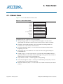
Appendix A. Frame Format
A.1. Ethernet Frame . . . . . . . . . . . . . . . . . . . . . . . . . . . . . . . . . . . . . . . . . . . . . . . . . . . . . . . . . . . . . . . . . . . .
A.2. VLAN and Stacked VLAN Tagged MAC Frame . . . . . . . . . . . . . . . . . . . . . . . . . . . . . . . . . . . . . . . .
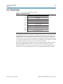
A.3. Pause Frame . . . . . . . . . . . . . . . . . . . . . . . . . . . . . . . . . . . . . . . . . . . . . . . . . . . . . . . . . . . . . . . . . . . . . . .
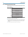
A.4. Priority-Based Flow Control Frame . . . . . . . . . . . . . . . . . . . . . . . . . . . . . . . . . . . . . . . . . . . . . . . . . . .
A–1
A–2
A–3
A–4
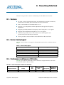
Appendix B. Time-of-Day (ToD) Clock
B.1. Features . . . . . . . . . . . . . . . . . . . . . . . . . . . . . . . . . . . . . . . . . . . . . . . . . . . . . . . . . . . . . . . . . . . . . . . . . . .
B.2. Device Family Support . . . . . . . . . . . . . . . . . . . . . . . . . . . . . . . . . . . . . . . . . . . . . . . . . . . . . . . . . . . . . .
B.3. Performance and Resource Utilization . . . . . . . . . . . . . . . . . . . . . . . . . . . . . . . . . . . . . . . . . . . . . . . . .
B.4. Parameter Setting . . . . . . . . . . . . . . . . . . . . . . . . . . . . . . . . . . . . . . . . . . . . . . . . . . . . . . . . . . . . . . . . . . .
B.5. ToD Clock Interface Signals . . . . . . . . . . . . . . . . . . . . . . . . . . . . . . . . . . . . . . . . . . . . . . . . . . . . . . . . . .
B.5.1. Avalon-MM Control Interface Signal . . . . . . . . . . . . . . . . . . . . . . . . . . . . . . . . . . . . . . . . . . . . . .
B.5.2. Avalon-ST Transmit Interface Signal . . . . . . . . . . . . . . . . . . . . . . . . . . . . . . . . . . . . . . . . . . . . . .
B.6. ToD Clock Configuration Register Space . . . . . . . . . . . . . . . . . . . . . . . . . . . . . . . . . . . . . . . . . . . . . . .
B.6.1. Adjusting ToD’s Drift . . . . . . . . . . . . . . . . . . . . . . . . . . . . . . . . . . . . . . . . . . . . . . . . . . . . . . . . . . .
B–1
B–1
B–1
B–2
B–2
B–3
B–3
B–4
B–5
Appendix C. Packet Classifier
C.1. Block Diagram . . . . . . . . . . . . . . . . . . . . . . . . . . . . . . . . . . . . . . . . . . . . . . . . . . . . . . . . . . . . . . . . . . . . .
C.2. Packet Classifier Signals . . . . . . . . . . . . . . . . . . . . . . . . . . . . . . . . . . . . . . . . . . . . . . . . . . . . . . . . . . . . .
C.2.1. Common Clock and Reset Signals . . . . . . . . . . . . . . . . . . . . . . . . . . . . . . . . . . . . . . . . . . . . . . . . .
C.2.2. Avalon-ST Interface Signals . . . . . . . . . . . . . . . . . . . . . . . . . . . . . . . . . . . . . . . . . . . . . . . . . . . . . .
C.2.3. Ingress Control Signals . . . . . . . . . . . . . . . . . . . . . . . . . . . . . . . . . . . . . . . . . . . . . . . . . . . . . . . . . .
C.2.4. Control Insert Signals . . . . . . . . . . . . . . . . . . . . . . . . . . . . . . . . . . . . . . . . . . . . . . . . . . . . . . . . . . .
C.2.5. Timestamp Field Location Signals . . . . . . . . . . . . . . . . . . . . . . . . . . . . . . . . . . . . . . . . . . . . . . . .
C–1
C–2
C–2
C–2
C–3
C–4
C–4
Appendix D. ToD Synchronizer
D.1. Device Family Support . . . . . . . . . . . . . . . . . . . . . . . . . . . . . . . . . . . . . . . . . . . . . . . . . . . . . . . . . . . . . .
D.2. Block Diagram . . . . . . . . . . . . . . . . . . . . . . . . . . . . . . . . . . . . . . . . . . . . . . . . . . . . . . . . . . . . . . . . . . . . .
D.3. ToD Synchronizer Parameter Settings . . . . . . . . . . . . . . . . . . . . . . . . . . . . . . . . . . . . . . . . . . . . . . . . .
D.4. ToD Synchronizer Signals . . . . . . . . . . . . . . . . . . . . . . . . . . . . . . . . . . . . . . . . . . . . . . . . . . . . . . . . . . .
D.4.1. Common Clock and Reset Signals . . . . . . . . . . . . . . . . . . . . . . . . . . . . . . . . . . . . . . . . . . . . . . . .
D.4.2. Interface Signals . . . . . . . . . . . . . . . . . . . . . . . . . . . . . . . . . . . . . . . . . . . . . . . . . . . . . . . . . . . . . . . .
D–1
D–2
D–3
D–4
D–4
D–4
Additional Information
Document Revision History . . . . . . . . . . . . . . . . . . . . . . . . . . . . . . . . . . . . . . . . . . . . . . . . . . . . . . . . . . . Info–1
How to Contact Altera . . . . . . . . . . . . . . . . . . . . . . . . . . . . . . . . . . . . . . . . . . . . . . . . . . . . . . . . . . . . . . . . Info–4
Typographic Conventions . . . . . . . . . . . . . . . . . . . . . . . . . . . . . . . . . . . . . . . . . . . . . . . . . . . . . . . . . . . . . Info–4
10-Gbps Ethernet MAC MegaCore Function User Guide
August 2014 Altera Corporation
1. About This IP Core
The 10-Gbps Ethernet (10GbE) Media Access Controller (MAC) IP core is a
configurable component that implements the IEEE 802.3-2008 specification. The IP
core offers the following modes:
■
10 Gbps mode—uses the Avalon® Streaming (Avalon-ST) interface on the client
side and the single data rate (SDR) XGMII on the network side.
■
1 Gbps/10 Gbps mode— uses the Avalon-ST interface on the client side and
GMII/SDR XGMII on the network side.
■
10 Mbps/100 Mbps/1 Gbps/10 Gbps (10M-10G) mode—uses the Avalon-ST
interface on the client side and MII/GMII/SDR XGMII on the network side.
To build a complete Ethernet subsystem in an Altera® device and connect it to an
external device, you can use the 10GbE MAC IP core with an Altera PHY IP core such
as a soft XAUI PHY in FPGA fabric, hard silicon-integrated XAUI PHY, a 10GBASE-R
PHY, a Backplane Ethernet 10GBASE-KR PHY, or a 1G/10 Gbps Ethernet PHY IP.
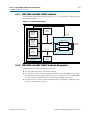
Figure 1–1 illustrates a system with the 10GbE MAC IP core.
Figure 1–1. Typical Application of 10GbE MAC
Altera FPGA
XAUI or
10GbE MAC or
10GBASE-R or
Client
Module
Avalon-ST
Interface
1G/10GbE MAC or
10M/100M/
1000M/10GbE MAC
SDR XGMII/
GMII/MII
Backplane Ethernet
10GBASE-KR PHY or
Serial
Interface
External PHY
1G/10Gbps Ethernet
1.1. Features
The 10GbE MAC supports the following features:
August 2014
■
Operating modes: 10 Mbps, 100 Mbps, 1 Gbps and 10 Gbps.
■
Support for full duplex only.
■
Avalon-ST 64-bit wide client interface running at 156.25 MHz.
■
Direct interface to 4-bit MII running at 125 MHZ with clock enable; 2.5 MHz for
10 Mbps and 25 MHz for 100 Mbps.
■
Direct interface to 8-bit GMII running at 125 MHZ.
■
Direct interface to 64-bit SDR XGMII running at 156.25 MHZ.
■
Virtual local area network (VLAN) and stacked VLAN tagged frames filtering as
specified by IEEE 802.IQ and 802.1ad (Q-in-Q) standards respectively.
Altera Corporation
10-Gbps Ethernet MAC MegaCore Function User Guide
1–2
Chapter 1: About This IP Core
Release Information
■
Optional cyclic redundancy code (CRC)-32 computation and insertion on the
transmit datapath; CRC checking on the receive datapath with optional
forwarding of the frame check sequence (FCS) field to the client application.
■
Checking of receive frames for FCS error, undersized and oversized frames, and
payload length error.
■
Deficit idle counter (DIC) for optimized performance with average inter-packet
gap (IPG) of 12 bytes for LAN applications.
■
Optional statistics collection on the transmit and receive datapaths.
■
Packets termination when the transmit datapath receives incomplete packets.
■
Programmable maximum length of transmit and receive frames up to
64 Kbytes (KB).
■
Programmable promiscuous (transparent) mode.
■
Optional Ethernet flow control and priority-based flow control (PFC) using pause
frames with programmable pause quanta. The PFC supports up to 8 priority
queues.
■
Optional padding termination on the receive datapath and insertion on the
transmit datapath.
■
Design examples with optional loopback and testbench for design verification.
■
Optional preamble passthrough mode on the transmit and receive datapaths. The
preamble passthrough mode allows you to define the preamble in the client frame.
■
Programmable datapath option to allow separate instantiation of MAC TX block,
MAC RX block, or both MAC TX and MAC RX blocks.
■
Optional IEEE 1588v2 feature for the following configurations:
■
10GbE MAC with 10GBASE-R PHY MegaCore function
■
1G/10GbE MAC with Backplane Ethernet 10GBASE-KR PHY MegaCore
function
■
Multi-speed 10M-10GbE MAC with Backplane Ethernet 10GBASE-KR PHY
MegaCore function
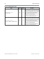
1.2. Release Information
Table 1–1 lists information about this release of the 10GbE MAC IP core.
Table 1–1. Release Information
Item
Version
Release Date
Ordering Code
Description
14.0
June 2014
IP-10GETHMAC
Product ID
ID 00D9
Vendor ID
6AF7
10-Gbps Ethernet MAC MegaCore Function User Guide
August 2014 Altera Corporation
Chapter 1: About This IP Core
Device Family Support
1–3
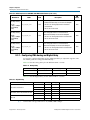
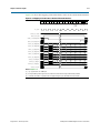
1.3. Device Family Support
f For new additions and enhancements to the latest Quartus II software and Altera IP,
refer to the What’s New for Altera IP page of the Altera website.
f For a list of IP support for all device families, refer to the All Intellectual Property
page of the Altera website.
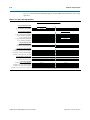
Table 1–2 shows the devices supported by the different configurations.
Table 1–2. Device Family Support for Configurations
Configuration
Arria V GT
Arria V GZ
Stratix V
Multi-Speed 10M-10GbE MAC
—
v
v
Multi-Speed 10M-10GbE MAC with IEEE 1588v2
—
v
v
10GbE MAC with 10GBASE-R PHY
v
v
v
v (1)
v
v
Multi-Speed 10M-10GbE MAC with Backplane
Ethernet 10GBASE-KR PHY
—
v
v
Multi-Speed 10M-10GbE MAC with Backplane
Ethernet 10GBASE-KR PHY and IEEE 1588v2
—
—
—
Multi-Speed 10M-10GbE MAC with 1G/10Gbps
Ethernet PHY
—
v
v
Multi-Speed 10M-10GbE MAC with 1G/10Gbps
Ethernet PHY and IEEE 1588v2
—
v
v
10GbE MAC with 10GBASE-R PHY and IEEE
1588v2
Note for Table 1–2:
(1) Supports only Arria V GT devices with speed grade of 3_H3.
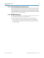
1.4. IP Core Verification
To ensure compliance with the IEEE specification, Altera performs extensive
validation of the 10GbE MAC IP core. Validation includes both simulation and
hardware testing.
1.4.1. Simulation Environment
Altera performs the following tests in the simulation environment:
August 2014
■
Directed tests that test all types and sizes of transaction layer packets and all bits of
the configuration space.
■
Error injection tests that inject errors in the link, transaction layer packets, and data
link layer packets, and check for the proper response from the IP core.
■
Random tests that test a wide range of traffic patterns across one or more virtual
channels.
Altera Corporation
10-Gbps Ethernet MAC MegaCore Function User Guide
1–4
Chapter 1: About This IP Core
Performance and Resource Utilization
1.4.2. Compatibility Testing Environment
Altera has performed significant hardware testing of the 10GbE MAC IP core to
ensure a reliable solution. The IP core has been tested with the following devices:
■
Arria V, Stratix IV, and Stratix V
■
Soft XAUI PHY
■
Soft and hard 10GBASE-R PHY
■
Hard Backplane Ethernet 10GBASE-KR PHY
■
1G/10Gbps Ethernet PHY
The IP core has passed all interoperability tests conducted by the UNH. In addition,
Altera internally tests every release with the Spirent Ethernet and 10G testers.
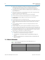
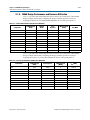
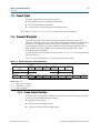
1.5. Performance and Resource Utilization
Table 1–3 provides the estimated performance and resource utilization of the 10GbE
MAC for the Cyclone IV device family. The estimates are obtained by compiling the
10GbE MAC with the Quartus II software targeting a Cyclone IV
(EP4CGX110DF31C7) device with speed grade –7.
1
To achieve your timing requirement in Quartus II, Altera recommends that you use
multiple seeds in the Design Space Explorer to find the optimal Fitter settings for your
design, follow the Timing Optimization Advisor's recommendations, apply the Speed
Optimization Technique and use the LogicLock regions.
Table 1–3. Cyclone IV Performance and Resource Utilization
Settings
All options disabled
All options enabled with
memory-based statistics counters
Logic Elements
Logic Registers
Memory Block (M9K)
fMAX (MHz)
4,424
3,245
2
>156.25
11,845
8,355
11
>156.25
Table 1–4 provides the estimated performance and resource utilization of the
10GbE MAC for the Stratix IV device family. The estimates are obtained by compiling
the 10GbE MAC with the Quartus II software targeting a Stratix IV GX
(EP4SGX70HF35C2) device with speed grade –2.
Table 1–4. Stratix IV Performance and Resource Utilization
Combinational ALUTs
Logic Registers
Memory Block (M9K)
fMAX (MHz)
1,954
3,157
0
>156.25
All options enabled with
memory-based statistics counters
5,684
8,349
7
>156.25
All options enabled with
register-based statistics counters
8,135
10,117
3
>156.25
Settings
All options disabled
10-Gbps Ethernet MAC MegaCore Function User Guide
August 2014 Altera Corporation
Chapter 1: About This IP Core
Performance and Resource Utilization
1–5
Table 1–5 provides the estimated performance and resource utilization of the
10GbE MAC for the Cyclone V device family. The estimates are obtained by compiling
the 10GbE MAC with the Quartus II software targeting a Cyclone V GX
(5CGXFC7D6F31C6) device with speed grade –6.
Table 1–5. Cyclone V Performance and Resource Utilization
Combinational ALUTs
Logic Registers
Memory Block (M10K)
fMAX (MHz)
2,322
3,444
2
>156.25
All options enabled with
memory-based statistics counters
4,417
5,464
6
>156.25
All options enabled with
register-based statistics counters
6,867
7,113
2
>156.25
Settings
All options disabled
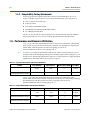
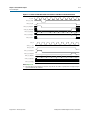
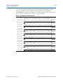
Table 1–6 provides the estimated performance and resource utilization of the
10GbE MAC for the Stratix V device family. The estimates are obtained by compiling
the 10GbE MAC with the Quartus II software targeting a Stratix V GX
(5SGXEA7H3F35C3) device with speed grade –3.
Table 1–6. Stratix V Performance and Resource Utilization for 10GbE MAC
Combinational ALUTs
Dedicated Logic
Registers
Memory Block (M20K)
fMAX (MHz)
2,001
3,077
0
>156.25
All options enabled with
memory-based statistics counters
5,772
8,197
7
>156.25
All options enabled with
register-based statistics counters
8,202
9,965
3
>156.25
4,827
5,921
8
>156.25
6,822
7,926
11
>156.25
Settings
All options disabled
IEEE 1588v2 feature enabled with
2-step synchronization
■
Timestamping is enabled
■
ptp_1step is disabled
IEEE 1588v2 feature enabled with
1-step and 2-step synchronization
■
Timestamping is enabled
■
ptp_1step is disabled
August 2014
Altera Corporation
10-Gbps Ethernet MAC MegaCore Function User Guide
1–6
Chapter 1: About This IP Core
Performance and Resource Utilization
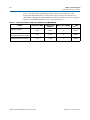
Table 1–7 provides the estimated performance and resource utilization of the
multi-speed 10M-10GbE MAC for the Stratix V device family. The estimates are
obtained by compiling the 10M-10GbE MAC with the Quartus II software targeting a
Stratix V GX (5SGXEA7H3F35C3) device with speed grade –3.
Table 1–7. Stratix V Performance and Resource Utilization for 10M-10GbE MAC
Combinational ALUTs
Dedicated Logic
Registers
Memory Block (M20K)
fMAX (MHz)
3,654
4,645
7
>156.25
All options enabled with
memory-based statistics counters
4,877
5,797
11
>156.25
All options enabled with
register-based statistics counters
7,313
7,544
7
>156.25
Settings
All options disabled
10-Gbps Ethernet MAC MegaCore Function User Guide
August 2014 Altera Corporation
2. Getting Started with Altera IP Cores
This chapter provides a general overview of the Altera IP core design flow to help you
quickly get started with any Altera IP core.
2.1. Introduction to Altera IP Cores
Altera® and strategic IP partners offer a broad portfolio of off-the-shelf, configurable
IP cores optimized for Altera devices. Altera delivers an IP core library with the
Quartus® II software. OpenCore Plus IP evaluation enables fast acquisition,
evaluation, and hardware testing of all Altera IP cores.
Nearly all complex FPGA designs include optimized logic from IP cores. You can
integrate optimized and verified IP cores into your design to shorten design cycles
and maximize performance. The Quartus II software includes the Altera IP Library,
and supports IP cores from other sources. You can define and generate a custom IP
variation to represent complex design logic in your project.
The Altera IP Library provides the following types of IP cores:
■
Basic functions
■
DSP functions
■
Interface protocols
■
Memory interfaces and controllers
■
Processors and peripherals
For more information about specific IP cores, refer to IP user guide documentation.
2.2. Installing and Licensing IP Cores
The Quartus II software includes the Altera IP Library. The library provides many
useful IP core functions for production use without additional license. You can fully
evaluate any licensed Altera IP core in simulation and in hardware until you are
satisfied with its functionality and performance.
Some Altera IP cores, such as MegaCore® functions, require that you purchase a
separate license for production use. After you purchase a license, visit the Self Service
Licensing Center to obtain a license number for any Altera product. For additional
information, refer to Altera Software Installation and Licensing.
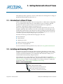
Figure 2–1. IP core Installation Path
acds
quartus - Contains the Quartus II software
ip - Contains the Altera IP Library and third-party IP cores
altera - Contains the Altera IP Library source code
<IP core name> - Contains the IP core source files
August 2014
Altera Corporation
10-Gbps Ethernet MAC MegaCore Function User Guide
2–2
Chapter 2: Getting Started with Altera IP Cores
IP Catalog and Parameter Editor
1
The default installation directory on Windows is <drive>:\altera\<version number>;
on Linux it is <home directory>/altera/<version number>.
2.2.1. OpenCore Plus IP Evaluation
Altera's free OpenCore Plus feature allows you to evaluate licensed MegaCore IP
cores in simulation and hardware before purchase. You need only purchase a license
for MegaCore IP cores if you decide to take your design to production. OpenCore Plus
supports the following evaluations:
■
Simulate the behavior of a licensed IP core in your system.
■
Verify the functionality, size, and speed of the IP core quickly and easily.
■
Generate time-limited device programming files for designs that include IP cores.
■
Program a device with your IP core and verify your design in hardware.
OpenCore Plus evaluation supports the following two operation modes:
■
Untethered—run the design containing the licensed IP for a limited time.
■
Tethered—run the design containing the licensed IP for a longer time or
indefinitely. This requires a connection between your board and the host
computer.
All IP cores using OpenCore Plus in a design time out simultaneously when any IP
core times out.
2.3. IP Catalog and Parameter Editor
The Quartus II IP Catalog (Tools > IP Catalog) and parameter editor help you easily
customize and integrate IP cores into your project. You can use the IP Catalog and
parameter editor to select, customize, and generate files representing your custom IP
variation.
The IP Catalog automatically displays the IP cores available for your target device.
Double-click any IP core name to launch the parameter editor and generate files
representing your IP variation. The parameter editor prompts you to specify your IP
variation name, optional ports, architecture features, and output file generation
options. The parameter editor generates a top-level .qsys or .qip file representing the
IP core in your project. Alternatively, you can define an IP variation without an open
Quartus II project. When no project is open, select the Device Family directly in IP
Catalog to filter IP cores by device.
1
The IP Catalog is also available in Qsys (View > IP Catalog). The Qsys IP Catalog
includes exclusive system interconnect, video and image processing, and other
system-level IP that are not available in the Quartus II IP Catalog.
Use the following features to help you quickly locate and select an IP core:
■
Filter IP Catalog to Show IP for active device family or Show IP for all device
families.
■
Search to locate any full or partial IP core name in IP Catalog. Click Search for
Partner IP, to access partner IP information on the Altera website.
10-Gbps Ethernet MAC MegaCore Function User Guide
August 2014 Altera Corporation
Chapter 2: Getting Started with Altera IP Cores
Using the Parameter Editor
■
2–3
Right-click an IP core name in IP Catalog to display details about supported
devices, installation location, and links to documentation.
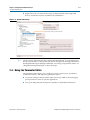
Figure 2–2. Quartus II IP Catalog
Search and filter IP for your target device
Double-click to customize, right-click for information
1
The IP Catalog and parameter editor replace the MegaWizard™ Plug-In Manager in
the Quartus II software. The Quartus II software may generate messages that refer to
the MegaWizard Plug-In Manager. Substitute “IP Catalog and parameter editor” for
“MegaWizard Plug-In Manager” in these messages.
2.4. Using the Parameter Editor
The parameter editor helps you to configure your IP variation ports, parameters,
architecture features, and output file generation options:
August 2014
■
Use preset settings in the parameter editor (where provided) to instantly apply
preset parameter values for specific applications.
■
View port and parameter descriptions and links to detailed documentation.
Altera Corporation
10-Gbps Ethernet MAC MegaCore Function User Guide
2–4
Chapter 2: Getting Started with Altera IP Cores
Customizing and Generating IP Cores
■
Generate testbench systems or example designs (where provided).
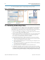
Figure 2–3. IP Parameter Editors
View IP port
and parameter
details
Legacy parameter
editors
Specify your IP variation name
and target device
Apply preset parameters for
specific applications
2.5. Customizing and Generating IP Cores
You can customize IP cores to support a wide variety of applications. The Quartus II
IP Catalog displays IP cores available for the current target device. The parameter
editor guides you to set parameter values for optional ports, features, and output files.
To customize and generate a custom IP core variation, follow these steps:
1. In the IP Catalog (Tools > IP Catalog), locate and double-click the name of the IP
core to customize. The parameter editor appears.
2. Specify a top-level name for your custom IP variation. This name identifies the IP
core variation files in your project. If prompted, also specify the target Altera
device family and output file HDL preference. Click OK.
3. Specify the desired parameters, output, and options for your IP core variation:
■
Optionally select preset parameter values. Presets specify all initial parameter
values for specific applications (where provided).
■
Specify parameters defining the IP core functionality, port configuration, and
device-specific features.
■
Specify options for generation of a timing netlist, simulation model, testbench,
or example design (where applicable).
■
Specify options for processing the IP core files in other EDA tools.
4. Click Finish or Generate to generate synthesis and other optional files matching
your IP variation specifications. The parameter editor generates the top-level .qip
or .qsys IP variation file and HDL files for synthesis and simulation. Some IP cores
also simultaneously generate a testbench or example design for hardware testing.
10-Gbps Ethernet MAC MegaCore Function User Guide
August 2014 Altera Corporation
Chapter 2: Getting Started with Altera IP Cores
Specifying the Parameters
2–5
When you generate the IP variation with a Quartus II project open, the parameter
editor automatically adds the IP variation to the project. Alternatively, click Project >
Add/Remove Files in Project to manually add a top-level .qip or .qsys IP variation
file to a Quartus II project. To fully integrate the IP into the design, make appropriate
pin assignments to connect ports. You can define a virtual pin to avoid making
specific pin assignments to top-level signals.
2.6. Specifying the Parameters
To specify parameters for your IP core using the Qsys flow, follow these steps:
1. Open an existing Quartus II project or create a new project using the New Project
Wizard available from the File menu.
2. On the Tools menu, click Qsys.
3. On the Component Library tab, expand the Interfaces Protocols list and then the
Ethernet list. Double-click Ethernet 10G MAC to add it to your system. The
relevant parameter editor appears.
4. Specify the required parameters in the Qsys tool. For detailed explanations of
these parameters, refer to “10GbE MAC Parameter Settings” on page 2–8.
5. Click Finish to complete the IP core instance and add it to the system.
2.7. Upgrading Outdated IP Cores
Altera IP cores have a version number that corresponds with the Quartus II software
version. The Quartus II software alerts you when your IP core is outdated with
respect to the current Quartus II software version. Click Project > Upgrade IP
Components to easily identify and upgrade outdated IP cores.
You are prompted to upgrade IP when the new version includes port, parameter, or
feature changes. You are also notified if IP is unsupported or cannot be migrated in
the current software. Most Altera IP cores support automatic simultaneous upgrade,
as indicated in the GUI. IP cores unsupported by auto upgrade require regeneration in
the parameter editor.
To upgrade outdated IP cores in your design, follow these steps:
1. In the latest version of the Quartus II software, open the Quartus II project
containing an outdated IP core variation.
2. Click Project > Upgrade IP Components. The Upgrade IP Components dialog
box displays all outdated IP cores in your project, along with basic instructions for
upgrading each core.
3. Upgrading IP cores changes your original design files. To preserve these original
files, click Project > Archive and save a project archive preserving your original
files.
4. To simultaneously upgrade all IP cores that support automatic upgrade, click
Perform Automatic Upgrade. The IP variation upgrades to the latest version.
August 2014
Altera Corporation
10-Gbps Ethernet MAC MegaCore Function User Guide
2–6
Chapter 2: Getting Started with Altera IP Cores
Simulating IP Cores
5. To upgrade IP cores unsupported by automatic upgrade, select the IP core in
Upgrade IP Components dialog box, and then click Upgrade in Editor. The
parameter editor appears. Click Finish or Generate to regenerate the IP variation
and complete the upgrade. The version number updates when complete.
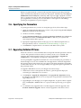
Figure 2–4. Upgrading Outdated IP Cores
Indicates that IP upgrade is:
Required
Optional
Complete
Unsupported
Displays upgrade
status for all IP cores
in the Project
Upgrades all IP core that support “Auto Upgrade”
Upgrades individual IP cores unsupported by “Auto Upgrade”
1
Altera verifies that the current version of the Quartus II software compiles the
previous version of each IP core. The MegaCore IP Library Release Notes and Errata
reports any verification exceptions. Altera does not verify compilation for IP cores
older than the previous release.
Alternatively, you can upgrade IP cores at the command line. To upgrade a single IP
core:
quartus_sh --ip_upgrade -variation_files <variation_file_path> <project>
To upgrade a list of IP cores:
quartus_sh --ip_upgrade -variation_files
<variation_file_path>;<qsys_file_path>;<variation_file_path> <project>
1
File paths must be relative to the project directory and you must reference
the IP variation .v or .vhd file or .qsys file, not the .qip file.
2.8. Simulating IP Cores
The Quartus II software supports RTL- and gate-level design simulation of Altera IP
cores in supported EDA simulators. Simulation involves setting up your simulator
working environment, compiling simulation model libraries, and running your
simulation.
You can use the functional simulation model and the testbench or example design
generated with your IP core for simulation. The functional simulation model and
testbench files are generated in a project subdirectory. This directory may also include
scripts to compile and run the testbench. For a complete list of models or libraries
required to simulate your IP core, refer to the scripts generated with the testbench.
You can use the Quartus II NativeLink feature to automatically generate simulation
files and scripts. NativeLink launches your preferred simulator from within the
Quartus II software.
10-Gbps Ethernet MAC MegaCore Function User Guide
August 2014 Altera Corporation
Chapter 2: Getting Started with Altera IP Cores
Simulating IP Cores
2–7
You can simulate the 10GbE MAC IP core with the functional simulation model
generated by the Quartus II software. To perform a successful simulation of the 10GbE
MAC IP core, you are required to compile all files listed in the
<project directory>/<variation name>_sim output file. Otherwise, the simulation may
fail.
f For more information about simulating Altera IP cores, refer to Simulating Altera
Designs in volume 3 of the Quartus II Handbook.
August 2014
Altera Corporation
10-Gbps Ethernet MAC MegaCore Function User Guide
2–8
Chapter 2: Getting Started with Altera IP Cores
10GbE MAC Parameter Settings
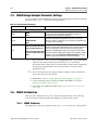
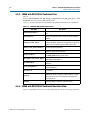
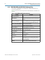
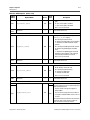
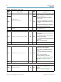
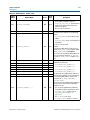
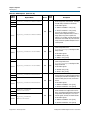
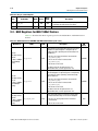
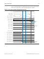
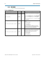
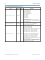
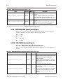
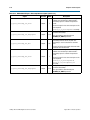
2.9. 10GbE MAC Parameter Settings
You customize the 10GbE MAC by specifying the parameters on the MegaWizard
Plug-in Manager, or Qsys in the Quartus II software. Table 2–1 describes the
parameters and how they affect the behavior of the IP core.
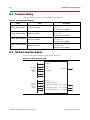
Table 2–1. 10GbE Parameters
Parameter
Speed
Enable preamble pass-through
mode
Description
Use this parameter to select the speed options. By default, the 10G MAC option is
selected. Select Enable 1G/10G MAC to implement the 10-Gbps and 1-Gbps MAC;
select Enable Multi-Speed 10M-10Gb MAC to implement the 10-Mbps, 100-Mbps, 1Gbps, and 10-Gbps MAC.
Turn on this parameter to enable the preamble passthrough mode. To enable the
preamble passthrough mode, you must turn on this parameter and set the
tx_preamble_control, rx_lane_decoder_preamble_control, and
rx_preamble_inserter_control registers to 1.
This parameter is disabled if you selected Enable 1G/10G MAC.
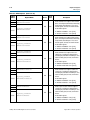
Enable priority-based flow control
(PFC)
Turn on this parameter to enable PFC. Refer to “Priority-Based Flow Control” on
page 7–20 for more information on PFC and its operations.
Number of PFC queues
Indicates the number of PFC priority levels that the 10GbE MAC IP core supports. The
valid range is from 2 to 8. This option is enabled only if you turn on the Priority-based
flow control (PFC) parameter.
Enable unidirectional mode
Turn on this parameter to enable unidirectional mode on transmit path for 10G. This
feature only works in 10G speed and in the transmit datapath.
Datapath option
Use this parameter to select the datapath option that determines the MAC variation to
instantiate. By default, the TX & RX option is selected. The default datapath
instantiates the MAC TX and MAC RX blocks. Selecting TX only instantiates the MAC
TX block; selecting RX only instantiates the MAC RX block.
Enable supplementary address
Turn on this parameter to enable supplementary addresses. To enable supplementary
addresses, you must turn on this parameter and set the EN_SUPP0/1/2/3 bits in the
rx_frame_control register to 1.
Enable CRC on transmit path
Turn on this parameter to calculate and insert CRC on the transmit datapath. To
compute and insert CRC on the transmit datapath, you must turn on this parameter
and set the tx_crcins_control[1] register bit to 1.
Enable statistics collection
Turn on this parameter to collect statistics on the transmit and receive datapaths.
When you turn on Statistics collection, the default implementation of the statistics
counters is Memory-based.
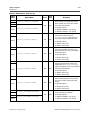
Statistics counters
Use Memory-based statistics counters to free up the logic elements (the MAC does
not clear the statistic counters after the counters are read); Register-based statistics
counters to free up the memory (the MAC clears the statistic counters after the
counters are read).
Register-based statistics counters are not supported for Cyclone IV GX devices.
Enable time stamping
Enable PTP 1-step clock support
Turn on this parameter to enable time stamping on the transmitted and received
frames.
Turn on this parameter to insert time stamp on PTP messages for 1-step clock based
on the TX Egress Timestamp Insert Control interface.
This parameter is disabled if you do not turn on Enable time stamping.
Timestamp fingerprint width
Use this parameter to set the width in bits for the time stamp fingerprint on the TX
path. The default value is 4 bits.
10-Gbps Ethernet MAC MegaCore Function User Guide
August 2014 Altera Corporation
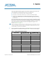
3. 10GbE MAC Design Examples
You can use the following 10GbE design examples and testbenches to help you get
started with the 10GbE MAC IP core and use the core in your design:
1
■
10GbE MAC with XAUI PHY
■
10GbE MAC with 10GBASE-R PHY
XAUI PHY and 10GBASE-R PHY do not support Stratix III devices.
3.1. Software and Hardware Requirements
Altera uses the following hardware and software to test the 10GbE design examples
and testbenches:
■
Quartus II software 14.0
■
Stratix IV GX FPGA development kit (for XAUI PHY)
■
Transceiver Signal Integrity development kit, Stratix IV GT Edition (for
10GBASE-R PHY)
■
ModelSim®-AE 6.6c, ModelSim-SE 6.6c or higher
f For more information on the development kits, refer to the following documents:
August 2014
■
Stratix IV GX Development Kit User Guide
■
Stratix IV GX Development Kit Reference Manual
■
Transceiver Signal Integrity Development Kit, Stratix IV GT Edition User Guide
■
Transceiver Signal Integrity Development Kit, Stratix IV GT Edition Reference Manual
Altera Corporation
10-Gbps Ethernet MAC MegaCore Function User Guide
3–2
Chapter 3: 10GbE MAC Design Examples
10GbE Design Example Components
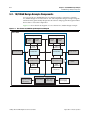
3.2. 10GbE Design Example Components
You can use the 10GbE MAC IP core design example to simulate a complete 10GbE
design in an Altera FPGA. You can compile the design example using the simulation
files generated by the Quartus II software and program the targeted Altera device
after a successful compilation.
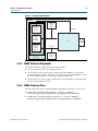
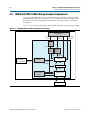
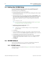
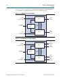
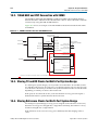
Figure 3–1 shows the block diagram of the 10GbE design examples.
Figure 3–1. 10GbE Design Example Block Diagram
Altera FPGA
Client
Application
64-bit Avalon-ST
Avalon-ST
64
Single-Clock / Dual-Clock
FIFO
64
Design Example
Rx FIFO Buffer
64
Tx FIFO Buffer
64-bit Avalon-ST 64
Configuration and Debugging Tools
10GbE MAC
Pipeline Bridge
32
32
32-bit Avalon-MM
Client Application
(Configuration, Status, and
Statistics)
32-bit
Avalon-MM
72
72-bit SDR XGMII 72
JTAG to Avalon Master
Bridge
Ethernet
Loopback
72
MDIO
72-bit SDR XGMII 72
XAUI
or
10GBASE-R
PHY
XAUI / 10GBASE-R
System Console
(for debugging)
10-Gbps Ethernet MAC MegaCore Function User Guide
MDIO Signals
External
PHY
August 2014 Altera Corporation
Chapter 3: 10GbE MAC Design Examples
10GbE Design Example Components
3–3
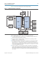
The design example comprises the following components:
■
10GbE Ethernet MAC—the MAC IP core with default settings. This IP core
includes memory-based statistics counters.
■
XAUI PHY or 10GBASE-R PHY—the PHY IP core with default settings. The XAUI
PHY is set to Hard XAUI by default.
■
Ethernet Loopback— the loopback module provides a mechanism for you to
verify the functionality of the MAC and PHY. Refer to Section 3.2.0.1, Ethernet
Loopback Module for more information about this module.
■
RX and TX FIFO buffers—Avalon-ST Single-Clock or Dual-Clock FIFO cores that
buffer receive and transmit data between the MAC and client. These FIFO buffers
are 64 bits wide and 512 bits deep. The default configuration is Avalon-ST
Single-Clock FIFO, which operates in store and forward mode and you can
configure it to provide packet-based flushing when an error occurs.
1
■
To enable the Avalon-ST Single-Clock FIFO to operate in cut through mode,
turn off the Use store and forward parameter in the Avalon-ST Single
Clock FIFO parameter editor.
Configuration and debugging tools—provides access to the registers of the
following components via the Avalon Memory-Mapped (Avalon-MM) interface:
MAC, MDIO, Ethernet loopback, PHY, and FIFO buffers. The provided testbench
includes an Avalon driver which uses the pipeline bridge to access the registers.
You can use the system console to access the registers via the JTAG to Avalon
Master Bridge core when verifying the design in the hardware.
f To learn more about the components, refer to the respective documents:
■
XAUI PHY and 10GBASE-R PHY, refer to Altera Transceiver PHY IP Core User
Guide.
■
Avalon-ST Single-Clock or Dual-Clock FIFO, JTAG to Avalon Master Bridge, and
MDIO cores, refer to Embedded Peripherals IP User Guide.
■
Pipeline bridge, refer to Avalon Memory-Mapped Bridges in volume 4 of the Quartus
II Handbook.
■
System Console, refer to Analyzing and Debugging Designs with the System Console in
volume 3 of the Quartus II Handbook.
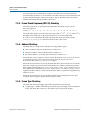
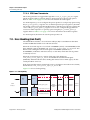
3.2.0.1. Ethernet Loopback Module
You can enable one of the following loopback types:
■
August 2014
Local loopback—turn on this loopback to verify the functionality of the MAC
during simulation. When you enable the local loopback, the Ethernet loopback
module takes the transmit frame from the MAC XGMII TX and loops it back to the
MAC XGMII RX datapath. During this cycle, the loopback module also forwards
the TX frame to the PHY. While the local loopback is turned on, the loopback
module ignores any frame it receives from the PHY.
Altera Corporation
10-Gbps Ethernet MAC MegaCore Function User Guide
3–4
Chapter 3: 10GbE MAC Design Examples
10GbE Design Example Components
■
Line loopback—turn on this loopback to verify the functionality of the PHY when
verifying the design example in hardware. When you enable the line loopback, the
Ethernet loopback module takes the XGMII RX signal received from the PHY and
loops it back to the PHY’s XGMII TX signal. During this cycle, the loopback
module also forwards the XGMII RX signal to the MAC. While the line loopback is
turned on, the loopback module ignores any frame transmitted from the MAC.
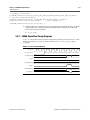
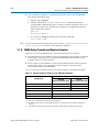
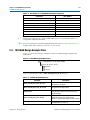
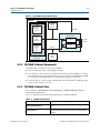
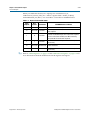
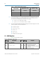
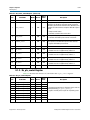
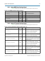
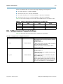
Table 3–1 describes the registers you can use to enable or disable the desired loopback.
Table 3–1. Loopback Registers
Byte Offset
Register
0x00
line loopback
0x04
Reserved
0x08
local loopback
Description
Set this register to 1 to enable line loopback; 0 to disable it.
—
Set this register to 1 to enable local loopback; 0 to disable it.
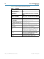
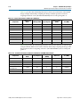
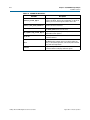
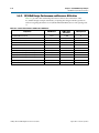
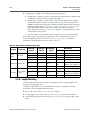
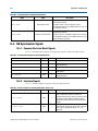
3.2.0.2. Base Addresses
Table 3–2 lists the design example components that you can reconfigure to suit your
verification objectives. To reconfigure the components, write to their registers using
the base addresses listed in the table and the register offsets described in the
components' user guides. Refer to Table 3–1 for the Ethernet loopback registers.
Table 3–2. Base Addresses of Design Example Components
Component
10GbE MAC
1
Base Address
0x000
XAUI or 10GBASE-R PHY
0x40000
MDIO
0X10000
Ethernet loopback
0x10200
RX FIFO (Avalon-ST Single-Clock FIFO)
0x10400
TX FIFO (Avalon-ST Single-Clock FIFO)
0x10600
This design example uses a 19-bit width address bus to access the base address of
components other than the MAC.
10-Gbps Ethernet MAC MegaCore Function User Guide
August 2014 Altera Corporation
Chapter 3: 10GbE MAC Design Examples
10GbE Design Example Files
3–5
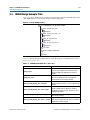
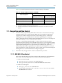
3.3. 10GbE Design Example Files
Figure 3–2 shows the directory structure for the design examples and testbenches. The
..\csr_script directory contains the design example script files.
Figure 3–2. Design Example Folders
<ip_lib>/ethernet/altera_eth_10g_design_example
altera_eth_10g_mac_base_r
testbench
altera_eth_10g_mac_base_r_sv
testbench
altera_eth_10g_mac_xaui
testbench
altera_eth_10g_mac_xaui_sv
testbench
csr_scripts
design_example_components
source
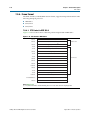
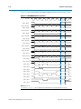
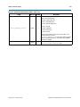
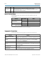
Table 3–3 lists the design example files. For the description of testbench files, refer to
Table 3–5 on page 3–10.
Table 3–3. 10GbE Design Example Files (Part 1 of 2)
File Name
August 2014
Description
setup_proj.tcl
A Tcl script that creates a new Quartus II project
and sets up the project environment for your
design example. Not applicable for Stratix V
design.
setup_proj_sv.tcl
A Tcl script that creates a new Quartus II project
for Stratix V design and sets up the project
environment for your design example.
altera_eth_10g_design_mac_xaui.qsys
A Qsys file for the 10GbE MAC and XAUI PHY
design example. The PHY is set to hard XAUI by
default.
altera_eth_10g_design_mac_xaui_sv.qsys
A Qsys file for the 10GbE MAC and XAUI PHY
design example with the Quartus II software
targeting the Stratix V device. The PHY is set to
hard XAUI by default.
altera_eth_10g_design_mac_base_r.qsys
A Qsys file for the 10GbE MAC and 10GBASE-R
PHY design example.
altera_eth_10g_design_mac_base_r_sv.qsys
A Qsys file for the 10GbE MAC and 10GBASE-R
PHY design example with the Quartus II software
targeting the Stratix V device.
Altera Corporation
10-Gbps Ethernet MAC MegaCore Function User Guide
3–6
Chapter 3: 10GbE MAC Design Examples
Creating a New 10GbE Design
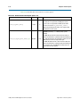
Table 3–3. 10GbE Design Example Files (Part 2 of 2)
File Name
Description
setup_SIVGX230C2ES.tcl
A Tcl script that sets the pin assignments and I/O
standards for the Stratix IV GX FPGA
development board. Use this Tcl script for the
10GbE MAC with XAUI PHY design example.
setup_EP4S100G5H40I3.tcl
A Tcl script that sets the pin assignments and I/O
standards for the Stratix IV GT Signal Integrity
development board. Use this Tcl script for the
10GbE MAC with 10GBASE-R PHY design
example.
setup_5SGXEA7N2F40C2ES.tcl
A Tcl script that sets the pin assignments and I/O
standards for the Stratix V GX Signal Integrity
development board. Use this Tcl script for the
10GbE MAC with 10GBASE-R PHY design
example.
top.sdc
The Quartus II SDC constraint file for use with
the TimeQuest timing analyzer.
top.v
The top-level entity file of the design example for
verification in hardware. Not applicable for
Stratix V design.
top_sv.v
The top-level entity file of the design example—
with the Quartus II software targeting the
Stratix V device—for verification in hardware.
common.tcl
A Tcl script that contains basic functions based
on the system console APIs to access the
registers through the Avalon-MM interface.
config.tcl
A Tcl script that configures the design example.
csr_pkg.tcl
A Tcl script that maps address to the Avalon-MM
control registers. The script contains APIs which
is used by config.tcl and show_stats.tcl.
show_stats.tcl
A Tcl script that displays the MAC statistics
counters.
altera_eth_10g_design_example_hw.tcl
A hardware Tcl script that contains the
composition of the Ethernet system.
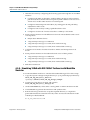
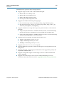
3.4. Creating a New 10GbE Design
You can use the Quartus II software to create a new 10GbE design. Altera provides a
customizable Qsys design example file to facilitate the development of your 10GbE
design. Follow these steps to create the design:
1. Copy the respective design example directory to your preferred project directory:
altera_eth_10g_mac_xaui or altera_eth_10g_mac_base_r from
<ip library>/ethernet/altera_eth_10g_design_example.
2. Launch the Quartus II software and open the top.v file from the project directory.
10-Gbps Ethernet MAC MegaCore Function User Guide
August 2014 Altera Corporation
Chapter 3: 10GbE MAC Design Examples
Creating a New 10GbE Design
3–7
3. Open the Quartus II Tcl Console window by pointing to Utility Windows on the
View menu and then selecting Tcl Console. In the Quartus II Tcl Console window,
type the following command to set up the project environment:
source setup_proj.tclr
4. Load the pin assignments and I/O standards for the development board:
■
For the 10GbE MAC with XAUI PHY design example, type the following
command:
source setup_SIVGX230C2ES.tclr
This command assigns the XAUI serial interface to the pins that are connected
to the HSMC Port A of the Stratix IV GX development board.
■
For the 10GbE MAC with 10GBASE-R design example, type the following
command:
source setup_EP4S100G2F40I1.tclr
This command assigns the 10GBASE-R serial interface to the pins that are
connected to the SMA connectors (J38 to J41) of the Stratix IV GT development
board.
f For more information about the development boards, refer to the respective
reference manuals: Stratix IV GX Development Kit Reference Manual or
Transceiver Signal Integrity Development kit, Stratix IV GT Edition Reference
Manual.
5. Launch Qsys from the Tools menu and open the altera_eth_10g_mac_base_r.qsys
or altera_eth_10g_mac_xaui.qsys file. For design targeting the Stratix V device
family, use the altera_eth_10g_mac_base_r_sv.qsys or
altera_eth_10g_mac_xaui_sv.qsys file.
1
By default, the design example targets the Stratix IV device family. To
change the target device family, click on the Project Settings tab and select
the desired device from the Device family list.
6. Turn off the additional module under the Use column if your design does not
require them. This action disconnects the module from the 10GbE system.
7. Double-click eth_10g_design_example_0 to launch the parameter editor.
8. Specify the required parameters in the parameter editor. For detailed explanations
of these parameters, refer to “10GbE Design Example Parameter Settings” on
page 3–8.
9. Click Finish.
10. On the Generation tab, select either a Verilog HDL or a VHDL simulation model
and make sure that the Create HDL design files for synthesis option is turned on.
11. Click Generate to generate the simulation and synthesis files.
August 2014
Altera Corporation
10-Gbps Ethernet MAC MegaCore Function User Guide
3–8
Chapter 3: 10GbE MAC Design Examples
10GbE Design Example Parameter Settings
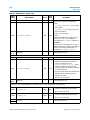
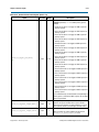
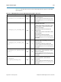
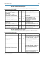
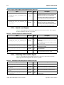
3.5. 10GbE Design Example Parameter Settings
You can customize the 10GbE design example by specifying the parameters using the
parameter editor. Table 3–4 describes these parameters.
Table 3–4. Design Example Parameters
Name
Value
Description
Configuration
MDIO
Specifies whether the Ethernet system requires a MDIO core to
access the external PHY device management registers for
configuration and management purposes.
MDIO
None
XAUI PHY
PHY IP
10GBase-R PHY
None
Avalon-ST Single Clock FIFO
Avalon-ST Dual Clock FIFO
FIFO
Avalon-ST Single Clock FIFO
+ Avalon-ST Dual Clock FIFO
None
1
Specifies which protocol-specific PHY IP core to use for the
Ethernet system. For XAUI PHY, you can choose to implement the
system in soft or hard logic.
Specifies which FIFO buffer to use for the Ethernet system. The
Avalon-ST Single Clock FIFO operates with a common clock for the
input and output ports while the Avalon-ST Dual Clock FIFO
operates with independent clocks for the input and output ports.
You cannot enable a different FIFO option for TX datapath and RX
datapath. If you select Avalon-ST Single Clock FIFO, the design
includes single clock FIFO at both TX and RX datapaths.
The parameter values you select on Configuration tab correspond with the
other tabs that require further parameterization. You should only
parameterize the components you selected and omit the others. Editing the
component parameters that were not selected may cause the system
generation to fail.
f For more information about the parameter settings of other components,
refer to the respective documents:
■
10GbE MAC, refer to “10GbE MAC Parameter Settings” on page 2–8.
■
Avalon-ST Single-Clock or Dual-Clock FIFO and MDIO core, refer to
Embedded Peripherals IP User Guide.
■
XAUI PHY and 10GBASE-R PHY, refer to Altera Transceiver PHY IP Core
User Guide.
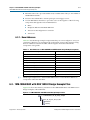
3.6. 10GbE Testbenches
Altera provides testbenches for you to verify the design examples. The following
sections in this document describe the testbench, its components, and use.
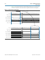
3.6.1. 10GbE Testbench
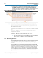
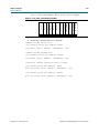
The testbenches operate in loopback mode. Figure 3–3 shows the flow of the packets.
10-Gbps Ethernet MAC MegaCore Function User Guide
August 2014 Altera Corporation
Chapter 3: 10GbE MAC Design Examples
10GbE Testbenches
3–9
Figure 3–3. Testbench Block Diagram
Testbench
Avalon-MM
Control
Register
Avalon-ST
Transmit
Frame
Generator
Avalon-ST
Receive
Frame
Monitor
avalon_bfm_wrapper.sv
Avalon Driver
Ethernet
Packet
Monitor
Avalon-MM
Avalon-ST
DUT
Loopback
on XGMII
Avalon-ST
Ethernet
Packet
Monitor
3.6.2. 10GbE Testbench Component
The 10GbE testbench comprises the following modules:
■
Device under test (DUT)—the design example.
■
Avalon driver—uses Avalon-ST bus functional models (BFMs) to exercise the
transmit and receive paths. The driver also utilizes the Avalon-MM BFM to access
the Avalon-MM interfaces of the design example components.
■
Packet monitors—monitors the transmit and receive datapaths, and displays the
frames in the simulator console.
3.6.3. 10GbE Testbench Files
The following directories contain the 10GbE testbench files which are in clear text:
August 2014
■
10GbE MAC and XAUI PHY testbench—<ip library>/ethernet/
altera_eth_10g_design_example/altera_eth_10g_mac_xaui/testbench
■
10GbE MAC and 10GBASE-R PHY testbench— <ip library>/ethernet/
altera_eth_10g_design_example/altera_eth_10g_mac_base_r/testbench
Altera Corporation
10-Gbps Ethernet MAC MegaCore Function User Guide
3–10
Chapter 3: 10GbE MAC Design Examples
10GbE Testbenches
Table 3–5 describes the files that implement the testbench.
Table 3–5. Testbench Files
File Name
Description
avalon_bfm_wrapper.sv
A wrapper for the Avalon BFMs that the avalon_driver.sv file
uses.
avalon_driver.sv
A SystemVerilog HDL driver that utilizes the BFMs to exercise
the transmit and receive path, and access the Avalon-MM
interface.
avalon_if_params_pkg.sv
A SystemVerilog HDL testbench that contains parameters to
configure the BFMs. Because the configuration is specific to
the DUT, you must not change the contents of this file.
avalon_st_eth_packet_monitor.sv
A SystemVerilog HDL testbench that monitors the Avalon-ST
transmit and receive interfaces.
eth_mac_frame.sv
A SystemVerilog HDL class that defines the Ethernet frames.
The avalon_driver.sv file uses this class.
eth_register_map_params_pkg.sv
A SystemVerilog HDL package that maps addresses to the
Avalon-MM control registers.
tb_run.tcl
A Tcl script that starts a simulation session in the ModelSim
simulation software. Not applicable for Stratix V design.
tb_run_sv.tcl
A Tcl script that starts a simulation session in the ModelSim
simulation software for Stratix V design only.
tb.sv
The top-level testbench file. This file includes the customized
10GbE MAC which is the device under test (DUT), a client
packet generator, and a client packet monitor along with
other logic blocks. Not applicable for Stratix V design.
tb_sv.sv
The top-level testbench file for Stratix V design only. This file
includes the customized 10GbE MAC which is the device
under test (DUT), a client packet generator, and a client
packet monitor along with other logic blocks.
wave.do
A signal tracing macro script to be used with the ModelSim
simulation software to display testbench signals.
10-Gbps Ethernet MAC MegaCore Function User Guide
August 2014 Altera Corporation
Chapter 3: 10GbE MAC Design Examples
10GbE Testbenches
3–11
3.6.4. 10GbE Testbench Simulation Flow
Upon a simulated power-on reset, each testbench performs the following operations:
1. Initializes the DUT by configuring the following options via the Avalon-MM
interface:
a. In the MAC, enables address insertion on the transmit path and sets the
transmit primary MAC address to EE-CC-88-CC-AA-EE.
b. In the TX and RX FIFO (Avalon-ST Single Clock FIFO core), enables drop on
error.
2. Starts packet transmission. The testbench sends a total of eight packets:
a. 64-byte basic Ethernet frame
b. Pause frame
c. 1518-byte VLAN frame
d. 1518-byte basic Ethernet frame
e. 64-byte stacked VLAN frame
f. 500-byte VLAN frame
g. Pause frame
h. 1518-byte stacked VLAN frame
3. Ends the transmission and displays the MAC statistics in the transcript pane.
3.6.5. Simulating the 10GbE Testbench with the ModelSim Simulator
To use the ModelSim simulator to simulate the testbench design, follow these steps:
1. Copy the respective design example directory to your preferred project directory:
altera_eth_10g_mac_xaui or altera_eth_10g_mac_base_r from
<ip library>/ethernet/altera_eth_10g_design_example.
2. The design example and testbench files are set to read only. Altera recommends
that you turn off the read-only attribute of all design example and testbench files.
3. Launch the Quartus II software and open the top.v file from the project directory.
4. Open the Quartus II Tcl Console window by pointing to Utility Windows on the
View menu and then selecting Tcl Console. In the Quartus II Tcl Console window,
type the following command to set up the project environment:
source setup_proj.tclr
5. Launch Qsys from the Tools menu and open altera_eth_10g_mac_base_r.qsys or
altera_eth_10g_mac_xaui.qsys in the File menu.
6. For the 10GbE MAC with XAUI design example, the default setting of the XAUI
PHY is Hard XAUI. Follow these steps if you want to set the PHY to Soft XAUI:
a. Double-click the XAUI PHY module to open the parameter editor.
b. On the General Options tab, select Soft XAUI for XAUI Interface Type.
7. On the Generation tab, select Verilog simulation model.
August 2014
Altera Corporation
10-Gbps Ethernet MAC MegaCore Function User Guide
3–12
Chapter 3: 10GbE MAC Design Examples
10GbE Testbenches
8. Click Generate to generate the system.Launch the ModelSim simulator software.
9. Change the working directory to <project directory>/<design example
directory>/testbench in the File menu.
10. Run the following command to set up the required libraries, compile the
generated IP Functional simulation model, and exercise the simulation model with
the provided testbench:
do tb_run.tclr
The ModelSim transcript pane in Main window displays messages from the
testbench reflecting the current task being performed.
Upon a successful simulation, the simulator displays the following RX Statistics
and TX Statistics:
#
#
#
#
#
#
#
#
#
#
#
#
#
#
#
#
#
#
#
#
#
#
#
#
#
#
#
#
#
framesOK = 8
framesErr = 0
framesCRCErr = 0
octetsOK = 5138
pauseMACCtrlFrames = 2
ifErrors = 0
unicastFramesOK = 4
unicastFramesErr = 0
multicastFramesOK = 1
multicastFramesErr = 0
broadcastFramesOK = 1
broadcastFramesErr = 0
etherStatsOctets = 5310
etherStatsPkts = 8
etherStatsUndersizePkts = 0
etherStatsOversizePkts = 0
etherStatsPkts64Octets = 4
etherStatsPkts65to127Octets = 0
etherStatsPkts128to255Octets = 0
etherStatsPkts256to511Octet = 1
etherStatsPkts512to1023Octets = 0
etherStatsPkts1024to1518Octets = 3
etherStatsPkts1519OtoXOctets = 0
etherStatsFragments = 0
etherStatsJabbers = 0
etherStatsCRCErr = 0
unicastMACCtrlFrames = 1
multicastMACCtrlFrames = 1
broadcastMACCtrlFrames = 0
3.6.6. Enabling Local Loopback
You can turn on local loopback to verify the functionality of the MAC during
simulation. Follow these steps to enable local loopback:
1. Open the tb.sv file.
2. Insert the command U_AVALON_DRIVER.avalon_mm_csr_wr(offset,value) where
offset is the sum of the base address of the loopback module and the register offset,
and value is the value to write to the register.
3. Set value to 1 to enable local loopback; 0 to disable it. Altera recommends that you
insert the command after the command that configures the RX FIFO. For example,
the following code segment enables local loopback:
10-Gbps Ethernet MAC MegaCore Function User Guide
August 2014 Altera Corporation
Chapter 3: 10GbE MAC Design Examples
10GbE Testbenches
3–13
// Configure the RX FIFO
U_AVALON_DRIVER.avalon_mm_csr_wr(RX_FIFO_DROP_ON_ERROR_ADDR,RX_FIFO_DROP_ON_ERROR);
// Read the configured registers
U_AVALON_DRIVER.avalon_mm_csr_rd(RX_FIFO_DROP_ON_ERROR_ADDR, readdata);
$display("RX FIFO Drop on Error Enable
= %0d", readdata[0]);
U_AVALON_DRIVER.avalon_mm_csr_wr(32'h948, 1)
4. Run the following command again to reconfigure the loopback module, set up the
required libraries, compile the generated IP Functional simulation model, and
exercise the simulation model:
do tb_run.tclr
3.6.7. 10GbE Simulation Timing Diagrams
Figure 3–4 shows the reset and initial configuration sequence. The first read or write
transaction must be at least one clock cycle after the csr_reset_reset_n signal
completes.
Figure 3–4. Reset and Configuration
csr_clk_clk
csr_reset_reset_n
csr_address [18:0]
40084
csr_read
csr_readdata [31:0]
csr_write
csr_writedata [31:0]
00000002
csr_waitrequest
August 2014
Altera Corporation
10-Gbps Ethernet MAC MegaCore Function User Guide
3–14
Chapter 3: 10GbE MAC Design Examples
10GbE Testbenches
Figure 3–5 shows the transmission of the first 60-byte frame upon a successful reset
and initial configuration. The same frame is looped back to the receive datapath.
Figure 3–5. Frame Transmission and Reception
Loopback
tx_clk_clk
avalon_st_tx_ready
avalon_st_tx_valid
avalon_st_tx_startofpacket
avalon_st_tx_endofpacket
avalon_st_tx_data [63:0]
avalon_st_tx_empty [2:0]
0
4
0
avalon_st_tx_error
rx_clk_clk
avalon_st_rx_ready
avalon_st_rx_valid
avalon_st_rx_startofpacket
avalon_st_rx_endofpacket
avalon_st_rx_data [63:0]
avalon_st_rx_empty [2:0]
0
avalon_st_rx_error [5:0]
0
10-Gbps Ethernet MAC MegaCore Function User Guide
4
August 2014 Altera Corporation
Chapter 3: 10GbE MAC Design Examples
10GbE Design Example Compilation and Verification in Hardware
3–15
3.7. 10GbE Design Example Compilation and Verification in Hardware
Figure 3–6 shows the components in the top-level file provided with the 10GbE
design example.
Figure 3–6. 10GbE Top-Level Components
Altera Development Board
Address
Swapper
Avalon-ST
DUT
XAUI/
10GBASE-R
Remote
Partner
The address swapper swaps the destination address and source address in the receive
frame before sending the frame onto the transmit path. You must connect the DUT—
design example—to a remote partner that generates, transmits, and receives frames.
3.7.1. Compiling the 10GbE Design
You can use the Quartus II software to compile the design example and program the
targeted Altera device after a successful compilation.
Follow these steps to compile the design and program the device:
1. Copy the respective design example directory to your preferred project directory:
altera_eth_10g_mac_xaui or altera_eth_10g_mac_base_r from
<ip library>/ethernet/altera_eth_10g_design_example.
2. Launch the Quartus II software and open top.v from the project directory.
3. Open the Quartus II Tcl Console window by pointing to Utility Windows on the
View menu then clicking Tcl Console. In the Quartus II Tcl Console window, type
the following command to set up the project environment:
source setup_proj.tclr
August 2014
Altera Corporation
10-Gbps Ethernet MAC MegaCore Function User Guide
3–16
Chapter 3: 10GbE MAC Design Examples
10GbE Design Example Compilation and Verification in Hardware
4. Load the pin assignments and I/O standards for the development board:
■
For the 10GbE MAC with XAUI PHY design example, type the following
command:
source setup_SIVGX230C2ES.tclr
This command assigns the XAUI serial interface to the pins that are connected
to the HSMC Port A of the Stratix IV GX development board.
■
For the 10GbE MAC with 10BASE-R design example, type the following
command:
source setup_EP4S100G2F40I1.tclr
This command assigns the 10GBASE-R serial interface to the pins that are
connected to the SMA connectors (J38 to J41) of the Stratix IV GT development
board.
f For more information about the development boards, refer to the respective
reference manuals: Stratix IV GX Development Kit Reference Manual or
Transceiver Signal Integrity Development kit, Stratix IV GT Edition Reference
Manual.
5. Launch Qsys from the Tools menu and open altera_eth_10g_mac_base_r.qsys or
altera_eth_10g_mac_xaui.qsys.
6. For the 10GbE MAC with XAUI PHY design example, the default setting of the
PHY is Hard XAUI. Follow these steps if you want to set the PHY to Soft XAUI:
a. Double-click the XAUI PHY module to open the parameter editor.
b. On the General Options tab, select Soft XAUI for XAUI Interface Type.
7. Click Save on the File menu.
8. On the Generation tab, turn on Create Synthesis RTL Files.
9. Click Generate to generate the system.
10. Click Start Compilation on the Processing menu to compile the design example.
11. Upon a successful compilation, click Programmer on the Tools menu to program
the device.
f For more information about device programming, refer to Quartus II Programmer in
volume 3 of the Quartus II Handbook.
1
If you are not using the Stratix IV GX FPGA development board or the Transceiver
Signal Integrity development board, Stratix IV GT Edition, modify setup_proj.tcl and
setup_SIVGX230C2ES.tcl or setup_EP4S100G2F40I1.tcl to suit your hardware.
10-Gbps Ethernet MAC MegaCore Function User Guide
August 2014 Altera Corporation
Chapter 3: 10GbE MAC Design Examples
10GbE Design Example Compilation and Verification in Hardware
3–17
3.7.2. Verifying the 10GbE Design in Hardware
After programming the targeted Altera device, follow these steps to verify your
design and collect the statistics:
1. Copy the csr_scripts directory to the design example directory.
2. Launch Qsys and access the System Console by clicking System Console on the
Tools menu.
3. Change the working directory to <project directory>/csr_scripts.
4. Type the following command to configure the design example:
source config.tclr
5. Start frame transmission on your remote partner to exercise the datapaths.
6. Type the following command to read and view the statistics:
source show_stats.tclr
1
The config.tcl and show_stats.tcl scripts support only one USB-Blaster
connection.
3.7.3. Debugging
You can use the system console to perform the following tasks for debugging
purposes:
■
Reconfigure the design example components and retrieve the registers during
runtime by following these steps:
a. Create a new Tcl script.
b. Add the following commands:
source common.tcl
# establishes the connection
open_jtag
# use rd32 to retrieve the register value
# base address = base address of the component
# offset = byte offset of the register
rd32 <base address> 0 <offset>
# use wr32 to configure the register
# base address = base address of the component
# offset = byte offset of the register
# value = value to be written to the register
wr32 <base address> 0 <offset> <value>
# closes the connection
close_jtag
Save and close the Tcl script and type the following command:
source <script>.tclr
■
Retrieve and view the statistics counters by typing the following command:
source show_stats.tclr
August 2014
Altera Corporation
10-Gbps Ethernet MAC MegaCore Function User Guide
3–18
Chapter 3: 10GbE MAC Design Examples
10GbE Design Example Compilation and Verification in Hardware
■
Turn on the line loopback to verify the functionality of the XAUI/10GBASE-R
PHY by following these steps:
a. Edit the script config.tcl.
b. Add the command write_line_loopback(value) immediately after the
command that establishes the JTAG connection. Set the argument value, to 1 to
enable line loopback; 0 to disable line loopback. For example, the following
codes enable line loopback:
open_jtag
write_line_loopback 1
c. Save and close config.tcl, and type the following command:
source config.tclr
f For more information on the System Console, refer to Analyzing and Debugging Designs
with the System Console in volume 3 of the Quartus II Handbook.
3.7.4. 10GbE Design Transmit and Receive Latencies
Altera uses the following definitions for the transmit and receive latencies:
■
Transmit latency is the number of clock cycles the MAC function takes to transmit
the first byte on the network-side interface (XGMII SDR) after the bit was first
available on the Avalon-ST interface.
■
Receive latency is the number of clock cycles the MAC function takes to present
the first byte on the Avalon-ST interface after the bit was received on the
network-side interface (XGMII SDR).
Table 3–6 shows the transmit and receive nominal latencies of the design example.
Table 3–6. Transmit and Receive Latencies of the 10GbE Design Example
Latency (Clock Cycles) (1) (2)
Configuration
Transmit
Receive
(with respect to TX clock) (with respect to RX clock)
MAC and Ethernet loopback
10
13
Dual Core FIFO
6
6
Single Core FIFO
10
10
Soft XAUI PHY
41 (3)
Hard XAUI PHY
24 (3)
Soft 10GBASE-R PHY
56 (3)
Notes to Table 3–6:
(1) The clocks in all domains are running at the same frequency.
(2) The latency values are based on the assumption that there is no backpressure on the Avalon-ST TX and RX
interface.
(3) Total latency for both transmit and receive in this design example targeting the Stratix IV device family.
10-Gbps Ethernet MAC MegaCore Function User Guide
August 2014 Altera Corporation
Chapter 3: 10GbE MAC Design Examples
10GbE Design Example Compilation and Verification in Hardware
3–19
3.7.5. 10GbE Design Performance and Resource Utilization
Table 3–7 provides the estimated performance and resource utilization of the 10GbE
design example obtained by compiling the design with the Quartus II software
targeting the Stratix IV GX (EP4SGX230KF40C2ES) device with speed grade –2.
Table 3–7. Stratix IV Performance and Resource Utilization
Combinational
ALUTs
Memory
ALUTs
Logic
Registers
Memory Block
(M9K)
fMAX (MHz)
4,054
36
4,710
6
≥156.25
Loopback
293
0
182
4
≥156.25
RX SC FIFO
231
0
210
5
≥156.25
TX SC FIFO
212
0
210
4
≥156.25
1,892
0
1,215
0
≥156.25
MDIO
116
0
133
0
≥156.25
Components
MAC
Hard XAUI PHY
JTAG Master
523
0
440
1
≥156.25
Address Swapper
66
0
71
0
≥156.25
Qsys Fabric
993
2
1,018
0
≥156.25
7,840
38
8,019
20
≥156.25
Total Resource Utilization
Table 3–8 provides the estimated performance and resource utilization of the 10GbE
design example obtained by compiling the design with the Quartus II software
targeting the Cyclone V GX (5CGXFC7D6F31C6) device with speed grade –6.
Table 3–8. Cyclone V Performance and Resource Utilization
Components
MAC
Loopback
Combinational
ALUTs
Logic Registers
Memory Block
(M10K)
fMAX (MHz)
4,417
5,464
6
≥156.25
291
199
4
≥156.25
RX SC FIFO
242
231
4
≥156.25
TX SC FIFO
215
232
4
≥156.25
MDIO
118
144
0
≥156.25
1,642
1,750
3
≥156.25
JTAG Master
537
468
1
≥156.25
Address Swapper
66
71
0
≥156.25
Qsys Fabric
444
688
1
≥156.25
7,972
9,247
23
≥156.25
Soft XAUI
Total Resource Utilization
August 2014
Altera Corporation
10-Gbps Ethernet MAC MegaCore Function User Guide
3–20
Chapter 3: 10GbE MAC Design Examples
10GbE Design Example Compilation and Verification in Hardware
Table 3–9 provides the estimated performance and resource utilization of the 10GbE
design example obtained by compiling the design with the Quartus II software
targeting the Stratix V GX (5SGXEA7N2F40C2ES) device with speed grade –2.
Table 3–9. Stratix V Performance and Resource Utilization
Combinational
ALUTs
Memory ALUTs
Logic Registers
Memory Block
(M9K)
fMAX (MHz)
4,110
17
5,212
4
≥156.25
Loopback
290
0
187
4
≥156.25
RX SC FIFO
234
0
236
2
≥156.25
TX SC FIFO
220
0
246
2
≥156.25
Components
MAC
MDIO
115
0
146
0
≥156.25
10GBASE-R PHY
112
0
114
0
≥156.25
JTAG Master
519
0
508
1
≥156.25
Address Swapper
66
0
74
0
≥156.25
Qsys Fabric
441
0
679
0
≥156.25
6,107
0
7,402
13
≥156.25
Total Resource Utilization
Table 3–10 provides the estimated performance and resource utilization of the design
example with the IEEE 1588v2 feature enabled, obtained by compiling the design with
the Quartus II software targeting a Stratix V (5SGTMC5K2F40C2) device with speed
grade -2.
Table 3–10. Stratix V Performance and Resource Utilization with IEEE 1588v2 Feature
Components
MAC
Loopback
10GBASE-R PHY
Time-of-Day (ToD) Clock
Transceiver
Reconfiguration
Qsys Fabric
Total Resource Utilization
Combinational
ALUTs
Logic Registers
Memory Block
(M20K)
DSP Block
fMAX (MHz)
6,822
7,459
10
2
≥156.25
291
264
4
0
≥156.25
1,066
1,675
6
0
≥156.25
812
2,268
0
0
≥156.25
1,245
871
6
0
≥156.25
83
73
0
0
≥156.25
10,319
12,610
26
2
≥156.25
10-Gbps Ethernet MAC MegaCore Function User Guide
August 2014 Altera Corporation
4. 10GbE MAC with IEEE1588v2 Design
Example
This section describes the 10GbE MAC with IEEE 1588v2 design example, testbench
and its components.
1
10GBASE-R PHY does not support Stratix III devices.
4.1. Software Requirements
Altera uses the following software to test the 10GbE with IEEE 1588v2 design example
and testbench:
August 2014
■
Quartus II software 14.0
■
ModelSim-SE 10.0b or higher
Altera Corporation
10-Gbps Ethernet MAC MegaCore Function User Guide
4–2
Chapter 4: 10GbE MAC with IEEE1588v2 Design Example
10GbE with IEEE 1588v2 Design Example Components
4.2. 10GbE with IEEE 1588v2 Design Example Components
You can use the 10GbE MAC IP core design example to simulate a complete 10GbE
with IEEE 1588v2 design in a simulator. You can compile the design example using
the Quartus II software and program the targeted Altera device after a successful
compilation.
Figure 4–1 shows the block diagram of the 10GbE with IEEE 1588v2 design example.
Figure 4–1. 10GbE with IEEE 1588v2 Design Example Block Diagram
Altera FPGA
Client Application
Pulse Per
Second
Design Example
64-Bit
Avalon ST
Timestamp &
Fingerprint
Pulse Per
Second
Module
Time of Day
Time of
Day
Clock
Time
of Day
Client Application
(Configuration,
Status & Statistics)
32-Bit
Avalon MM
Ethernet
Packet
Classifier
64-Bit
Avalon ST
10GbE MAC
Avalon MM Master
Translator
32-Bit
Avalon MM
72-Bit SDR
XGMII
Ethernet Loopback
72-Bit SDR
XGMII
Transceiver
Reconfiguration
Controller
10GBASE-R PHY
Reconfiguration
10GBASE-R
External PHY
10-Gbps Ethernet MAC MegaCore Function User Guide
August 2014 Altera Corporation
Chapter 4: 10GbE MAC with IEEE1588v2 Design Example
10GbE with IEEE 1588v2 Design Example Components
4–3
The 10GbE with IEEE 1588v2 design example comprises the following components:
■
Altera Ethernet 10G design example—the default 10G design example that has the
following settings:
■
10GbE Ethernet MAC—the MAC IP core with IEEE 1588v2 option enabled.
■
10GBASE-R PHY—the PHY IP core with IEEE 1588v2 option enabled.
■
Ethernet Loopback—the loopback module provides a mechanism for you to
verify the functionality of the MAC and PHY.
■
MDIO and FIFO features turned off.
■
Transceiver Reconfiguration Controller—dynamically calibrates and reconfigures
the features of the PHY IP cores.
■
Ethernet Packet Classifier—decodes the packet type of incoming PTP packets and
returns the decoded information to the 10GbE Ethernet MAC.
■
Ethernet Time-of-Day (ToD) Clock—provides 64-bits and/or 96-bits time-of-day to
TX and RX of 10GbE Ethernet MAC.
■
Pulse Per Second Module—returns pulse per second (pps) to user.
■
Avalon MM Master Translator—provides access to the registers of the following
components through the Avalon-MM interface:
■
MAC and Ethernet Loopback
■
Transceiver Reconfiguration Controller
■
ToD
f For more information about ToD clock, refer to Appendix B, Time-of-Day (ToD)
Clock; and for more information about Packet Classifier, refer to Appendix C, Packet
Classifier.
4.2.1. Base Addresses
Table 4–1 lists the design example components that you can reconfigure to suit your
verification objectives. To reconfigure the components, write to their registers using
the base addresses listed in the table and the register offsets described in the
components' user guides.
Table 4–1. Base Addresses of 10GbE with IEEE 1588v2 Design Example Components
Component
1
August 2014
Base Address
MAC and Ethernet Loopback
0x00000
Transceiver Reconfiguration Controller
0x80400
Time of Day Clock
0x81000
This design example uses a 19-bit width address bus to access the base address of
components other than the MAC.
Altera Corporation
10-Gbps Ethernet MAC MegaCore Function User Guide
4–4
Chapter 4: 10GbE MAC with IEEE1588v2 Design Example
10GbE with IEEE 1588v2 Design Example Files
4.3. 10GbE with IEEE 1588v2 Design Example Files
Table 4–2 shows the directory structure for the 10GbE with IEEE 1588v2 design
examples and testbenches.
Figure 4–2. 10GbE with IEEE 1588v2 Design Example Folders
<ip_lib>/ethernet/altera_eth_10g_design_example
altera_eth_10g_mac_base_r_1588
testbench
Table 4–2 lists the files in the ..\altera_eth_10g_mac_base_r_1588 directory.
Table 4–2. 10GbE with IEEE 1588v2 Design Example Files
File Name
Description
altera_eth_10g_mac_base_r_1588_top.v
The top-level entity file of the design example for
verification in hardware.
altera_eth_10g_mac_base_r_1588_top.sdc
The Quartus II SDC constraint file for use with
the TimeQuest timing analyzer.
altera_eth_10g_mac_base_r_1588.qsys
A Qsys file for the 10GbE MAC and 10GBASE-R
PHY design example with IEEE 1588v2 option
enabled.
4.4. Creating a New 10GbE with IEEE 1588v2 Design
You can use the Quartus II software to create a new 10GbE with IEEE 1588v2 design.
Altera provides a Qsys design example file that you can customize to facilitate the
development of your 10GbE with IEEE 1588v2 design.
To create the design, perform the following steps:
1. Launch the Quartus II software and open the
altera_eth_10g_mac_base_r_1588_top.v file from the project directory.
2. Launch Qsys from the Tools menu and open the
altera_eth_10g_mac_base_r_1588.qsys file. By default, the design example targets
the Stratix V device family. To change the target device family, click on the Project
Settings tab and select the desired device from the Device family list.
3. Turn off the additional module under the Use column if your design does not
require it. This action disconnects the module from the 10GbE with IEEE 1588v2
system.
4. Double-click on eth_10g_design_example_0 to launch the parameter editor.
5. Specify the required parameters in the parameter editor.
6. Click Finish.
7. On the Generation tab, select either a Verilog HDL or VHDL simulation model
and make sure that the Create HDL design files for synthesis option is turned on.
10-Gbps Ethernet MAC MegaCore Function User Guide
August 2014 Altera Corporation
Chapter 4: 10GbE MAC with IEEE1588v2 Design Example
10GbE with IEEE 1588v2 Testbench
4–5
8. Click Generate to generate the simulation and synthesis files.
4.5. 10GbE with IEEE 1588v2 Testbench
Altera provides testbench for you to verify the 10GbE with IEEE 1588v2 design
example. The following sections in this document describe the testbench, its
components, and use.
4.5.1. 10GbE with IEEE 1588v2 Testbench
The testbenches operate in loopback mode. Figure 4–3 shows the flow of the packets.
Figure 4–3. Testbench
Testbench
Avalon-MM
Control
Register
Avalon-ST
Transmit
Frame
Generator
Avalon-ST
Receive
Frame
Monitor
avalon_bfm_wrapper.sv
Avalon Driver
Ethernet
Packet
Monitor
Avalon-MM
Avalon-ST
DUT
Loopback
on XGMII
Avalon-ST
Ethernet
Packet
Monitor
4.5.2. 10GbE with IEEE 1588v2 Testbench Components
The testbenches comprise the following modules:
August 2014
■
Device under test (DUT)—the design example.
■
Avalon driver—uses Avalon-ST bus functional models (BFMs) to exercise the
transmit and receive paths. The driver also utilizes the Avalon-MM BFM to access
the Avalon-MM interfaces of the design example components.
■
Packet monitors—monitors the transmit and receive datapaths, and displays the
frames in the simulator console.
Altera Corporation
10-Gbps Ethernet MAC MegaCore Function User Guide
4–6
Chapter 4: 10GbE MAC with IEEE1588v2 Design Example
10GbE with IEEE 1588v2 Testbench
4.5.3. 10GbE with IEEE 1588v2 Testbench Files
The <ip
library>/ethernet/altera_eth_10g_design_example/altera_eth_10g_mac_base_r_1588
/testbench directory contains the testbench files.
Table 4–3 describes the files that implement the 10GbE with IEEE 1588v2 testbench.
Table 4–3. 10GbE with IEEE 1588v2 Testbench Files
File Name
Description
avalon_bfm_wrapper.sv
A wrapper for the Avalon BFMs that the avalon_driver.sv file
uses.
avalon_driver.sv
A SystemVerilog HDL driver that utilizes the BFMs to exercise
the transmit and receive path, and access the Avalon-MM
interface.
avalon_if_params_pkg.sv
A SystemVerilog HDL testbench that contains parameters to
configure the BFMs. Because the configuration is specific to
the DUT, you must not change the contents of this file.
avalon_st_eth_packet_monitor.sv
A SystemVerilog HDL testbench that monitors the Avalon-ST
transmit and receive interfaces.
default_test_params_pkg.sv
A SystemVerilog HDL package that contains the default
parameter settings of the testbench.
eth_mac_frame.sv
A SystemVerilog HDL class that defines the Ethernet frames.
The avalon_driver.sv file uses this class.
eth_register_map_params_pkg.sv
A SystemVerilog HDL package that maps addresses to the
Avalon-MM control registers.
ptp_timestamp.sv
A SystemVerilog HDL class that defines the timestamp in the
testbench.
tb_run_simulation.tcl
A Tcl script that starts a simulation session in the ModelSim
simulation software.
tb_testcase.sv
A SystemVerilog HDL testbench file that controls the flow of
the testbench.
tb_top.sv
The top-level testbench file. This file includes the customized
10GbE MAC, which is the device under test (DUT), a client
packet generator, and a client packet monitor along with
other logic blocks.
wave.do
A signal tracing macro script for use with the ModelSim
simulation software to display testbench signals.
4.5.4. 10GbE with IEEE 1588v2 Testbench Simulation Flow
Upon a simulated power-on reset, each testbench performs the following operations:
10-Gbps Ethernet MAC MegaCore Function User Guide
August 2014 Altera Corporation
Chapter 4: 10GbE MAC with IEEE1588v2 Design Example
10GbE with IEEE 1588v2 Testbench
4–7
1. Initializes the DUT by configuring the following options through the Avalon-MM
interface:
■
Configures the MAC. In the MAC, enables address insertion on the transmit
path and sets the transmit and receive primary MAC address to EE-CC-88-CCAA-EE. Also enables CRC insertion on transmit path.
■
Configures Timestamp Unit in the MAC, by setting periods and path delay
adjustments of the clocks.
■
Configures ToD clock by loading a predefined time value.
■
Configures clock mode of Packet Classifier to Ordinary Clock mode.
2. Starts packet transmission with different clock mode. The testbench sends a total
of four packets:
■
64-byte basic Ethernet frames
■
1-step PTP Sync message over Ethernet
■
1-step PTP Sync message over UDP/IPv4 with VLAN tag
■
2-step PTP Sync message over UDP/IPv6 with stacked VLAN tag
3. Configures clock mode of Packet Classifier to End-to-end Transparent Clock
mode.
4. Starts packet transmission. The testbench sends a total of three packets:
■
1-step PTP Sync message over Ethernet
■
2-step PTP Sync message over UDP/IPv4 with VLAN tag
■
1-step PTP Sync message over UDP/IPv6 with stacked VLAN tag
5. Ends the transmission.
4.5.5. Simulating 10GbE with IEEE 1588v2 Testbench with ModelSim
Simulator
To use the ModelSim simulator to simulate the testbench design, follow these steps:
1. Copy the respective design example directory to your preferred project directory:
altera_eth_10g_mac_base_r_1588 from
<ip library>/ethernet/altera_eth_10g_design_example.
2. Launch Qsys from the Tools menu and open the
altera_eth_10g_mac_base_r_1588.qsys file.
3. On the Generation tab, select either a Verilog HDL or VHDL simulation model.
4. Click Generate to generate the simulation and synthesis files.
5. Run the following command to set up the required libraries, to compile the
generated IP Functional simulation model, and to exercise the simulation model
with the provided testbench:
do tb_run_simulation.tclr
August 2014
Altera Corporation
10-Gbps Ethernet MAC MegaCore Function User Guide
4–8
10-Gbps Ethernet MAC MegaCore Function User Guide
Chapter 4: 10GbE MAC with IEEE1588v2 Design Example
10GbE with IEEE 1588v2 Testbench
August 2014 Altera Corporation
5. 1G/10GbE MAC Design Example
This section describes the 1G/10GbE MAC with Backplane Ethernet Backplane
Ethernet 10GBASE-KR PHY design example, the testbench, and its components. You
can configure the Backplane Ethernet 10GBASE-KR PHY IP to the following modes:
1
■
Backplane-KR mode to interface with copper backplane
■
1G/10Gb Ethernet mode to interface with optical SFP+ modules or copper PHY
devices
Backplane Ethernet 10GBASE-KR PHY only supports Arria V GZ and Stratix V
devices.
5.1. Software and Hardware Requirements
Altera uses the following hardware and software to test the 1G/10GbE design
example and testbench:
1
■
Altera Complete Design Suite 14.0
■
Backplane Ethernet 10GBASE-KR PHY
■
Transceiver Signal Integrity Development Kit, Stratix V GX Edition
■
ModelSim-AE 6.6c, ModelSim-SE 6.6c or higher
The 1G/10GbE mode is only supported in the production silicon version of the
development board.
f For more information about the development kit, refer to Transceiver Signal Integrity
Development Kit, Stratix V GX Edition User Guide.
August 2014
Altera Corporation
10-Gbps Ethernet MAC MegaCore Function User Guide
5–2
Chapter 5: 1G/10GbE MAC Design Example
1G/10GbE Design Example Components
5.2. 1G/10GbE Design Example Components
You can use the 1G/10GbE MAC IP core design example to simulate a complete
1G/10GbE design in an Altera FPGA. You can compile the design example using the
simulation files generated by the Quartus II software and program the targeted Altera
device after a successful compilation.
Figure 5–1 shows the block diagram of a two-channel 1G/10GbE design example.
Figure 5–1. Two-Channel 1G/10GbE Design Example Block Diagram
Altera FPGA
Avalon-ST Single-Clock FIFO
Avalon-ST Single-Clock FIFO
RX FIFO
Buffer
RX FIFO
Buffer
64
PHY IP
Reset Controller
TX FIFO
Buffer
64-Bit 64
Avalon-ST
64
TX FIFO
Buffer
64-Bit 64
Avalon-ST
1G/10GbE MAC
1G/10GbE MAC
10GBASE-KR PHY
10GBASE-KR PHY
GIGE/
10GBASE-R
GIGE/
10GBASE-R
External PHY
External PHY
PHY IP
Reset Controller
Reconfiguration
Bundle
Configuration and Debugging Tools
Client Application
(Configuration, Status,
and Statistics)
10-Gbps Ethernet MAC MegaCore Function User Guide
Pipeline Bridge
JTAG to Avalon
Master Bridge
System Console
(for Debugging)
August 2014 Altera Corporation
Chapter 5: 1G/10GbE MAC Design Example
1G/10GbE Design Example Components
5–3
Figure 5–2 shows the clocking scheme for the design example.
Figure 5–2. 1G/10GbE Design Example Clocking Scheme
ref clk
322.265625
ref clk
125
mm clk
100
PLL
156.25 Mhz
gmii_rx_clk
Single-Clock
FIFO
125 Mhz
rx_clkout_1g
rx_coreclkin_1g
rx_clk
xgmii_rx_clk
1G/10GbE
MAC
10GBASE-KR
PHY
Reconfiguration
Bundle
xgmii_tx_clk
125 Mhz
Single-Clock
FIFO
gmii_tx_clk
tx_clk
tx_clkout_1g
PHY IP
Reset Controller
tx_coreclkin_1g
Configure
Reconfig
JTAG to Avalon
Master Bridge
Pipeline
Bridge
The 1G/10GbE design example comprises the following components:
August 2014
■
1G/10GbE Ethernet MAC—the MAC IP core with default settings. This IP core
includes memory-based statistics counters.
■
Backplane Ethernet 10GBASE-KR PHY—the PHY IP core operating as either
1000BASE-X PHY or 10GBASE-R PHY.
■
Reconfiguration Bundle—comprises the reconfiguration controller that switches
the speed between 1 Gbps and 10 Gbps, and the management ROM that stores
MIF information for 1/10GbE PHY or HSSI or hard PCS. This block arbitrates the
access to the reconfiguration controller and requests the reconfiguration controller
to start streaming MIF information.
■
Single-Clock FIFO—Avalon-ST Single-Clock RX and TX FIFO cores that buffer
receive and transmit data between the MAC and the client. These FIFO buffers are
64 bits wide and 2048 bits deep. The Single-Clock FIFO operates in store and
forward mode, and you can configure it to provide packet-based flushing when an
error occurs.
Altera Corporation
10-Gbps Ethernet MAC MegaCore Function User Guide
5–4
Chapter 5: 1G/10GbE MAC Design Example
1G/10GbE Design Example Components
1
To enable the Avalon-ST Single-Clock FIFO to operate in cut through mode,
turn off the Use store and forward parameter in the Avalon-ST Single
Clock FIFO parameter editor.
■
PHY IP Reset Controller—configurable IP core that you can use to reset the
transceivers. Refer to the Transceiver PHY Reset Controller IP Core chapter in the
Altera Transceiver PHY IP Core User Guide for more information.
■
Configure Reconfiguration Block—provides the Avalon-MM interface to drive the
reconfiguration bundle component to switch speed.
1
This component is required only if the automatic speed detection parameter
in the Backplane Ethernet 10GBASE-KR PHY is not enabled.
5.2.1. Reconfiguration Bundle Parameters
Table 5–1 lists the parameters for the reconfiguration bundle block.
Table 5–1. Reconfiguration Bundle Parameters
Parameter
Description
PMA_RD_AFTER_WRITE
Always set this parameter to 0.
CHANNELS
The number of channels instantiated for the Backplane Ethernet
10GBASE-KR PHY IP.
The number of PLLs.
If you turn on the 1G mode in the Backplane Ethernet 10GBASE-KR
PHY IP, this value will be two times the value of the CHANNELS
parameter.
PLLS
SYNTH_1588_1G
Set this parameter to 1 if you use 1G mode with the 1588 options
turned on in the Backplane Ethernet 10GBASE-KR PHY IP.
SYNTH_1588_10G
Set this parameter to 1 if you use 10G mode with the 1588 options
turned on in the Backplane Ethernet 10GBASE-KR PHY IP.
KR_PHY_SYNTH_LT
Set this parameter to 1 if the Enable Link Training (LT) option is
turned on in the Backplane Ethernet 10GBASE-KR PHY IP.
KR_PHY_SYNTH_AN
Set this parameter to 1 if the Enable Auto Negotiation (AN) option is
turned on in the Backplane Ethernet 10GBASE-KR PHY IP.
KR_PHY_SYNTH_GIGE
Set this parameter to 1 if you use 1G mode in the Backplane Ethernet
10GBASE-KR PHY IP.
5.2.2. Base Addresses
Table 5–2 lists the design example components that you can configure to suit your
verification objectives. To configure the components, write to their registers using the
base addresses listed in the table and the register offsets described in the components'
user guides.
Table 5–2. Base Addresses of 1G/10GbE Design Example Components
Component
Base Address
1G/10GbE MAC Channel 0
0x00000
1G/10GbE MAC Channel 1
0x20000
10-Gbps Ethernet MAC MegaCore Function User Guide
August 2014 Altera Corporation
Chapter 5: 1G/10GbE MAC Design Example
1G/10GbE Design Example Files
5–5
Table 5–2. Base Addresses of 1G/10GbE Design Example Components
Component
1
Base Address
10GBASE-KR Channel 0
0x80000
10GBASE-KR Channel 1
0x80800
Configure Reconfiguration Channel 0
0x80400
Configure Reconfiguration Channel 1
0x80500
RX FIFO (Avalon-ST Single-Clock FIFO) Channel 0
0x10400
TX FIFO (Avalon-ST Single-Clock FIFO) Channel 0
0x10600
RX FIFO (Avalon-ST Single-Clock FIFO) Channel 1
0x30400
TX FIFO (Avalon-ST Single-Clock FIFO) Channel 1
0x30600
This design example uses a 19-bit width address bus to access the base address of
components other than the MAC.
f For more information about the 10GBASE-KR, refer to the 10GBASE-KR PHY IP Core
chapter in the Altera Transceiver PHY IP Core User Guide.
5.3. 1G/10GbE Design Example Files
Figure 5–3 shows the directory structure for the 1G/10GbE design examples and
testbenches.
Figure 5–3. 1G/10GbE Design Example Folders
<ip_lib>/ethernet/altera_eth_10g_design_example
altera_eth_10g_mac_base_kr
testbench
reconfig
Table 5–3 lists the files in the ..\altera_eth_10g_mac_base_kr directory.
Table 5–3. 1G/10GbE Design Example Files
File Name
August 2014
Description
altera_eth_10g_mac_base_kr_top.v
The top-level entity file of the design example for
verification in hardware.
altera_eth_10g_mac_base_kr_top.sdc
The Quartus II SDC constraint file for use with
the TimeQuest timing analyzer.
setup_proj.tcl
A Tcl script that creates a new Quartus II project
and sets up the project environment for your
design example.
altera_eth_10g_mac_base_kr.qsys
A Qsys file for the 1G/10GbE MAC and 10G
BASE-KR PHY design example with the
Quartus II software targeting the Stratix V device.
reconfig.v
A top-level entity file for the transceiver
reconfiguration controller IP.
Altera Corporation
10-Gbps Ethernet MAC MegaCore Function User Guide
5–6
Chapter 5: 1G/10GbE MAC Design Example
Creating a New 1G/10GbE Design
5.4. Creating a New 1G/10GbE Design
You can use the Quartus II software to create a new 1G/10GbE design. Altera
provides a Qsys design example file that you can customize to facilitate the
development of your 1G/10GbE design.
To create the design, perform the following steps:
1. Launch the Quartus II software and open the altera_eth_10g_mac_base_kr_top.v
file from the project directory.
2. Open the Quartus II Tcl Console window by pointing to Utility Windows on the
View menu and then selecting Tcl Console. In the Quartus II Tcl Console window,
type the following command to set up the project environment and load the
necessary pins assignment for Stratix V GX signal integrity development kit
board:
source setup_proj.tclr
f For more information about the development kit, refer to Signal Integrity
Development Kit, Stratix V GX Edition User Guide.
3. Launch Qsys from the Tools menu and open the
altera_eth_10g_mac_base_kr.qsys file.
1
At this point you can edit the settings to suit your design using the
parameter editor.
4. Click Finish.
5. On the Generation tab, select either a Verilog HDL or VHDL simulation model
and make sure that the Create HDL design files for synthesis option is turned on.
6. Click Generate to generate the simulation and synthesis files.
7. Launch the MegaWizard Plug-in Manager from the Tools menu. Select Edit an
existing custom megafunction variation and regenerate reconfig.v from the
reconfig folder.
8. Click Finish.
5.5. 1G/10GbE Testbench
Altera provides testbench for you to verify the 1G/10GbE design example. The
following sections describe the testbench, its components, and use.
5.5.1. 1G/10GbE Testbench
The testbench operates in loopback mode. Figure 5–4 shows the flow of the packets in
the design example.
10-Gbps Ethernet MAC MegaCore Function User Guide
August 2014 Altera Corporation
Chapter 5: 1G/10GbE MAC Design Example
1G/10GbE Testbench
5–7
Figure 5–4. 1G/10GbE Testbench Block Diagram
Testbench
Ethernet
Packet
Monitor
Avalon-MM
Control
Register
Avalon-MM
DUT
Avalon-ST
Transmit
Frame
Generator
Avalon-ST
Receive
Frame
Monitor
Ordinary Clock
Channel-0
Avalon-ST
Loopback
on Serial
Channel-1
Avalon-ST
avalon_bfm_wrapper.sv
Avalon Driver
Transparent Clock
Ethernet
Packet
Monitor
5.5.2. 1G/10GbE Testbench Components
The testbenches comprise the following modules:
■
Device under test (DUT)—the design example.
■
Avalon driver—uses Avalon-ST master bus functional models (BFMs) to exercise
the transmit and receive paths. The driver also uses the Avalon-MM master BFM
to access the Avalon-MM interfaces of the design example components.
■
Packet monitors—monitors the transmit and receive datapaths, and displays the
frames in the simulator console.
5.5.3. 1G/10GbE Testbench Files
The <ip library>/ethernet/altera_eth_10g_design_example/testbench directory
contains the testbench files.
Table 5–4 describes the files that implement the 1G/10GbE testbench.
Table 5–4. 1G/10GbE Testbench Files
File Name
August 2014
Description
avalon_bfm_wrapper.sv
A wrapper for the Avalon BFMs that the avalon_driver.sv file
uses.
avalon_driver.sv
A SystemVerilog HDL driver that utilizes the BFMs to exercise
the transmit and receive path, and access the Avalon-MM
interface.
Altera Corporation
10-Gbps Ethernet MAC MegaCore Function User Guide
5–8
Chapter 5: 1G/10GbE MAC Design Example
1G/10GbE Testbench
Table 5–4. 1G/10GbE Testbench Files
File Name
Description
avalon_if_params_pkg.sv
A SystemVerilog HDL testbench that contains parameters to
configure the BFMs. Because the configuration is specific to
the DUT, you must not change the contents of this file.
avalon_st_eth_packet_monitor.sv
A SystemVerilog HDL testbench that monitors the Avalon-ST
transmit and receive interfaces.
eth_mac_frame.sv
A SystemVerilog HDL class that defines the Ethernet frames.
The avalon_driver.sv file uses this class.
eth_register_map_params_pkg.sv
A SystemVerilog HDL package that maps addresses to the
Avalon-MM control registers.
tb_run.tcl
A Tcl script that starts a simulation session in the ModelSim
simulation software.
tb.sv
The top-level testbench file. This file includes the customized
1G/10GbE design example, which is the device under test
(DUT), a client packet generator, and a client packet monitor
along with other logic blocks.
wave.do
A signal tracing macro script for use with the ModelSim
simulation software to display testbench signals.
10-Gbps Ethernet MAC MegaCore Function User Guide
August 2014 Altera Corporation
Chapter 5: 1G/10GbE MAC Design Example
1G/10GbE Testbench
5–9
5.5.4. 1G/10GbE Testbench Simulation Flow
The 1G/10GbE testbench provides two modes for simulation:
■
1G/10Gb Ethernet mode
■
Backplane-KR mode
By default the testbench runs in 1G/10Gb Ethernet mode.
To switch to backplane-KR mode, open the tb.sv file and specify the
MODE_1G10G_KR_BAR parameter to 0.
5.5.4.1. 1G/10Gb Ethernet Mode
Upon a simulated power-on reset, the testbench performs the following operations:
1. Initializes the DUT by configuring the following options through the Avalon-MM
interface:
a. Changes both channel 1 and channel 0 to be operating speed at 10 Gbps.
b. Configures the MAC. In the MAC, enables address insertion on the transmit
path and sets the transmit primary MAC address to EE-CC-88-CC-AA-EE.
c. In the TX and RX FIFO buffers (Avalon-ST Single Clock FIFO core), enables
drop on error.
d. Waits for both the MAC and PHY to be ready to receive data.
2. Starts packet transmission. The testbench sends a total of eight packets:
a. Three 64-byte basic Ethernet frames
b. 1518-byte VLAN frame
c. 1518-byte basic Ethernet frame
d. 64-byte stacked VLAN frame
e. 500-byte VLAN frame
f. 1518-byte stacked VLAN frame
3. Displays the MAC statistics in the transcript panel.
4. Changes the operating speed for both channels.
a. Changes the operating speed for both channels to 1 Gbps.
b. Disables clause 37 auto-negotiation for both channels.
c. Waits for both the MAC and PHY to be ready to receive data
5. Starts packet transmission. The testbench sends a total of eight packets:
a. Three 64-byte basic Ethernet frames
b. 1518-byte VLAN frame
c. 1518-byte basic Ethernet frame
d. 64-byte stacked VLAN frame
e. 500-byte VLAN frame
f. 1518-byte stacked VLAN frame
August 2014
Altera Corporation
10-Gbps Ethernet MAC MegaCore Function User Guide
5–10
Chapter 5: 1G/10GbE MAC Design Example
1G/10GbE Testbench
6. Displays the MAC statistics in the transcript panel.
5.5.4.2. Backplane-KR Mode
To run backplane-KR mode in simulation, perform the following steps:
1. Open the altera_eth_10g_mac_base_kr.qsys file and edit the following
10GBASE-KR PHY instances of channels 1 and 0:
■
IP variant = Backplane-KR
■
Turn on Enable Automatic Speed Detection.
■
Turn on Enable Auto-negotiation.
■
Regenerate the Qsys system.
2. Change the default setting to backplane-KR mode.
3. Run simulation.
Upon a simulated power-on reset, the testbench performs the following operations:
1. Initializes the DUT by configuring the following options via the Avalon-MM
interface:
a. Configures the MAC. In the MAC, enables address insertion on the transmit
path and sets the transmit primary MAC address to EE-CC-88-CC-AA-EE.
b. In the TX and RX FIFO buffers (Avalon-ST Single Clock FIFO core), enables
drop on error.
c. Checks if auto-negotiation status is completed.
d. Waits for both the MAC and PHY to be ready to receive data.
2. Starts packet transmission. The testbench sends a total of eight packets:
a. Three 64-byte basic Ethernet frames
b. 1518-byte VLAN frame
c. 1518-byte basic Ethernet frame
d. 64-byte stacked VLAN frame
e. 500-byte VLAN frame
f. 1518-byte stacked VLAN frame
3. Displays the MAC statistics in the transcript panel.
5.5.5. Simulating the 1G/10GbE Testbench with the ModelSim Simulator
To use the ModelSim simulator to simulate the 1G/10GbE testbench design, perform
the following steps:
1. Copy the
<ip library>/ethernet/altera_eth_10g_design_example/altera_eth_10g_mac_bas
e_kr directory to your preferred project directory.
2. The design example and testbench files are set to read only. Altera recommends
that you turn off the read-only attribute of all design example and testbench files.
10-Gbps Ethernet MAC MegaCore Function User Guide
August 2014 Altera Corporation
Chapter 5: 1G/10GbE MAC Design Example
1G/10GbE Testbench
5–11
3. Launch the Quartus II software and open the altera_eth_10g_mac_base_kr_top.v
file from the project directory.
4. Open the Quartus II Tcl Console window by pointing to Utility Windows on the
View menu and then selecting Tcl Console. In the Quartus II Tcl Console window,
type the following command to set up the project environment:
source setup_proj.tclr
5. Launch Qsys from the Tools menu and open altera_eth_10g_mac_base_kr.qsys in
the File menu.
6. On the Generation tab, select Verilog simulation model.
By default, the system will be running in 1G/10Gb Ethernet mode. To run in
backplane-KR mode, edit the following Backplane Ethernet 10GBASE-KR PHY
instances of channels 1 and 0:
■
IP variant = Backplane-KR
■
Turn on Enable Automatic Speed Detection.
■
Turn on Enable Auto-negotiation.
7. Click Generate to generate the system.
8. Launch the ModelSim simulator software.
9. Change the working directory to <project directory>/<design example
directory>/testbench in the File menu.
10. Run the following command to set up the required libraries, compile the
generated IP Functional simulation model, and exercise the simulation model with
the provided testbench:
do tb_run.tclr
By default the system will be running in 1G/10Gb Ethernet mode. To run in
backplane-KR mode, open the tb.sv file and change the MODE_1G10G_KR_BAR
parameter to 0, then run the command.
11. The ModelSim transcript pane in Main window displays messages from the
testbench reflecting the current task being performed.
Upon a successful simulation, the simulator displays the following RX Statistics
and TX Statistics:
# framesOK = 8
# framesErr = 0
# framesCRCErr = 0
# octetsOK = 5142
# pauseMACCtrlFrames = 0
# ifErrors = 0
# unicastFramesOK = 6
# unicastFramesErr = 0
# multicastFramesOK = 1
# multicastFramesErr = 0
# broadcastFramesOK = 1
August 2014
Altera Corporation
10-Gbps Ethernet MAC MegaCore Function User Guide
5–12
Chapter 5: 1G/10GbE MAC Design Example
1G/10GbE Testbench
# broadcastFramesErr = 0
# etherStatsOctets = 5310
# etherStatsPkts = 8
# etherStatsUndersizePkts = 0
# etherStatsOversizePkts = 0
# etherStatsPkts64Octets = 4
# etherStatsPkts65to127Octets = 0
# etherStatsPkts128to255Octets = 0
# etherStatsPkts256to511Octet = 1
# etherStatsPkts512to1023Octets = 0
# etherStatsPkts1024to1518Octets = 3
# etherStatsPkts1519OtoXOctets = 0
# etherStatsFragments = 0
# etherStatsJabbers = 0
# etherStatsCRCErr = 0
# unicastMACCtrlFrames = 0
# multicastMACCtrlFrames = 0
# broadcastMACCtrlFrames = 0
1
The same message will appear twice if you use 1G/10G Ethernet mode
because the system resets the statistic counters after changing the MAC
operating speed.
5.5.6. 1G/10GbE Simulation Timing Diagrams
Figure 5–5 shows the reset and initial configuration sequence. The first read or write
transaction must be at least one clock cycle after the csr_reset_reset_n signal
completes.
Figure 5–5. Reset and Configuration
csr_clk_clk
csr_reset_reset_n
csr_address [18:0]
40084
csr_read
csr_readdata [31:0]
csr_write
csr_writedata [31:0]
00000002
csr_waitrequest
10-Gbps Ethernet MAC MegaCore Function User Guide
August 2014 Altera Corporation
Chapter 5: 1G/10GbE MAC Design Example
1G/10GbE Design Example Compilation
5–13
5.6. 1G/10GbE Design Example Compilation
You can use the Quartus II software to compile the 1G/10GbE design example and
program the targeted Altera device after a successful compilation.
5.6.1. Compiling the 1G/10GbE Design
Perform the following steps to compile the design and program the device:
1. Copy the
<ip library>/altera_eth_10g_design_example/altera_eth_10g_mac_base_kr
directory to your preferred project directory.
2. Launch the Quartus II software and open altera_eth_10g_mac_base_kr_top.v
from the project directory.
3. Open the Quartus II Tcl Console window by pointing to Utility Windows on the
View menu then clicking Tcl Console. In the Quartus II Tcl Console window, type
the following command to set up the project environment and load pin
assignments and I/O standard for the development kit:
source setup_proj.tclr
f For more information about the development kit, refer to Signal Integrity
Development Kit, Stratix V GX Edition User Guide.
4. Launch Qsys from the Tools menu and open altera_eth_10g_mac_base_kr.qsys.
5. Click Save on the File menu.
6. On the Generation tab, turn on Create Synthesis RTL Files.
7. Click Generate to generate the system.
8. Click Start Compilation on the Processing menu to compile the design example.
9. Upon a successful compilation, click Programmer on the Tools menu to program
the device.
10. Launch the MegaWizard Plug-in Manager. Select Edit an existing custom
megafunction variation and regenerate reconfig.v from the reconfig folder.
1
If you want to share the PLL clock, connect the pll_powerdown signal from the reset
controller to the pll_powerdown signal from different channels of the Backplane
Ethernet 10GBASE-KR PHY IP.
For example, the pll_powerdown signal from reset controller 0 connects to the
pll_powerdown signal from channel 0 and channel 1 of the Backplane Ethernet
10GBASE-KR PHY IP.
For more information about device programming, refer to Quartus II Programmer in
volume 3 of the Quartus II Handbook.
August 2014
Altera Corporation
10-Gbps Ethernet MAC MegaCore Function User Guide
5–14
Chapter 5: 1G/10GbE MAC Design Example
1G/10GbE Design Example Compilation
5.6.2. 1G/10GbE Design Performance and Resource Utilization
Table 5–5 provides the estimated performance and resource utilization of the
1G/10GbE design example obtained by compiling the design with the Quartus II
software targeting the Stratix V GX (EP5SGXEA7N2F40C2) device with speed grade
–2.
Table 5–5. Stratix V Performance and Resource Utilization
ALM Needed
ALM in Final
Placement
Memory Block
1G/10GbE MAC Channel 0
3,272
3,900
9
1G/10GbE MAC Channel 1
3,302
3,891
9
10GBASE-KR Channel 0
547
685
1
10GBASE-KR Channel 1
547
690
1
Reconfiguration Bundle
1,644
1,940
8
JTAG Master
341
424
1
RX FIFO (Avalon-ST Single-Clock FIFO) Channel 0
142
172
2
Components
TX FIFO (Avalon-ST Single-Clock FIFO) Channel 0
140
180
2
RX FIFO (Avalon-ST Single-Clock FIFO) Channel 1
138
176
2
TX FIFO (Avalon-ST Single-Clock FIFO) Channel 1
139
176
2
Other Components
2,628
3,123
8
Total Resource Utilization
12,840
15,357
45
10-Gbps Ethernet MAC MegaCore Function User Guide
August 2014 Altera Corporation
6. 10M-10GbE MAC with IEEE 1588v2
Design Example
This section describes the 10M/100M/1G/10 Gbps Ethernet (10M-10GbE) MAC with
IEEE 1588v2 design example, the testbench, and its components.
6.1. Software and Hardware Requirements
Altera uses the following hardware and software to test the 10M-10GbE MAC with
IEEE 1588v2 design example and testbench:
■
Altera Complete Design Suite 14.0
■
Stratix V GX FPGA Development Kit
■
ModelSim-SE 10.0b or higher
6.2. 10M-10GbE MAC with IEEE 1588v2 Design Example Components
You can use the 10M-10GbE MAC IP core design example to simulate a complete
10M-10GbE MAC with IEEE 1588v2 design in a simulator. You can compile the design
example using the Quartus II software and program the targeted Altera device after a
successful compilation.
Figure 6–1 shows the block diagram of a 10M-10GbE MAC with IEEE 1588v2 design
example.
1
August 2014
For the purpose of simplification, this diagram shows only one of the two channels in
the design example. Each channel has its own components but they share the
Avalon-MM Master Translator and Reconfiguration Bundle blocks.
Altera Corporation
10-Gbps Ethernet MAC MegaCore Function User Guide
6–2
Chapter 6: 10M-10GbE MAC with IEEE 1588v2 Design Example
10M-10GbE MAC with IEEE 1588v2 Design Example Components
Figure 6–1. 10M-10GbE MAC with IEEE 1588v2 Design Example Block Diagram
Altera FPGA
Client Application
Pulse Per
Second
Design Example
Timestamp &
Fingerprint
64-Bit
Avalon ST
Pulse Per
Second
Module
Time of Day
Time of
Day
Clock
Ethernet
Packet
Classifier
Time
of Day
Client Application
(Configuration,
Status & Statistics)
32-Bit
Avalon MM
64-Bit
Avalon ST
1M/100M/1G/10G MAC
Avalon MM Master
Translator
32-Bit
Avalon MM
Reconfiguration
Bundle
72-Bit SDR
XGMII/10-bits
GMII
10GBASE-KR PHY
Reconfiguration
10GBASE-KR
External PHY
The 10M-10GbE MAC with IEEE 1588v2 design example comprises the following
components:
■
Altera Ethernet 10M-10GbE design example—the default 1G/10G design that has
the following parameter settings:
■
10M-10GbE Ethernet MAC—the MAC IP core with IEEE 1588v2 option
enabled.
■
MDIO and FIFO features turned off.
■
Backplane Ethernet 10GBASE-KR PHY—the PHY IP core with IEEE 1588v2 option
enabled.
■
Reconfiguration Bundle—comprises the reconfiguration controller that switches
the speed between 1 Gbps and 10 Gbps, and the management ROM that stores
MIF information for 1/10GbE PHY or HSSI or hard PCS. This block arbitrates the
access to the reconfiguration controller and requests the reconfiguration controller
to start streaming MIF information.
■
Ethernet Packet Classifier—decodes the packet type of incoming PTP packets and
returns the decoded information to the 10M-10GbE MAC.
10-Gbps Ethernet MAC MegaCore Function User Guide
August 2014 Altera Corporation
Chapter 6: 10M-10GbE MAC with IEEE 1588v2 Design Example
10M-10GbE MAC with IEEE 1588v2 Design Example Files
6–3
■
Ethernet ToD Clock—provides 64-bits and/or 96-bits time-of-day to TX and RX of
10GbE Ethernet MAC.
■
Pulse Per Second Module—returns pulse per second (pps) to user.
■
Avalon-MM Master Translator—provides access to the registers of the following
components through the Avalon-MM interface:
■
MAC
■
Backplane Ethernet 10GBASE-KR PHY
■
Transceiver Reconfiguration Controller
■
ToD Clock
6.2.1. Base Addresses
Table 6–1 lists the design example components that you can reconfigure to suit your
verification objectives. To reconfigure the components, write to their registers using
the base addresses listed in the table and the register offsets described in the
components' user guides.
Table 6–1. Base Addresses of 10M-10GbE MAC with IEEE 1588v2 Design Example Components
Component
1
Base Address
MAC Channel 0
0x00000
MAC Channel 1
0x20000
Backplane Ethernet 10GBASE-KR PHY Channel 0
0x80000
Backplane Ethernet 10GBASE-KR PHY Channel 1
0x80800
Configure Reconfiguration Channel 0
0x80400
Configure Reconfiguration Channel 1
0x80500
Time of Day Clock (1G) Channel 0
0x81100
Time of Day Clock (10G) Channel 0
0x81000
Time of Day Clock (1G) Channel 1
0x81300
Time of Day Clock (10G) Channel 1
0x81200
This design example uses a 19-bit width address bus to access the base address of
components other than the MAC.
6.3. 10M-10GbE MAC with IEEE 1588v2 Design Example Files
Figure 6–2 shows the directory structure for the 10M-10GbE MAC with IEEE 1588v2
design examples and testbenches.
Figure 6–2. 10M-10GbE MAC with IEEE 1588v2 Design Example Folders
<ip_lib>/ethernet/altera_eth_10g_design_example
altera_eth_10g_mac_base_kr_1588
testbench
reconfig
August 2014
Altera Corporation
10-Gbps Ethernet MAC MegaCore Function User Guide
6–4
Chapter 6: 10M-10GbE MAC with IEEE 1588v2 Design Example
Creating a New 10M-10GbE MAC with IEEE 1588v2 Design
Table 6–2 lists the files in the ..\altera_eth_10g_mac_base_kr_1588 directory.
Table 6–2. 10M-10GbE MAC with IEEE 1588v2 Design Example Files
File Name
Description
altera_eth_10g_mac_base_kr_1588_top.sv
The top-level entity file of the design example for
verification in hardware.
altera_eth_10g_mac_base_kr_1588_top.sdc
The Quartus II SDC constraint file for use with
the TimeQuest timing analyzer.
altera_eth_10g_mac_base_kr_1588.qsys
A Qsys file for the 10M-10GbE MAC and
10GBASE-KR PHY design example with IEEE
1588v2 option enabled.
6.4. Creating a New 10M-10GbE MAC with IEEE 1588v2 Design
You can use the Quartus II software to create a new 10M-10GbE MAC with IEEE
1588v2 design. Altera provides a Qsys design example file that you can customize to
facilitate the development of your 10M-10GbE MAC with IEEE 1588v2 design.
To create the design, perform the following steps:
1. Launch the Quartus II software and open a new Quartus II Project.
2. Run add_design_example_files.tcl in the Quartus II software to add the required
design example files to the project.
3. Launch Qsys from the Tools menu and open the
altera_eth_10g_mac_base_kr_1588.qsys file.
4. Turn off the additional module under the Use column if your design does not
require it. This action disconnects the module from the 10M-10GbE MAC with
IEEE 1588v2 system.
5. Double-click on eth_10g_design_example_0 and eth_10g_design_example_1 to
launch the parameter editor.
6. Specify the required parameters in the parameter editor.
7. Click Finish.
8. On the Generation tab, select either a Verilog HDL or VHDL simulation model
and make sure that the Create HDL design files for synthesis option is turned on.
9. Click Generate to generate the simulation and synthesis files.
10. Launch the MegaWizard Plug-in Manager from the Tools menu. Select Edit an
existing custom megafunction variation and regenerate reconfig.v from the
reconfig folder.
11. Click Finish.
6.5. 10M-10GbE with IEEE 1588v2 Testbench
Altera provides testbench for you to verify the 10M-10GbE with IEEE 1588v2 design
example. The following sections describe the testbench, its components, and use.
10-Gbps Ethernet MAC MegaCore Function User Guide
August 2014 Altera Corporation
Chapter 6: 10M-10GbE MAC with IEEE 1588v2 Design Example
10M-10GbE with IEEE 1588v2 Testbench
6–5
6.5.1. 10M-10GbE with IEEE 1588v2 Testbench
The testbench operates in loopback mode. Figure 6–3 shows the flow of the packets in
the design example.
Figure 6–3. Testbench Block Diagram
Testbench
Avalon-MM
Control
Register
Ethernet
Packet
Monitor
Avalon-MM
DUT
Avalon-ST
Transmit
Frame
Generator
Avalon-ST
Receive
Frame
Monitor
avalon_bfm_wrapper.sv
Avalon Driver
Ordinary Clock
Channel-0
Avalon-ST
Loopback
on Serial
Channel-1
Avalon-ST
Transparent Clock
Ethernet
Packet
Monitor
6.5.2. 10M-10GbE with IEEE 1588v2 Testbench Components
The testbenches comprise the following modules:
August 2014
■
Device under test (DUT)—the design example.
■
Avalon driver—uses Avalon-ST master bus functional models (BFMs) to exercise
the transmit and receive paths. The driver also uses the master Avalon-MM BFM
to access the Avalon-MM interfaces of the design example components.
■
Packet monitors—monitors the transmit and receive datapaths, and displays the
frames in the simulator console.
Altera Corporation
10-Gbps Ethernet MAC MegaCore Function User Guide
6–6
Chapter 6: 10M-10GbE MAC with IEEE 1588v2 Design Example
10M-10GbE with IEEE 1588v2 Testbench
6.5.3. 10M-10GbE MAC with IEEE 1588v2 Testbench Files
The <ip library>/ethernet/altera_eth_10g_design_example/testbench directory
contains the testbench files.
Table 6–3 describes the files that implement the 10M-10GbE MAC with IEEE 1588v2
testbench.
Table 6–3. 10M-10GbE MAC with IEEE 1588v2 Testbench Files
File Name
Description
avalon_bfm_wrapper.sv
A wrapper for the Avalon BFMs that the avalon_driver.sv file
uses.
avalon_driver.sv
A SystemVerilog HDL driver that utilizes the BFMs to exercise
the transmit and receive path, and access the Avalon-MM
interface.
avalon_if_params_pkg.sv
A SystemVerilog HDL testbench that contains parameters to
configure the BFMs. Because the configuration is specific to
the DUT, you must not change the contents of this file.
avalon_st_eth_packet_monitor.sv
A SystemVerilog HDL testbench that monitors the Avalon-ST
transmit and receive interfaces.
default_test_params_pkg.sv
A SystemVerilog HDL package that contains the default
parameter settings of the testbench.
eth_mac_frame.sv
A SystemVerilog HDL class that defines the Ethernet frames.
The avalon_driver.sv file uses this class.
eth_register_map_params_pkg.sv
A SystemVerilog HDL package that maps addresses to the
Avalon-MM control registers.
ptp_timestamp.sv
A SystemVerilog HDL class that defines the timestamp in the
testbench.
tb_run.tcl
A Tcl script that starts a simulation session in the ModelSim
simulation software.
tb_testcase.sv
A SystemVerilog HDL testbench file that controls the flow of
the testbench.
tb_top.sv
The top-level testbench file. This file includes the customized
10M-10GbE MAC, which is the device under test (DUT), a
client packet generator, and a client packet monitor along
with other logic blocks.
wave.do
A signal tracing macro script for use with the ModelSim
simulation software to display testbench signals.
10-Gbps Ethernet MAC MegaCore Function User Guide
August 2014 Altera Corporation
Chapter 6: 10M-10GbE MAC with IEEE 1588v2 Design Example
10M-10GbE with IEEE 1588v2 Testbench
6–7
6.5.4. 10M-10GbE MAC with IEEE 1588v2 Testbench Simulation Flow
Upon a simulated power-on reset, the testbench performs the following operations:
1. Initializes the DUT by configuring the following options through the Avalon-MM
interface:
■
Changes both channel 1 and channel 0 to be operating speed at 10 Gbps.
■
Waits for both the MAC and PHY to be ready.
■
Configures the MAC. In the MAC, enables address insertion on the transmit
path and sets the transmit and receive primary MAC address to EE-CC-88-CCAA-EE. Also enables CRC insertion on transmit path.
■
Configures Timestamp Unit in the MAC, by setting periods and path delay
adjustments of the clocks.
■
Configures ToD clock by loading a predefined time value.
■
Configures clock mode of channel-0 Packet Classifier to Ordinary Clock mode,
and channel-1 Packet Classifier to End-to-end Transparent Clock mode.
2. Starts packet transmission. The testbench sends a total of seven packets:
■
64-byte basic Ethernet frames
■
1-step PTP Sync message over Ethernet
■
1-step PTP Sync message over UDP/IPv4 with VLAN tag
■
2-step PTP Sync message over UDP/IPv6 with stacked VLAN tag
■
1-step PTP Delay Request message over Ethernet
■
2-step PTP Delay Request message over UDP/IPv4 with VLAN tag
■
1-step PTP Delay Request message over UDP/IPv6 with stacked VLAN tag
3. Displays the MAC statistics on the transcript panel.
4. Changes the operating speed for both channels to 1 Gbps, 100 Mbps, and 10 Mbps.
5. Repeats steps 1 to 3.
6. Stops packet transmission and display statistics counter of the MAC.
6.5.5. Simulating 10M-10GbE MAC with IEEE 1588v2 Testbench with
ModelSim Simulator
To use the ModelSim simulator to simulate the testbench design, follow these steps:
1. Copy the respective design example directory to your preferred project directory:
altera_eth_10g_mac_base_kr_1588 from
<ip library>/ethernet/altera_eth_10g_design_example.
2. Launch Qsys from the Tools menu and open the
altera_eth_10g_mac_base_kr_1588.qsys file.
3. On the Generation tab, select either a Verilog HDL or VHDL simulation model.
4. Click Generate to generate the simulation and synthesis files.
August 2014
Altera Corporation
10-Gbps Ethernet MAC MegaCore Function User Guide
6–8
Chapter 6: 10M-10GbE MAC with IEEE 1588v2 Design Example
10M-10GbE with IEEE 1588v2 Testbench
5. Run the following command to set up the required libraries, to compile the
generated IP Functional simulation model, and to exercise the simulation model
with the provided testbench:
do tb_run.tclr
10-Gbps Ethernet MAC MegaCore Function User Guide
August 2014 Altera Corporation
7. Functional Description
The 10GbE MAC IP core handles the flow of data between a client and Ethernet
network through a 10-Gbps Ethernet PHY. On the transmit path, the MAC accepts
client frames and constructs Ethernet frames by inserting various control fields, such
as checksums before forwarding them to the PHY. Similarly, on the receive path, the
MAC accepts Ethernet frames via a PHY, performs checks, and removes the relevant
fields before forwarding the frames to the client. You can configure the MAC to collect
statistics on both transmit and receive paths. You can opt to use either 10GbE MAC,
1G/10GbE MAC, or 10M-10GbE MAC variant.
This chapter describes the MAC IP core, its architecture, interfaces, data paths,
registers, and interface signals.
7.1. Architecture
The 10GbE MAC IP core is a composition of three blocks: MAC receiver (MAC RX),
MAC transmitter (MAC TX), and Avalon-MM bridge. The MAC RX and MAC TX
handle data flow between the client and Ethernet network.
The Avalon-MM bridge provides a single interface to all Avalon-MM interfaces within
the MAC, which allows a host to access 32-bit configuration and status registers, and
statistics counters.
August 2014
Altera Corporation
10-Gbps Ethernet MAC MegaCore Function User Guide
7–2
Chapter 7: Functional Description
Architecture
Figure 7–1, Figure 7–2, and Figure 7–3 show the block diagrams of the 10GbE MAC,
1G/10GbE MAC, and 10M-10GbE MAC variants of the MAC IP core.
Figure 7–1. 10GbE MAC IP Core Block Diagram
10GbE MAC
64-bit
Avalon-ST
Transmit Interface
Avalon-MM
Configuration
64
32
Avalon-MM
Bridge
MAC Tx
Flow
Control
72
Link
Fault
MAC Rx
64-bit
Avalon-ST
Receive Interface
XGMII
Transmit
Interface
72
XGMII
Receive
Interface
64
Figure 7–2. 1G/10GbE MAC IP Core Block Diagram
1G/10GbE MAC
64-bit
Avalon-ST
Transmit Interface
72
64
MAC Tx
8
Avalon-MM
Configuration
32
Avalon-MM
Bridge
Flow
Control
Link
Fault
72
64-bit
Avalon-ST
Receive Interface
10-Gbps Ethernet MAC MegaCore Function User Guide
MAC Rx
64
XGMII
Transmit
Interface
GMII
Transmit
Interface
8
XGMII
Receive
Interface
GMII
Receive
Interface
August 2014 Altera Corporation
Chapter 7: Functional Description
Interfaces
7–3
Figure 7–3. 10M-10GbE MAC IP Core Block Diagram
10M-10GbE MAC
64-bit
Avalon-ST
Transmit Interface
Avalon-MM
Configuration
64
32
64-bit
Avalon-ST
Receive Interface
Avalon-MM
Bridge
MAC Tx
Flow
Control
72
XGMII Transmit
Interface
8
GMII Transmit
Interface
4
MII Transmit
Interface
Link
Fault
72
XGMII Receive
Interface
8
GMII Receive
Interface
4
MII Receive
Interface
MAC Rx
64
7.2. Interfaces
The 10GbE MAC IP core offers the following modes:
■
Avalon-ST transmit and receive interface on the client side
■
Avalon-MM control and status register interface
■
SDR XGMII transmit and receive interface on the network side (10GbE MAC)
or
GMII or SDR XGMII transmit and receive interface on the network side (1G/10G
MAC)
or
MII, GMII or SDR XGMII transmit and receive interface on the network side
(10M-10G MAC)
7.2.1. Avalon-ST Interface
The client-side interface of the MAC employs the Avalon-ST protocol, which is a
synchronous point-to-point, unidirectional interface that connects the producer of a
data stream (source) to a consumer of the data (sink). The key properties of this
interface include:
August 2014
■
Frame transfers marked by startofpacket and endofpacket signals.
■
Signals from source to sink are qualified by the valid signal.
■
Errors marking a current packet are aligned with the end-of-packet cycle.
■
Use of the ready signal by the sink to backpressure the source. The source must
respond to the ready signal from sink by deasserting the valid signal after a fixed
number of cycles defined by the ready latency.
Altera Corporation
10-Gbps Ethernet MAC MegaCore Function User Guide
7–4
Chapter 7: Functional Description
Interfaces
In the MAC, the Avalon-ST interface acts as a sink in the transmit datapath and source
in the receive datapath. These interfaces are 64 bits wide and support packets,
backpressure, and error. The ready latency on these interfaces is 0 and the MAC
expects the empty signal to contain a valid value.
f For more information about the Avalon-ST interface, refer to the Avalon Interface
Specifications.
7.2.2. SDR XGMII
The network-side interface of the 10GbE MAC implements the SDR version of the
XGMII protocol. The SDR XGMII consists of 64-bit data bus and 8-bit control bus
operating at 156.25 MHz. The data bus carries the MAC frame; the most significant
byte occupies the least significant lane.
7.2.3. GMII
The network-side interface of the 1GbE MAC implements the GMII protocol for the
1Gpbs mode. The GMII defines speeds up to 1000 Mbit/s, implemented using an
eight-bit data interface operating at 125 MHz.
7.2.4. MII
The network-side interface of the 10M/100MbE MAC implements the MII protocol
for the 10 Mbps and 100 Mbps mode. The MII defines speeds up to 10Mbit/s and
100Mbit/s. The speed is implemented using a four-bit data interface operating at
125 MHz, with the clock enable signal to divide the clock to 25 MHz for 100 Mbps and
2.5 MHz for 10 Mbps.
7.2.5. Avalon-MM Control and Status Register Interface
The Avalon-MM control and status register interface is an Avalon-MM slave port. This
interface uses word addressing which provides host access to 32-bit configuration and
status registers, and statistics counters.
10-Gbps Ethernet MAC MegaCore Function User Guide
August 2014 Altera Corporation
Chapter 7: Functional Description
Frame Types
7–5
7.3. Frame Types
The MAC supports the following frame types:
■
Basic Ethernet frames, including jumbo frames.
■
VLAN and stacked VLAN frames.
■
Control frames, which include pause and PFC frames.
f Refer to Appendix A, Frame Format for the frame formats and fields.
7.4. Transmit Datapath
The MAC TX receives the client payload data with the destination and source
addresses, and appends various control fields. Depending on the MAC configuration,
the MAC TX could perform the following tasks: pads the payload to satisfy the
minimum Ethernet frame payload of 64 bytes, calculates and appends the CRC-32
field, modifies the source address, inserts inter-packet gap bytes, and accepts
client-defined preamble bytes.
To perform these tasks, the MAC TX deasserts the avalon_st_tx_ready signal during
the frame transfer.
Figure 7–4 shows the typical flow of frame through the MAC TX.
Figure 7–4. Typical Client Frame at Transmit Interface
Client Frame
Destination
Addr[47:0]
Client-Defined Preamble
[63:0]
Source
Addr[47:0]
Type/
Length[15:0]
Payload (1)
[<p-1>:0]
(2)
PAD [<s>]
(optional)
CRC32
[31:0]
(optional)
Client - MAC Tx Interface
MAC Frame
Preamble
[55:0]
Destination
Addr[47:0]
SFD[7:0]
Source
Addr[47:0]
Type/
Length[15:0]
Payload
[<p-1>:0]
PAD [<s>]
CRC32
[31:0]
EFD[7:0]
IPG (3)
[<l-1>:0]
Frame Length
Notes to Figure 7–4:
(1) <p> = payload size = 0–1500 bytes
(2) <s> = padding bytes = 0–46 bytes
(3) <I> = number of IPG bytes
7.4.1. Frame Payload Padding
The MAC TX inserts pad bytes (0x00) into transmit frames when the payload length
doesn't meet the minimum length required:
August 2014
■
46 bytes for basic frames
■
42 bytes for VLAN tagged frames
■
38 bytes for stacked VLAN tagged frames
Altera Corporation
10-Gbps Ethernet MAC MegaCore Function User Guide
7–6
Chapter 7: Functional Description
Transmit Datapath
You can disable pad bytes insertion by setting the tx_padins_control register to 0.
When disabled, the MAC IP forwards the frames to the receiver without checking the
frame length. Ensure that the minimum payload length is met; otherwise the current
frame may get corrupted. You can check for undersized frames by referring to the
statistics collected.
7.4.2. Address Insertion
By default, the MAC TX retains the source address received from the client. You can
configure the MAX TX to replace the source address with the primary MAC address
specified in the tx_addrins_macaddr0 and tx_addrins_macaddr1 registers by setting
the bit tx_addrins_control[0] to 1.
7.4.3. Frame Check Sequence (CRC-32) Insertion
The MAC TX computes and inserts CRC-32 checksum into transmit frames. The MAC
TX computes the CRC-32 checksum over the frame bytes that include the source
address, destination address, length, data, and pad bytes. The CRC checksum
computation excludes the preamble, SFD, and FCS bytes.
The following equation shows the CRC polynomial, as specified in the IEEE 802.3
Standard:
FCS(X) = X
32
+X
26
+X
23
+X
22
+X
16
+X
12
+X
11
+X
10
8
7
5
4
2
1
+X +X +X +X +X +X +1
The 32-bit CRC value occupies the FCS field with X31 in the least significant bit of the
first byte. The CRC bits are thus received in the following order: X31, X30,..., X1, X0.
You can disable this function by setting the bit tx_crcins_control[1] to 0. You can
also choose to omit the logic for CRC computation and insertion to save resources.
When you disable or omit the CRC computation and insertion, the MAC does not
append the CRC bits to the automatically generated pause frames.
Figure 7–5 on page 7–7 shows the timing diagram of the Avalon-ST transmit and
receive interface where the FCS insertion function is on. The MAC TX receives the
frame without CRC-32 checksum and inserts CRC-32 checksum (4EB30AF4) into the
frame. The frame is then loopback to the receive datapath with the
avalon_st_rx_data[63:0] containing the CRC-32 checksum.
10-Gbps Ethernet MAC MegaCore Function User Guide
August 2014 Altera Corporation
Chapter 7: Functional Description
Transmit Datapath
7–7
Figure 7–5. Avalon-ST Transmit and Receive Interface with CRC-32 Checksum Insertion
tx_clk_clk
avalon_st_tx_ready
avalon_st_tx_valid
avalon_st_tx_startofpacket
avalon_st_tx_endofpacket
...00000000
avalon_st_tx_data[63:0]
avalon_st_tx_empty[2:0]
4(1)
0
avalon_st_tx_error
rx_clk_clk
avalon_st_rx_ready
avalon_st_rx_valid
avalon_st_rx_startofpacket
avalon_st_rx_endofpacket
avalon_st_rx_data[63:0]
avalon_st_rx_empty[2:0]
...4EB30AF4
0
avalon_st_rx_error[5:0]
Note to Figure 7–5:
(1) This value (which varies depending on the frame size) indicates the number of symbols that are empty during the
cycles that mark the end of a frame.
August 2014
Altera Corporation
10-Gbps Ethernet MAC MegaCore Function User Guide
7–8
Chapter 7: Functional Description
Transmit Datapath
Figure 7–6 shows the timing diagram of the Avalon-ST transmit and receive interface
where the FCS insertion function is off. The MAC TX receives the frame which
contains a CRC-32 checksum (4EB30AF4) and forwards the frame without performing
CRC computation. The frame with the same CRC-32 field is then loopback to the
receive datapath.
Figure 7–6. Avalon-ST Transmit and Receive Interface with CRC-32 Computation Disabled
tx_clk_clk
avalon_st_tx_ready
avalon_st_tx_valid
avalon_st_tx_startofpacket
avalon_st_tx_endofpacket
...4EB30AF4
avalon_st_tx_data[63:0]
avalon_st_tx_empty[2:0]
0
avalon_st_tx_error
rx_clk_clk
avalon_st_rx_ready
avalon_st_rx_valid
avalon_st_rx_startofpacket
avalon_st_rx_endofpacket
avalon_st_rx_data[63:0]
avalon_st_rx_empty[2:0]
...4EB30AF4
0
avalon_st_rx_error[5:0]
7.4.4. XGMII Encapsulation
The 10GbE MAC TX inserts 7-byte preamble, 1-byte SFD and 1-byte EFD (0xFD) into
frames received from the client. When you enable the preamble passthrough mode,
the 10GbE MAC TX accepts 8-byte client-defined preamble in the frames received
from the client and inserts a 1-byte EFD into the frames. For XGMII encapsulation, the
first byte of the preamble data is converted to a 1-byte START (0xFB).
An underflow could occur on the Avalon-ST transmit interface. An underflow occurs
when the avalon_st_tx_valid signal is deasserted in the middle of frame
transmission. When this happens, the 10GbE MAC TX inserts an error character |E|
into the frame and forwards the frame to the XGMII.
10-Gbps Ethernet MAC MegaCore Function User Guide
August 2014 Altera Corporation
Chapter 7: Functional Description
Transmit Datapath
7–9
7.4.5. Inter-Packet Gap Generation and Insertion
The MAC TX maintains an average IPG between transmit frames as required by the
IEEE 802.3 Ethernet standard. The average IPG is maintained at 96 bit times (12 byte
times) using the deficit idle count (DIC). The MAC TX's decision to insert or delete
idle bytes depends on the value of the DIC; the DIC is bounded between a minimum
value of zero and maximum value of three. Averaging the IPG ensures that the MAC
utilizes the maximum available bandwidth.
7.4.6. SDR XGMII Transmission
To comply with the IEEE 802.3 Clause 46 Ethernet standard, the MAC TX ensures the
following when transmitting frames on the SDR XGMII:
August 2014
■
Aligns the first byte of the frame to either lane 0 or lane 4 of the interface.
■
Performs endian conversion. Transmit frames received from the client on the
Avalon-ST interface are big endian. Frames transmitted on the SDR XGMII are
little endian; the MAC TX therefore transmits frames on this interface from the
least significant byte.
Altera Corporation
10-Gbps Ethernet MAC MegaCore Function User Guide
7–10
Chapter 7: Functional Description
Transmit Datapath
Figure 7–7 shows the timing for the transmit frames on the Avalon-ST interface and
the SDR XGMII. By comparing the data value in D3, the SDR XGMII performs endian
conversion by transmitting the frames from the least significant byte.
Figure 7–7. Endian Conversion
tx_clk_clk
avalon_st_tx_ready
Data value:
avalon_st_tx_valid
D1: EECC88CCAAEEEECC
avalon_st_tx_startofpacket
D2: 88CCAAEE002E0001
D3: 0203040506070809
avalon_st_tx_endofpacket
D4: 0A0B0C0D0E0F1011
D1
avalon_st_tx_data [63:0]
D2
D3
D4
D5
D6
D7
D8
D5: 1213141516171819
D6: 1A1B1C1D1E1F2021
0
avalon_st_tx_empty [2:0]
4
D7: 2223242526272829
D8: 2A2B2C2D00000000
avalon_st_tx_error
tx_clk_clk
xgmii_tx_data[71]
xgmii_tx_data[70:63]
D5 (1)
CC
01
09
11
19
21
29
F4
55(1)
EE
00
08
10
18
20
28
0A
55(1)
EE
2E
07
0F
17
1F
27
B3
55(1)
AA
00
06
0E
16
1E
26
4E
55(1)
CC
EE
05
0D
15
1D
25
2D
55(1)
88
AA
04
0C
14
1C
24
2C
03
0B
13
1B
23
2B
02
0A
12
1A
22
2A
xgmii_tx_data[62]
xgmii_tx_data[61:54]
xgmii_tx_data[53]
xgmii_tx_data[52:45]
xgmii_tx_data[44]
xgmii_tx_data[43:36]
xgmii_tx_data[35]
xgmii_tx_data[34:27]
xgmii_tx_data[26]
xgmii_tx_data[25:18]
xgmii_tx_data[17]
xgmii_tx_data[16:9]
(1)
55
CC
xgmii_tx_data[8]
xgmii_tx_data[7:0]
FB
EE
88
FD
Note to Figure 7–7:
(1) In the preamble passthrough mode, the MAC TX frame starts with a 1-byte START and a 7-byte client-defined
preamble.
7.4.7. Unidirectional Feature
The unidirectional feature is an option that you can enable on the TX datapath. This
feature is implemented as specified in the IEEE802.3 specification, Clause 66.
10-Gbps Ethernet MAC MegaCore Function User Guide
August 2014 Altera Corporation
Chapter 7: Functional Description
Transmit Datapath
7–11
When you enable this feature, two output ports—unidirectional_en,
unidirectional_remote_fault_dis— and two register fields—unidir_en (Bit 0),
UniDirRmtFault_Dis (Bit 1)—are accessible to control the TX XGMII interface.
Table 7–1. Register Field and Link Status
Bit 0
Register
Bit 1
Register
Link Status
Don't care
Don't care
No link fault
Continue to allow normal packet transmission.
0
Don't care
Local fault
Immediately override the current content with remote
fault sequence.
TX XGMII Interface Behavior
1
0
Local fault
Continue to send packet if there is one. Otherwise,
override the IPG/IDLE bytes with remote fault sequence.
At least a full column of IDLE (four IDLE characters)
must precede the remote fault sequence.
1
1
Local fault
Continue to allow normal packet transmission (similar to
no link fault).
0
Don't care
Remote fault
Immediately override the current content with IDLE
control characters.
1
Don't care
Remote fault
Continue to allow normal packet transmission (similar to
no link fault).
f Refer to “MAC Registers” on page 8–2 and “Unidirectional Signals” on page 9–12 for
more information about the unidirectional mode registers and signals.
August 2014
Altera Corporation
10-Gbps Ethernet MAC MegaCore Function User Guide
7–12
Chapter 7: Functional Description
Receive Datapath
7.5. Receive Datapath
The MAC RX receives Ethernet frames from the SDR XGMII and forwards the
payload with relevant frame fields to the client after performing checks and filtering
invalid frames. Some frame fields are optionally removed from the frame before the
MAC RX forwards the frame to the client.
1
If a frame has a packet size of less than 12 bytes, an error may occur whereby the
frames may be discarded or tagged and forwarded as an error frame.
Figure 7–8 shows the typical flow of frame through the MAC RX.
Figure 7–8. Typical Client Frame at Receive Interface
Client Frame
Start[7:0]
Client-Defined Preamble
[55:0]
Destination
Addr[47:0]
Source
Addr[47:0]
Type/
Length[15:0]
Payload (1)
[<p-1>:0]
(optional)
PAD [<s>]
(2)
CRC32
[31:0]
(optional)
Client - MAC Rx Interface
MAC Frame
Start[7:0]
Preamble
[47:0]
SFD[7:0]
Destination
Addr[47:0]
Source
Addr[47:0]
Type/
Length[15:0]
Payload
[<p-1>:0]
CRC32
[31:0]
PAD [<s>]
EFD[7:0]
Frame Length
7.5.1. Minimum Inter-Packet Gap
Table 7–2 shows the minimum IPG the MAC can receive for the different interfaces.
Table 7–2. Minimum IPG for the MAC on the Receive Path
Interfaces
Minimum IPG (Bytes)
XGMII (10 Gbps)
5
GMII (1 Gbps)
8
MII (10 Mbps and 100 Mbps)
6
7.5.2. XGMII Decapsulation
In the receive datapath, the MAC RX decodes the data lanes coming through the SDR
XGMII. The MAC RX expects the first byte of the receive frame to be in either lane 0
(most significant byte) or lane 4. The receive frame must also be preceded by a column
of idle bytes or an ordered set such as a local fault. A receive frame that does not
satisfy these conditions is invalid and the MAC RX drops the frame.
The MAC RX then checks the sequence of the frame. The frame must begin with a
1-byte START, 6-byte preamble, and 1-byte SFD. Otherwise, the MAC RX considers
the frame invalid and drops it. For all valid frames, the MAC RX removes the START,
preamble, SFD, and EFD bytes and ensures that the first byte of the frame aligns to
byte 0.
When you enable the preamble passthrough mode, the MAC RX only checks for the
following conditions: the frame begins with a 1-byte START and the minimum length
of the frame including the START and client-defined preamble is 12 bytes.
10-Gbps Ethernet MAC MegaCore Function User Guide
August 2014 Altera Corporation
Chapter 7: Functional Description
Receive Datapath
7–13
For frames that do not fulfill these conditions, the MAC RX considers the frames
invalid and drops them. For all valid frames, the MAC RX removes the EFD byte and
ensures that the first byte of the frame aligns to byte 0. The MAC RX forwards the
START and client-defined preamble to the client.
7.5.3. Frame Check Sequence (CRC-32) Checking
The CRC polynomial, as specified in the IEEE 802.3 Standard, is shown in the
following equation:
FCS(X) = X
32
+X
26
+X
23
+X
22
+X
16
+X
12
+X
11
+X
10
8
7
5
4
2
1
+X +X +X +X +X +X +1
The 32-bit CRC field is received in the following order: X31, X30,..., X1, X0, where X31 is
the MSB of FCS field and occupies the LSB position on first FCS byte field.
If a CRC-32 error is detected, the MAC RX marks the frame invalid by setting
avalon_st_rx_error[1] to 1 and forwards the frame to the client.
7.5.4. Address Checking
The MAC RX can accept frames with the following address types:
■
Unicast address—bit 0 of the destination address is 0.
■
Multicast address—bit 0 of the destination address is 1.
■
Broadcast address—all 48 bits of the destination address are 1.
The MAC RX always accepts broadcast frames. By default, it also receives all unicast
and multicast frames unless configured otherwise in the EN_ALLUCAST and
EN_ALLMCAST bits of the rx_frame_control register.
When the EN_ALLUCAST bit is set to 0, the MAC RX filters unicast frames received. The
MAC RX accepts only unicast frames if the destination address matches the primary
MAC address specified in the rx_frame_addr0 and rx_frame_addr1 registers. If any of
the supplementary address bits are set to 1 (EN_SUPP0/1/2/3 in the rx_frame_control
register), the MAC RX also checks the destination address against the supplementary
addresses in use.
When the EN_ALLMCAST bit is set to 0, the MAC RX drops all multicast frames. This
condition doesn't apply to global multicast pause frames.
7.5.5. Frame Type Checking
The MAC RX checks the length/type field to determine the frame type:
■
August 2014
Length/type < 0x600—The field represents the payload length of a basic Ethernet
frame. The MAC RX continues to check the frame and payload lengths.
Altera Corporation
10-Gbps Ethernet MAC MegaCore Function User Guide
7–14
Chapter 7: Functional Description
Receive Datapath
■
Length/type >= 0x600—The field represents the frame type.
■
Length/type = 0x8100—VLAN or stacked VLAN tagged frames. The MAC RX
continues to check the frame and payload lengths.
■
Length/type = 0x8808—Control frames. The next two bytes are the Opcode
field which indicates the type of control frame. For pause frames (Opcode =
0x0001) and PFC frames (Opcode = 0x0101), the MAC RX proceeds with pause
frame processing (refer to “Congestion and Flow Control” on page 7–17). By
default, the MAC RX drops all control frames. If configured otherwise
(FWD_CONTROL bit in the rx_frame_control register = 1), the MAC RX forwards
control frames to the client.
■
For other field values, the MAC RX forwards the receive frame to the client.
If the length/type is less than payload, the MAC RX considers the frame to have
excessive padding and does not assert avalon_st_rx_error[4]. For detailed
information about the MAC behavior, refer to Table 7–3.
Table 7–3. MAC Behavior for Different Frame Types
Category
Normal
Packet
Packet Size
65–1518
Undersized Packet < 64
Oversized
1518 < Packet
< 1535
MAC Behavior
Length/Type =
Payload
Length/Type >
Payload
Length/Type <
Payload
Frame Drop
Yes
No
No
No
No
No
Yes
No
No
avalon_st_rx_error[4] = 1
No
No
Yes
No
No
Yes
No
No
No
avalon_st_rx_error[2] = 1
No
Yes
No
No
avalon_st_rx_error[2] = 1
No
avalon_st_rx_error[4] = 1
No
No
Yes
No
avalon_st_rx_error[2] = 1
Yes
No
No
No
avalon_st_rx_error[3] = 1
No
Yes
No
No
avalon_st_rx_error[3] = 1
No
avalon_st_rx_error[4] = 1
No
No
Yes
No
avalon_st_rx_error[3] = 1
avalon_st_rx_error [x]
7.5.6. Length Checking
The MAC RX checks the frame and payload lengths of basic, VLAN tagged, and
stacked VLAN tagged frames.
The frame length must be at least 64 (0x40) bytes and not exceed the following
maximum value for the different frame types:
■
Basic—The value in the rx_frame_maxlength register.
■
VLAN tagged—The value in the rx_frame_maxlength register plus four bytes.
■
Stacked VLAN tagged—The value in the rx_frame_maxlength register plus eight
bytes.
10-Gbps Ethernet MAC MegaCore Function User Guide
August 2014 Altera Corporation
Chapter 7: Functional Description
Receive Datapath
7–15
The MAC RX keeps track of the actual payload length as it receives a frame and
checks the actual payload length against the length/type or client length/type field.
The payload length must be between 46 (0x2E) and 1500 (0x5DC). For VLAN and
VLAN stacked frames, the minimum payload length is 42 (0x2A) or 38 (0x26)
respectively and not exceeding the maximum value of 1500 (0x5DC).
The MAC RX does not drop frames with invalid length. For the following length
violations, the MAC RX sets the corresponding error bit to 1:
■
avalon_st_rx_error[2]—Undersized frame
■
avalon_st_rx_error[3]—Oversized frame
■
avalon_st_rx_error[4]—Invalid payload length, the actual payload length
doesn't match the value of the length/type field
7.5.7. CRC-32 and Pad Removal
By default, the MAC RX forwards receive frames to the client without removing pad
bytes from the frames. You can, however, configure the MAC RX to remove pad bytes
by setting the bit rx_padcrc_control[1] to 1. When the bit is set to 1, the MAC RX
removes the pad bytes as well as the CRC-32 field from receive frames before
forwarding the frames to the client.
The MAC RX removes pad bytes from receive frames whose payload length is less
than the following values for the different frame types:
■
46 bytes for basic frames
■
42 bytes for VLAN tagged frames
■
38 bytes for stacked VLAN tagged frames
To retain the CRC-32 field, set the rx_padcrc_control register to 0.
Figure 7–9 on page 7–16 shows the timing for the Avalon-ST transmit and receive
interface where the MAC TX receives a frame with pad bytes and CRC-32 field
inserted. The MAC RX removes the pad bytes and CRC-32 field from the receive
frame when the rx_padcrc_control[1] bit is set to 1.
August 2014
Altera Corporation
10-Gbps Ethernet MAC MegaCore Function User Guide
7–16
Chapter 7: Functional Description
Transmit and Receive Latencies
Figure 7–9. Avalon-ST Transmit and Receive Interface with Pad Bytes and CRC-32 Field Removed
tx_clk_clk
avalon_st_tx_ready
avalon_st_tx_valid
avalon_st_tx_startofpacket
0000000000000000
avalon_st_tx_endofpacket
00000000AB704587
1A1B1C1D1E1F2021
avalon_st_tx_data[63:0]
0
avalon_st_tx_empty[2:0]
avalon_st_tx_error
rx_clk_clk
avalon_st_rx_ready
avalon_st_rx_valid
avalon_st_rx_startofpacket
FD07070707070707
avalon_st_rx_endofpacket
avalon_st_rx_data[63:0]
1A1B1C1D1E1F2021
avalon_st_rx_empty[2:0]
0
avalon_st_rx_error[5:0]
7.5.8. Overflow Handling
When an overflow occurs on the client side, the client can backpressure the Avalon-ST
receive interface by deasserting the avalon_st_rx_ready signal. If an overflow occurs
in the middle of frame transmission, the MAC RX truncates the frame by sending out
the avalon_st_rx_endofpacket signal after the avalon_st_rx_ready signal is
reasserted. The error bit, avalon_st_rx_error[5], is set to 1 to indicate an overflow. If
frame transmission is not in progress when an overflow occurs, the MAC RX drops
the frame.
7.6. Transmit and Receive Latencies
Altera uses the following definitions for the transmit and receive latencies:
■
Transmit latency is the number of clock cycles the MAC function takes to transmit
the first byte on the network-side interface (XGMII SDR) after the bit was first
available on the Avalon-ST interface.
■
Receive latency is the number of clock cycles the MAC function takes to present
the first byte on the Avalon-ST interface after the bit was received on the
network-side interface (XGMII SDR).
10-Gbps Ethernet MAC MegaCore Function User Guide
August 2014 Altera Corporation
Chapter 7: Functional Description
Congestion and Flow Control
7–17
Table 7–4 shows the transmit and receive nominal latencies of the MAC.
Table 7–4. Transmit and Receive Latencies of the MAC
Latency (Clock Cycles) (1) (2)
MAC Configuration
Transmit
Receive
(with respect to TX clock) (with respect to RX clock)
MAC only
10
12
MAC with 10 Mbps mode
300
3,459
MAC with 100 Mbps mode
47
354
MAC with 1 Gbps mode
16
42
Notes to Table 7–4:
(1) The clocks in all domains are running at the same frequency.
(2) The latency values are based on the assumption that there is no backpressure on the Avalon-ST TX and RX
interface.
7.7. Congestion and Flow Control
The flow control, as specified by IEEE 802.3 Annex 31B, is a mechanism to manage
congestion at the local or remote partner. When the receiving device experiences
congestion, it sends an XOFF pause frame to the emitting device to instruct the
emitting device to stop sending data for a duration specified by the congested
receiver. Data transmission resumes when the emitting device receives an XON pause
frame (pause quanta = zero) or when the timer expires.
The PFC, as specified by IEEE 802.1Qbb, is a similar mechanism that manages
congestion based on priority levels. The PFC supports up to 8 priority queues. When
the receiving device experiences congestion on a priority queue, it sends a PFC frame
requesting the emitting device to stop transmission on the priority queue for a
duration specified by the congested receiver. When the receiving device is ready to
receive transmission on the priority queue again, it sends a PFC frame instructing the
emitting device to resume transmission on the priority queue.
1
Ensure that only one type of flow control is enabled at any one time.
7.7.1. IEEE 802.3 Flow Control
This section describes the pause frame reception and transmission in the IEEE 802.3
flow control. To use the IEEE 802.3 flow control, set the following registers:
1. On the transmit datapath:
■
Set tx_pfc_priority_enable to 0 to disable the PFC.
■
Set tx_pauseframe_enable to 1 to enable the IEEE 802.3 flow control.
2. On the receive datapath:
August 2014
■
Set rx_pfc_control to 1 to disable the PFC.
■
Set the IGNORE_PAUSE bit in the rx_decoder_control register to 0 to enable
the IEEE 802.3 flow control.
Altera Corporation
10-Gbps Ethernet MAC MegaCore Function User Guide
7–18
Chapter 7: Functional Description
Congestion and Flow Control
7.7.1.1. Pause Frame Reception
When the MAC receives an XOFF pause frame, it stops transmitting frames to the
remote partner for a period equal to the pause quanta field of the pause frame. If the
MAC receives a pause frame in the middle of a frame transmission, the MAC finishes
sending the current frame and then suspends transmission for a period specified by
the pause quanta. The MAC resumes transmission when it receives an XON pause
frame or when the timer expires. The pause quanta received overrides any counter
currently stored. When the remote partner sends more than one pause quanta, the
MAC sets the value of the pause to the last quanta it received from the remote partner.
You have the option to configure the MAC to ignore pause frames and continue
transmitting frames by setting the IGNORE_PAUSE bit in the rx_decoder_control
register to 1.
7.7.1.2. Pause Frame Transmission
The MAC provides the following two methods for the client or connecting device to
trigger pause frame transmission:
■
avalon_st_pause_data signal—You can connect this 2-bit signal to a FIFO buffer
or a client. Setting avalon_st_pause_data[1] to 1 triggers the transmission of
XOFF pause frames; setting avalon_st_pause_data[0] to 1 triggers the
transmission of XON pause frames.
If pause frame transmission is triggered when the MAC is generating a pause
frame, the MAC ignores the incoming request and completes the generation of the
pause frame. Upon completion, if the avalon_st_pause_data signal remains
asserted, the MAC generates a new pause frame and continues to do so until the
signal is deasserted.
1
■
Assert the avalon_st_pause_data signal for at least 1 Tx clock cycle
(tx_tx_clk) for the MAC to generate the pause frame right after the current
transmitting packet.
tx_pauseframe_control register—A host (software) can set this register to trigger
pause frames transmission. Setting tx_pauseframe_control[1] to 1 triggers the
transmission of XOFF pause frames; setting tx_pauseframe_control[0] to 1
triggers the transmission of XON pause frames. The register clears itself after the
request is executed.
You can configure the pause quanta in the tx_pauseframe_quanta register. The
MAC sets the pause quanta field in XOFF pause frames to this register value.
1
The tx_pauseframe_control register takes precedence over the
avalon_st_pause_data signal.
10-Gbps Ethernet MAC MegaCore Function User Guide
August 2014 Altera Corporation
Chapter 7: Functional Description
Congestion and Flow Control
7–19
Figure 7–10 shows the transmission of an XON pause frame. The MAC sets the
destination address field to the global multicast address, 01-80-C2-00-00-01
(0x010000c28001) and the source address to the MAC primary address configured in
the tx_addrins_macaddr0 and tx_addrins_madaddr1 registers.
Figure 7–10. XON Pause Frame Transmission
tx_clk_clk
xgmii_tx_data[71]
xgmii_tx_data[70:63]
D5
CC
01
00
B9
55
EE
55
01
08
00
69
55
00
88
00
96
55
00
EE
00
55
C2
AA
00
55
80
CC
00
FB
01
88
00
xgmii_tx_data[62]
xgmii_tx_data[61:54]
00
06
xgmii_tx_data[53]
xgmii_tx_data[52:45]
xgmii_tx_data[44]
xgmii_tx_data[43:36]
xgmii_tx_data[35]
xgmii_tx_data[34:27]
xgmii_tx_data[26]
xgmii_tx_data[25:18]
xgmii_tx_data[17]
xgmii_tx_data[16:9]
xgmii_tx_data[8]
xgmii_tx_data[7:0]
August 2014
Altera Corporation
FD
10-Gbps Ethernet MAC MegaCore Function User Guide
7–20
Chapter 7: Functional Description
Congestion and Flow Control
7.7.2. Priority-Based Flow Control
This section describes the PFC frame reception and transmission. Follow these steps
to use the PFC:
1. Turn on the Priority-based flow control (PFC) parameter and specify the number
of priority levels using the Number of PFC priorities parameter. You can specify
between 2 to 8 PFC priority levels.
2. Set the following registers.
■
■
On the transmit datapath:
■
Set tx_pauseframe_enable to 0 to disable the IEEE 802.3 flow control.
■
Set tx_pfc_priority_enable[n] to 1 to enable the PFC for priority queue n.
On the receive datapath:
■
Set the IGNORE_PAUSE bit in the rx_decoder_control register to 1 to
disable the IEEE 802.3 flow control.
■
Set the PFC_IGNORE_PAUSE_n bit in the rx_pfc_control register to 0 to
enable the PFC.
3. Connect the avalon_st_tx_pfc_gen_data signal to the corresponding RX client
logic and the avalon_st_rx_pfc_pause_data signal to the corresponding TX client
logic.
4. You have the option to configure the MAC RX to forward the PFC frame to the
client by setting the FWD_PFC bit in the rx_pfc_control register to 1. By default, the
MAC RX drops the PFC frame after processing it.
7.7.2.1. PFC Frame Reception
When the MAC RX receives a PFC frame from the remote partner, it asserts the
avalon_st_rx_pfc_pause_data[n] signal if Pause Quanta n is valid (Pause Quanta
Enable [n] = 1) and greater than 0. The client suspends transmission from the TX
priority queue n for the period specified by Pause Quanta n. If the MAC RX asserts
the avalon_st_rx_pfc_pause_data[n] signal in the middle of a client frame
transmission for the TX priority queue n, the client finishes sending the current frame
and then suspends transmission for the queue.
When the MAC RX receives a PFC frame from the remote partner, it deasserts the
avalon_st_rx_pfc_pause_data[n] signal if Pause Quanta n is valid (Pause Quanta
Enable [n] = 1) and equal to 0. The MAC RX also deasserts this signal when the timer
expires. The client resumes transmission for the suspended TX priority queue when
the avalon_st_rx_pfc_pause_data[n] signal is deasserted.
When the remote partner sends more than one pause quanta for the TX priority queue
n, the MAC RX sets the pause quanta n to the last pause quanta received from the
remote partner.
f For more information on the PFC pause frame, refer to Appendix A.4, Priority-Based
Flow Control Frame.
10-Gbps Ethernet MAC MegaCore Function User Guide
August 2014 Altera Corporation
Chapter 7: Functional Description
Error Handling (Link Fault)
7–21
7.7.2.2. PFC Frame Transmission
PFC frame generation is triggered through the avalon_st_tx_pfc_gen_data signal.
Set the respective bits to generate XOFF or XON requests for the priority queues.
Refer to Table 9–10 on page 9–18 for more information about the signal.
For XOFF requests, you can configure the pause quanta for each priority queue using
the pfc_pause_quanta_n registers. For an XOFF request for priority queue n, the MAC
TX sets bit n in the Pause Quanta Enable field to 1 and the Pause Quanta n field to the
value of the pfc_pause_quanta_n register. You can also configure the gap between
successive XOFF requests for a priority queue using the pfc_holdoff_quanta_n
register. Refer to Table 8–2 on page 8–2 for more information about these registers.
For XON requests, the MAC TX sets the pause quanta to 0.
7.8. Error Handling (Link Fault)
The 10GbE MAC includes a reconciliation sublayer (RS) located between the MAC
and the XGMII that handles local and remote faults.
When the local PHY reports a local fault—0x9c000001 (32-bit) or 0x9c01008000 (32-bit
data and 4-bit control), the RS RX sets link_fault_status_xgmii_rx_data to 01. The
RS TX starts sending the remote fault signal—0x9c000002 (32-bit data) or
0x9c01000001 (32-bit data and 4-bit control)—to the PHY, which the remote partner
eventually receives.
When the local PHY receives a remote fault signal, the RS RX sets
link_fault_status_xgmii_rx_data to 10. The RS TX transmits IDLE signal
(07070707). When the RS TX starts sending the remote fault or IDLE signal, all data
sent by the MAC TX is lost.
If the client and the remote partner both receive valid data in more than 127 columns,
the RS RX sets link_fault_status_xgmii_rx_data to 00.
Figure 7–11 shows fault signaling.
Figure 7–11. Fault Signaling
Remote Fault (0x9c000002)
Idle (07070707)
MAC
Tx
Client
Interface
RS Tx
XGMII
2
link_fault_status_xgmii_rx_data
XAUI /
XAUI /
10GBASE-R 10GBASE-R
PHY
External
PHY
Network
Interface
Remote
Partner
Remote Fault (0x9c000002)
MAC
Rx
RS Rx
Local Fault (0x9c000001)
August 2014
Altera Corporation
10-Gbps Ethernet MAC MegaCore Function User Guide
7–22
Chapter 7: Functional Description
IEEE 1588v2
Figure 7–12 shows the timing for the XGMII TX interface transmitting the remote fault
signal (0x9c000002).
Figure 7–12. XGMII TX interface Transmitting Remote Fault Signal
tx_clk_clk
xgmii_tx_data[71]
xgmii_tx_data[70:63]
02
xgmii_tx_data[62]
xgmii_tx_data[61:54]
00
xgmii_tx_data[53]
xgmii_tx_data[52:45]
00
xgmii_tx_data[44]
xgmii_tx_data[43:36]
9C
xgmii_tx_data[35]
xgmii_tx_data[34:27]
02
xgmii_tx_data[26]
xgmii_tx_data[25:18]
00
xgmii_tx_data[17]
xgmii_tx_data[16:9]
00
xgmii_tx_data[8]
xgmii_tx_data[7:0]
9C
When you instantiate the MAC RX only variation, connect the
link_fault_status_xgmii_rx_data signal to the corresponding RX client logic to
handle the link fault. Similarly, when you instantiate the MAC TX only variation,
connect the link_fault_status_xgmii_tx_data signal to the corresponding TX client
logic. For more information on the signals, refer to
“SDR XGMII Signals” on page 9–8.
1
The 1G/10GbE MAC does not support error handling through link fault. Instead, the
MAC uses the gmii_rx_err signal.
7.9. IEEE 1588v2
The IEEE 1588v2 option provides time stamp for receive and transmit frames in the
10GbE MAC IP core designs. The feature consists of Precision Time Protocol (PTP).
PTP is a layer-3 protocol that accurately synchronizes all real time-of-day clocks in a
network to a master clock.
10-Gbps Ethernet MAC MegaCore Function User Guide
August 2014 Altera Corporation
Chapter 7: Functional Description
IEEE 1588v2
7–23
The IEEE 1588v2 option has the following features:
■
■
■
■
August 2014
Supports 4 types of PTP clock on the transmit datapath:
■
Master and slave ordinary clock
■
Master and slave boundary clock
■
End-to-end (E2E) transparent clock
■
Peer-to-peer (P2P) transparent clock
Supports PTP with the following message types:
■
PTP event messages—Sync, Delay_Req, Pdelay_Req, and Pdelay_Resp.
■
PTP general messages—Follow_Up, Delay_Resp, Pdelay_Resp_Follow_Up,
Announce, Management, and Signaling.
Supports simultaneous 1-step and 2-step clock synchronizations on the transmit
datapath.
■
1-step clock synchronization—The MAC function inserts accurate timestamp
in Sync PTP message or updates the correction field with residence time.
■
2-step clock synchronization—The MAC function provides accurate timestamp
and the related fingerprint for all PTP message.
Supports the following PHY operating speed random error:
■
10 Gbps—Timestamp accuracy of ± 3 ns
■
1 Gbps—Timestamp accuracy of ± 2 ns
■
100 Mbps—Timestamp accuracy of ± 5 ns
■
Supports static error of ± 3 ns across all speeds.
■
Supports IEEE 802.3, UDP/IPv4, and UDP/IPv6 protocol encapsulations for the
PTP packets.
■
Supports untagged, VLAN tagged, and Stacked VLAN Tagged PTP packets, and
any number of MPLS labels.
■
Supports configurable register for timestamp correction on both transmit and
receive datapaths.
■
Supports ToD clock that provides a stream of 96-bit timestamps. For more
information about the ToD clock, refer to Appendix B, Time-of-Day (ToD) Clock.
Altera Corporation
10-Gbps Ethernet MAC MegaCore Function User Guide
7–24
Chapter 7: Functional Description
IEEE 1588v2
7.9.1. Architecture
Figure 7–13 shows the overview of the IEEE 1588v2 feature.
Figure 7–13. Overview of IEEE 1588v2 Feature (Note 1)
tx_path_delay
Timestamp &
User Fingerprint
PTP Software
Stack
IEEE 1588v2
Tx Logic
PHY
Tx
10GbE MAC IP
10GBASE-R PHY iP
tx_egress_timestamp_request
tx_ingress_timestamp
Correction
tx_time_of_day
Time-of-Day
Clock
rx_time_of_day
Time of Day
Timestamp Aligned to
Receive Frame
IEEE 1588v2
Rx Logic
PHY
Rx
rx_path_delay
Note to Figure 7–13:
(1) This figure shows only the datapaths related to the IEEE 1588v2 feature.
7.9.2. Transmit Datapath
The IEEE 1588v2 feature supports 1-step and 2-step clock synchronizations on the
transmit datapath.
10-Gbps Ethernet MAC MegaCore Function User Guide
August 2014 Altera Corporation
Chapter 7: Functional Description
IEEE 1588v2
■
■
7–25
For 1-step clock synchronization,
■
Timestamp insertion depends on the PTP device and message type.
■
The MAC function inserts a timestamp in the PTP packet when the client
specifies the Timestamp field offset and asserts Timestamp Insert Request.
■
Depending on the PTP device and message type, the MAC function updates
the residence time in the correction field of the PTP packet when the client
asserts tx_etstamp_ins_ctrl_residence_time_update and Correction Field
Update.The residence time is the difference between the egress and ingress
timestamps.
■
For PTP packets encapsulated using the UDP/IPv6 protocol, the MAC function
performs UDP checksum correction using extended bytes in the PTP packet.
■
The MAC function re-computes and re-inserts CRC-32 into the PTP packets
after each timestamp or correction field insertion.
■
The format of timestamp supported includes 1588v1 and 1588v2, (as specified
in Y.1731)
For 2-step clock synchronization, the MAC function returns the timestamp and the
associated fingerprint for all transmit frames when the client asserts
tx_egress_timestamp_request_valid.
Table 7–5 summarizes the timestamp and correction field insertions for various PTP
messages in different PTP clocks.
Table 7–5. Timestamp and Correction Insertion for 1-Step Clock Synchronization
Ordinary Clock
PTP Message
Boundary Clock
E2E Transparent Clock
P2P Transparent Clock
Insert
Insert
Insert
Insert
Insert
Insert
Insert
Insert
Timestamp Correction Timestamp Correction Timestamp Correction Timestamp Correction
Sync
Yes (1)
No
Yes (1)
No
No
Yes (2)
No
Yes (2)
Delay_Req
No
No
No
No
No
Yes (2)
No
Yes (2)
Pdelay_Req
No
No
No
No
No
Yes (2)
No
No
Pdelay_Resp
No
Yes (1), (2)
No
Yes (1), (2)
No
Yes (2)
No
Yes (1), (2)
Delay_Resp
No
No
No
No
No
No
No
No
Follow_Up
No
No
No
No
No
No
No
No
Pdelay_Resp_
Follow_Up
No
No
No
No
No
No
No
No
Announce
No
No
No
No
No
No
No
No
Signaling
No
No
No
No
No
No
No
No
Management
No
No
No
No
No
No
No
No
Notes to Table 7–5:
(1) Applicable only when 2-step flag in flagField of the PTP packet is 0.
(2) Applicable when you assert tx_etstamp_ins_ctrl_residence_time_update.
7.9.3. Receive Datapath
In the receive datapath, the IEEE 1588v2 feature provides a timestamp for all receive
frames. The timestamp is aligned with the avalon_st_rx_startofpacket signal.
August 2014
Altera Corporation
10-Gbps Ethernet MAC MegaCore Function User Guide
7–26
Chapter 7: Functional Description
IEEE 1588v2
7.9.4. Frame Format
The MAC function, with the IEEE 1588v2 feature, supports PTP packet transfer for the
following transport protocols:
■
IEEE 802.3
■
UDP/IPv4
■
UDP/IPv6
7.9.4.1. PTP Packet in IEEE 802.3
Figure 7–14 shows the format of the PTP packet encapsulated in IEEE 802.3.
Figure 7–14. PTP Packet in IEEE 8002.3
6 Octets
Destination Address
6 Octets
Source Address
2 Octets
Length/Type = 0x88F7 (1)
1 Octet
transportSpecific | messageType
1 Octet
reserved | versionPTP
2 Octets
messageLength
1 Octet
domainNumber
1 Octet
reserved
2 Octets
flagField
8 Octets
correctionField
4 Octets
reserved
10 Octets
SourcePortIdentify
2 Octets
sequenceId
1 Octet
controlField
1 Octet
logMessageInterval
10 Octets
0..1500/9600 Octets
4 Octets
MAC Header
PTP Header
TimeStamp
Payload
CRC
Note to Figure 7–14:
(1) For packets with VLAN or Stacked VLAN tag, add 4 or 8 octets offsets before the length/type field.
10-Gbps Ethernet MAC MegaCore Function User Guide
August 2014 Altera Corporation
Chapter 7: Functional Description
IEEE 1588v2
7–27
7.9.4.2. PTP Packet over UDP/IPv4
Figure 7–15 shows the format of the PTP packet encapsulated in UDP/IPv4.
Checksum calculation is optional for the UDP/IPv4 protocol. The 1588v2 TX logic
should set the checksum to zero.
Figure 7–15. PTP Packet over UDP/IPv4
6 Octets
Destination Address
6 Octets
Source Address
2 Octets
MAC Header
Length/Type = 0x0800 (1)
1 Octet
Version | Internet Header Length
1 Octet
Differentiated Services
2 Octets
Total Length
2 Octets
Identification
2 Octets
Flags | Fragment Offsets
IP Header
1 Octet
Time To Live
1 Octet
Protocol = 0x11
2 Octets
Header Checksum
4 Octets
Source IP Address
4 Octets
Destination IP Address
0 Octet
Options | Padding
2 Octets
Source Port
2 Octets
Destination Port = 319 / 320
2 Octets
Length
2 Octets
Checksum
1 Octet
transportSpecific | messageType
UDP Header
1 Octet
reserved | versionPTP
2 Octets
messageLength
1 Octet
domainNumber
1 Octet
reserved
2 Octets
flagField
8 Octets
correctionField
4 Octets
reserved
10 Octets
SourcePortIdentify
2 Octets
sequenceId
1 Octet
controlField
1 Octet
logMessageInterval
PTP Header
10 Octets
0..1500/9600 Octets
4 Octets
TimeStamp
Payload
CRC
Note to Figure 7–15:
(1) For packets with VLAN or Stacked VLAN tag, add 4 or 8 octets offsets before the length/type field.
August 2014
Altera Corporation
10-Gbps Ethernet MAC MegaCore Function User Guide
7–28
Chapter 7: Functional Description
IEEE 1588v2
7.9.4.3. PTP Packet over UDP/IPv6
Figure 7–16 shows the format of the PTP packet transported over the UDP/IPv6
protocol. Checksum calculation is mandatory for the UDP/IPv6 protocol. You must
extend 2 bytes at the end of the UDP payload of the PTP packet. The MAC function
modifies the extended bytes to ensure that the UDP checksum remains
uncompromised.
Figure 7–16. PTP Packet over UDP/IPv6
6 Octets
Destination Address
6 Octets
Source Address
MAC Header
(1)
2 Octets
Length/Type = 0x86DD
4 Octet
Version | Traffic Class | Flow Label
2 Octets
Payload Length
1 Octet
Next Header = 0x11
1 Octet
Hop Limit
16 Octets
Source IP Address
16 Octets
Destination IP Address
2 Octets
Source Port
2 Octets
Destination Port = 319 / 320
2 Octets
Length
2 Octets
Checksum
1 Octet
transportSpecific | messageType
1 Octet
reserved | versionPTP
2 Octets
messageLength
1 Octet
domainNumber
1 Octet
reserved
2 Octets
flagField
8 Octets
correctionField
4 Octets
reserved
10 Octets
SourcePortIdentify
2 Octets
sequenceId
1 Octet
controlField
1 Octet
logMessageInterval
IP Header
UDP Header
PTP Header
10 Octets
0..1500/9600 Octets
TimeStamp
Payload
2 Octets
extended bytes
4 Octets
CRC
Note to Figure 7–16:
(1) For packets with VLAN or Stacked VLAN tag, add 4 or 8 octets offsets before the length/type field.
10-Gbps Ethernet MAC MegaCore Function User Guide
August 2014 Altera Corporation
8. Registers
This section defines the MAC registers. The statistics collected on the transmit and
receive datapaths are categorized as good, error, or invalid frames.
■
Good frame—Error-free frames with a valid frame length.
■
Error frame—Frames that contain errors or with an invalid frame length.
■
Invalid frame—Frames that are not addressed to the MAC. It may or may not
contain error within the frame or have an invalid frame length. The MAC drops
invalid frames.
When you select the MAC Rx only variation, the register offsets from 0x000 to 0x3FFF
are available for Rx status and configuration registers. Similarly, when you select the
MAC TX only variation, the register offsets from 0x4000 to 0x7FFF are available for TX
status and configuration registers. All status and configuration registers are as
defined in Table 8–2 on page 8–2.
c Altera recommends accessing only the available register spaces in the MAC Rx only
variation or the MAC TX only variation. Accessing unavailable register spaces may
cause the MAC to lock the Avalon-MM bus.
1
Altera has updated all register address for the 10GbE MAC IP core as part of register
map expansion to accommodate new registers. Table 8–1 summarizes the changes.
.
Table 8–1. Summary of Register Address Expansion
Previous Address Range
(ACDS Version 10.0, 10.1)
New Address Range
(ACDS Version 11.0 Onwards)
RX Packet Transfer
0x000:0x00F
0x000:0x0FF
RX Pad/CRC Remover
0x010:0x01F
0x100:0x1FF
RX CRC Checker
0x020:0x0FF
0x200:0x2FF
RX Packet Overflow
0x180:0x1FF
0x300:0x3FF
RX Preamble Control
—
0x400:0x4FF
RX Lane Decoder
—
0x500:0x1FFF
RX Frame Decoder
0x100:0x17F
0x2000:0x2FFF
RX Statistics Counters
0x200:0x3FF
0x3000:0x3FFF
TX Packet Transfer
0x400:0x40F
0x4000:0x40FF
TX Pad Inserter
0x410:0x41F
0x4100:0x41FF
TX CRC Inserter
0x420:0x45F
0x4200:0x42FF
TX Packet Underflow
0x580:0x5FF
0x4300:0x43FF
TX Preamble Control
—
0x4400:0x447F
TX Unidirectional
—
0x4480:0x44FF
Component Name
RX Datapath
TX Datapath
August 2014
Altera Corporation
10-Gbps Ethernet MAC MegaCore Function User Guide
8–2
Chapter 8: Registers
MAC Registers
Table 8–1. Summary of Register Address Expansion
Previous Address Range
(ACDS Version 10.0, 10.1)
New Address Range
(ACDS Version 11.0 Onwards)
0x460:0x47F
0x4500:0x45FF
—
0x4600:0x47FF
TX Address Inserter
0x480:0x4FF
0x4800:0x5FFF
TX Frame Decoder
0x500:0x57F
0x6000:0x6FFF
TX Statistics Counters
0x600:0x7FF
0x7000:0x7FFF
Component Name
TX Pause Frame Control and
Generator
TX PFC Generator
1
1
If you instantiate the IP core using the MegaWizard Plug-in Manager flow, use double
word (dword) addressing to access the register spaces. Convert the byte offsets to
dword offsets by dividing the byte offsets by 4. For example,
■
rx_padcrc_control byte offset = 0x100
■
rx_padcrc_control word offset = 0x100 ÷ 4 = 0x040
Do not reconfigure the MAC through the CSR registers when the datapath is not idle,
with the exception of the following registers:
■
tx_transfer_control
■
rx_transfer_control
■
tx_pauseframe_control
■
tx_stats_clr
■
rx_stats_clr
■
rx_pfc_control
■
All IEEE 1588v2 CSR registers
8.1. MAC Registers
Table 8–2 shows the MAC registers.
Table 8–2. MAC Registers (Part 1 of 15)
Word
Offset
Register Name
Access
Reset
Value
Description
RX Packet Transfer (0x000:0x03F)
Receive path enable.
0x000
rx_transfer_control
10-Gbps Ethernet MAC MegaCore Function User Guide
RW
■
Bit 0 configures the receive path.
0—Enables the receive path.
1—Disables the receive path and drops all
receive frames.
■
Bits 1 to 31 are reserved.
0x0
August 2014 Altera Corporation
Chapter 8: Registers
MAC Registers
8–3
Table 8–2. MAC Registers (Part 2 of 15)
Word
Offset
0x001
0x002 –
0x03F
Register Name
rx_transfer_status
Reserved
Access
RO
—
Reset
Value
Description
■
Bit 0 indicates the status of the receive
path.
0—The receive path is enabled.
1—The receive path is disabled.
■
Bits 1 to 31 are reserved.
0x0
—
Reserved for future use.
RX Pad/CRC Remover (0x040:0x07F)
Padding and CRC removal (through the
avalon_st_rx_data signal).
0x040
0x041 –
0x07F
rx_padcrc_control
Reserved
RW
—
0x1
—
■
Bit 0 configures CRC removal.
0—Retains the CRC field in receive packets.
1—Removes the CRC field from receive
packets.
■
Bit 1 configures padding and CRC removal.
0—Retains the padding bytes and CRC
field.
1—Removes the padding bytes and CRC
field from receive packets. The setting of
this bit takes precedence over bit 0.
■
Bits 2 to 31 are reserved.
Reserved for future use.
RX CRC Checker (0x080:0x0BF)
CRC checking:
0x080
0x081 –
0x0BF
rx_crccheck_control
Reserved
RW
—
0x2
■
Bit 0—Always set this bit to 0.
■
Bit 1 configures CRC checking.
0—Ignores the CRC field.
1—Checks the CRC field.
■
Bits 2 to 31 are reserved.
—
Reserved for future use.
0x0
36-bit error counter that collects the number
of receive frames that are truncated when FIFO
buffer overflow persists:
RX Packet Overflow (0x0C0:0x0FF)
0x0C0
0x0C1
rx_pktovrflow_error
RO
0x0
■
The first 32 bits occupy the register at
offset 0x0C0.
■
The last 4 bits occupy the first four bits of
the register at offset 0x0C1. Bits 4 to 31 are
unused.
The counter will be cleared when the last 4 bits
have been read. If only the first 32 bits are
read, the counter will not be cleared.
August 2014
Altera Corporation
10-Gbps Ethernet MAC MegaCore Function User Guide
8–4
Chapter 8: Registers
MAC Registers
Table 8–2. MAC Registers (Part 3 of 15)
Word
Offset
Register Name
Access
0x0C2
rx_pktovrflow_
etherStatsDropEvents
Reset
Value
Description
0x0
36-bit error counter that collects the number
of receive frames that are dropped when FIFO
buffer overflow persists:
RO
0x0C3
■
The first 32 bits occupy the register at
offset 0x0C2.
■
The last 4 bits occupy the first four bits of
the register at offset 0x0C3. Bits 4 to 31 are
unused.
0x0
The counter will be cleared when the last 4 bits
have been read. If only the first 32 bits are
read, the counter will not be cleared.
0x0C4 –
0x0FF
Reserved
—
—
Reserved for future use.
RX Preamble Control (0x100:0x13F)
■
0x100
rx_lane_decoder_preamble_control
RW
Bit 0 determines whether or not the
client-defined preamble is forwarded to the
client frame.
0—Removes the client-defined preamble
from the receive frame.
0x0
1—Forwards the client-defined preamble to
the client.
■
0x101 –
0x13F
Reserved
—
—
Bits 1 to 31 are reserved.
Reserved for future use.
RX Lane Decoder (0x140:0x7FF)
■
Bit 0 enables the preamble passthrough
mode on the receive datapath.
0—Disables the preamble passthrough
mode.
0x140
rx_preamble_inserter_control
RW
1—Enables the preamble passthrough
mode.
0x0
■
Bits 1 to 31 are reserved.
For more information on the XGMII
decapsulation in the preamble passthrough
mode, refer to “XGMII Decapsulation” on
page 7–12.
0x141 –
0x7FF
Reserved
—
—
Reserved for future use.
0x3
Specifies valid frame types, pause frames
handling, and use of supplementary
addresses.
RX Frame Decoder (0x800:0xBFF)
0x800
rx_frame_control
RW
Refer to “Rx_frame_control Register” on
page 8–16 for the bit description.
10-Gbps Ethernet MAC MegaCore Function User Guide
August 2014 Altera Corporation
Chapter 8: Registers
MAC Registers
8–5
Table 8–2. MAC Registers (Part 4 of 15)
Word
Offset
0x801
0x802
Register Name
rx_frame_maxlength
rx_frame_addr0
Access
RW
RW
Reset
Value
Description
■
Bits 0 to 15 specify the maximum allowable
frame length. The MAC asserts the
avalon_st_rx_error[3] signal when the
length of the receive frame exceeds the
value of this register.
■
Bits 16 to 31 are reserved.
1518
0x0
6-byte primary MAC address. You must map
the address to the registers in the following
manner:
■
rx_frame_addr0 = Last four bytes of the
address
■
rx_frame_addr1[0:15]= First two bytes of
the address.
Bits 16 to 31 are reserved.
0x803
rx_frame_addr1 (1)
RW
0x0
Example:
If the primary MAC address is 00-1C-23-174A-CB, set rx_frame_addr0 to 0x23174ACB
and rx_frame_addr1 to 0x0000001C.
The IP core uses the primary MAC address to
filter unicast frames when the en_allucast
bit of the rx_frame_control register is set
to 0.
0x804
rx_frame_spaddr0_0
RW
0x0
You can specify up to four 6-byte
supplementary addresses:
0x805
rx_frame_spaddr0_1 (1)
RW
0x0
0x806
rx_frame_spaddr1_0
RW
0x0
■
rx_framedecoder_spaddr0_0/1
0x807
rx_frame_spaddr1_1 (1)
RW
0x0
■
rx_framedecoder_spaddr1_0/1
rx_framedecoder_spaddr2_0/1
rx_framedecoder_spaddr3_0/1
0x808
rx_frame_spaddr2_0
RW
0x0
■
0x809
rx_frame_spaddr2_1 (1)
RW
0x0
■
0x80A
rx_frame_spaddr3_0
RW
0x0
You must map the supplementary addresses
to the respective registers in the same manner
as the primary MAC address. Refer to the
description of rx_frame_addr0 and
rx_frame_addr1.
The IP core uses the supplementary addresses
to filter unicast frames when the following
conditions are set:
0x80B
August 2014
rx_frame_spaddr3_1 (1)
Altera Corporation
RW
0x0
■
The use of the supplementary addresses
are enabled using the respective bits in the
rx_frame_control register (refer to
“Rx_frame_control Register” on
page 8–16).
■
The en_allucast bit of the
rx_frame_control register is set to 0.
10-Gbps Ethernet MAC MegaCore Function User Guide
8–6
Chapter 8: Registers
MAC Registers
Table 8–2. MAC Registers (Part 5 of 15)
Word
Offset
Register Name
Access
Reset
Value
0x818
rx_pfc_control
RW
0x1
0x819 –
0xBFF
Reserved
—
—
Description
PFC enable for the priority queues on the
receive datapath.
Refer to “Rx_pfc_control Register” on
page 8–17 for the bit description.
Reserved for future use.
TX Packet Transfer (0x1000:0x103F)
Backpressure enable.
0x1000
0x1001
0x1002 –
0x103F
tx_transfer_control
tx_transfer_status
Reserved
RW
RO
—
■
Bit 0 configures transmit transfer control.
0—Enables transmit transfer datapath.
1—Disables transmit transfer datapath on
the Avalon-ST transmit interface. The IP
core deasserts the avalon_st_tx_ready
signal.
■
Bits 1 to 31 are reserved.
■
Bit 0 indicates if transmit transfer datapath
is enabled on the Avalon-ST transmit
interface.
0—Transmit transfer datapath is enabled.
1—Transmit transfer datapath is disabled.
■
Bits 1 to 31 are reserved.
0x0
0x0
—
Reserved for future use.
TX Pad Inserter (0x1040:0x107F)
0x1040
0x1041 –
0x107F
tx_padins_control
Reserved
RW
—
■
Bit 0 indicates padding bytes insertion.
0—No effect on transmit frames.The client
must ensure that the length of the data
frame meets the minimum length as
required by the IEEE 802.3 specifications.
1—Inserts padding bytes into transmit
frames until the frame length reaches 60
bytes. To achieve the minimum 64 bytes,
ensure that the CRC field is inserted (refer
to tx_crcins_control).
■
Bits 1 to 31 are reserved.
■
You must enable CRC insertion when you
enable padding bytes insertion.
0x1
—
Reserved for future use.
TX CRC Inserter (0x1080:0x10BF)
10-Gbps Ethernet MAC MegaCore Function User Guide
August 2014 Altera Corporation
Chapter 8: Registers
MAC Registers
8–7
Table 8–2. MAC Registers (Part 6 of 15)
Word
Offset
Register Name
Access
Reset
Value
Description
CRC insertion.
0x1080
0x1081 –
0x10BF
tx_crcins_control
Reserved
RW
—
■
Bit 0—Always set this bit to 1.
■
Bit 1 configures CRC insertion.
0—Disables CRC insertion.
1—Computes CRC and inserts it into
transmit frames.
■
Bits 2 to 31 are reserved.
0x3
—
Reserved for future use.
TX Packet Underflow (0x10C0:0x10FF)
0x10C0
36-bit error counter that collects the number
of transmit frames that are truncated when
FIFO buffer underflow persists.
tx_pktunderflow_error
RO
0x0
■
The first 32 bits occupy the register at
offset 0x10C0.
■
The last 4 bits occupy the first four bits of
the register at offset 0x10C1.
0x10C1
Bits 4 to 31 are reserved.
The counter will be cleared when the last 4 bits
have been read. If only the first 32 bits are
read, the counter will not be cleared.
0x10C2 –
0x10FF
Reserved
—
—
Reserved for future use.
TX Preamble Control (0x1100:0x111F)
0x1100
0x1101 –
0x111F
tx_preamble_control
Reserved
RW
—
■
Bit 0 configures the preamble passthrough
mode in the transmit datapath.
0—Set to 1 to disable the preamble
passthrough mode.
1—Set to 1 to enable the preamble
passthrough mode. MAC Tx identifies the
first 8-bytes of the client frame as
client-defined preamble.
■
Bits 1 to 31 are reserved.
0x0
—
Reserved for future use.
TX Unidirectional (0x1120:0x113F)
August 2014
Altera Corporation
10-Gbps Ethernet MAC MegaCore Function User Guide
8–8
Chapter 8: Registers
MAC Registers
Table 8–2. MAC Registers (Part 7 of 15)
Word
Offset
0x1120
0x1121 –
0x113F
Register Name
tx_unidir_control
Reserved
Access
RW
—
Reset
Value
Description
■
Bit 0 configures the unidirectional mode in
the transmit datapath.
0—Disable unidirectional mode.
1—Enables unidirectional mode.
■
Bit 1 configures remote fault sequence
generation when unidirectional mode is
enabled in the transmit datapath.
0—Enable remote fault sequence
generation on detecting local fault.
1—Disable remote fault sequence
generation.
■
Bits 2 to 31 are reserved.
0x0
—
Reserved for future use.
TX Pause Frame Control and Generator (0x1140:0x117F)
IEEE 802.3 pause frame generation.
0x1140
tx_pauseframe_control
RW
■
Bit 0 configures the generation of XON
pause frames.
0—Disables pause frame generation.
1—Generates a pause frame with a pause
quanta value of 0.
■
Bit 1 configures the generation of XOFF
pause frames.
0—Disables pause frame generation.
1—Generates a pause frame using the
pause quanta specified in the
tx_pauseframe_quanta register.
■
Bits 2 to 31 are reserved.
0x0
If both bits 0 and 1 are set to 1 simultaneously,
the IP core does not generate any pause
frames. This register is cleared after each
operation.
0x1141
tx_pauseframe_quanta
RW
0x0
16-bit pause quanta. The IP core uses this
value when it generates XOFF pause frames.
Bits 16 to 31 are reserved.
IEEE 802.3 pause frame generation process.
■
0x1142
tx_pauseframe_enable
RW
Bit 0 configures the process to generate the
IEEE 802.3 pause frame.
0—Disables pause frame generation
process.
0x1
1—Enables pause frame generation
process.
■
0x1143 –
0x117F
Reserved
—
—
Bits 1 to 31 are reserved.
Reserved for future use.
TX PFC Generator (0x1180:0x11FF)
10-Gbps Ethernet MAC MegaCore Function User Guide
August 2014 Altera Corporation
Chapter 8: Registers
MAC Registers
8–9
Table 8–2. MAC Registers (Part 8 of 15)
Word
Offset
Register Name
Access
Reset
Value
0x1180
pfc_pause_quanta_0
RW
0x0
Description
0x1181
pfc_pause_quanta_1
RW
0x0
0x1182
pfc_pause_quanta_2
RW
0x0
0x1183
pfc_pause_quanta_3
RW
0x0
0x1184
pfc_pause_quanta_4
RW
0x0
pfc_pause_quanta_n specifies the pause
length for priority queue n. The pause length is
in unit of pause quanta, where 1 pause quanta
= 512 bits time.
0x1185
pfc_pause_quanta_5
RW
0x0
Bits 16 to 31 are reserved.
0x1186
pfc_pause_quanta_6
RW
0x0
0x1187
pfc_pause_quanta_7
RW
0x0
0x1188 –
0x118F
Reserved
—
—
0x1190
pfc_holdoff_quanta_0
RW
0x0
0x1191
pfc_holdoff_quanta_1
RW
0x0
0x1192
pfc_holdoff_quanta_2
RW
0x0
0x1193
pfc_holdoff_quanta_3
RW
0x0
0x1194
pfc_holdoff_quanta_4
RW
0x0
0x1195
pfc_holdoff_quanta_5
RW
0x0
0x1196
pfc_holdoff_quanta_6
RW
0x0
0x1197
pfc_holdoff_quanta_7
RW
0x0
0x1198 –
0x119F
Reserved
—
—
Reserved for future use.
pfc_holdoff_quanta_n specifies the gap
between consecutive XOFF requests for
priority queue n. The gap is in unit of holdoff
quanta, where 1 holdoff quanta = 512 bits
time.
Bits 16 to 31 are reserved.
Reserved for future use.
Enables PFC for a priority queue on the
transmit datapath.
0x11A0
0x11A1 –
0x11FF
tx_pfc_priority_enable
Reserved
RW
—
■
Bit 0 to 7: Setting bit n in this register
enables PFC for priority queue n. For
example, setting
tx_pfc_priority_enable[0] enables
PFC for priority queue 0.
■
Bits 8 to 31 are reserved.
0x0
—
Reserved for future use.
TX Address Inserter (0x1200:0x127F)
Address insertion on the transmit datapath.
0x1200
August 2014
tx_addrins_control
Altera Corporation
RW
■
Bit 0 configures address insertion.
0—Disables address insertion on the
transmit datapath.
1—Overwrites the source address field of
transmit frames with the address
configured in the tx_addrins_macaddr0
and tx_addrins_macaddr1 registers.
■
Bits 1 to 31 are reserved.
0x0
10-Gbps Ethernet MAC MegaCore Function User Guide
8–10
Chapter 8: Registers
MAC Registers
Table 8–2. MAC Registers (Part 9 of 15)
Word
Offset
0x1201
Register Name
tx_addrins_macaddr0
Access
Reset
Value
RW
0x0
Description
6-byte MAC address. You must map the
address to the registers in the following
manner:
■
tx_addrins_macaddr0 = Last four bytes
of the address
■
tx_addrins_macaddr1[0:15] = First two
bytes of the address.
Bits 16 to 31 are reserved.
0x1202
tx_addrins_macaddr1
RW
0x0
Example:
If the primary MAC address is 00-1C-23-174A-CB, set tx_addrins_macaddr0 to
0x23174ACB and tx_addrins_macaddr1 to
0x0000001C.
The IP core writes this address to the source
address field of transmit frames when address
insertion on transmit is enabled (refer to
description of tx_addrins_control).
0x1203 –
0x17FF
Reserved
—
—
Reserved for future use.
—
—
Reserved for future use.
TX Frame Decoder (0x1800:0x1BFF)
0x1800
Reserved
■
0x1801
tx_frame_maxlength
RW
1518
Bits 0 to 15 specifies the maximum
allowable frame length for the statistic
counter. The MAC asserts the
avalon_st_txstatus_error[1] signal
when the length of the transmit frame
exceeds the value of this register and flags
it as oversized frame.
The value of this register does not affect the
allowable frame size that can be sent
through the Tx path.
■
0x1802 –
0x1BFF
Reserved
—
—
Bits 16 to 31 are reserved.
Reserved for future use.
RX Statistics Counters (0x0C00:0x0FFF)—Collect statistics on the receive path. Prefixed with rx_. (1), (2)
TX Statistics Counters (0x1C00:0x1FFF)—Collect statistics on the transmit path. Prefixed with tx_.
0x0C00
0x1C00
0x0C01
0x1C01
rx_stats_clr
tx_stats_clr
Reserved
10-Gbps Ethernet MAC MegaCore Function User Guide
RWC
RWC
—
■
Bit 0—Set this register to 1 to clear all
statistics counters for the receive path.
■
Bits 1 to 31 are reserved.
■
Bit 0—Set this register to 1 to clear all
statistics counters for the transmit path.
■
Bits 1 to 31 are reserved.
0x0
0x0
—
Reserved for future use.
August 2014 Altera Corporation
Chapter 8: Registers
MAC Registers
8–11
Table 8–2. MAC Registers (Part 10 of 15)
Word
Offset
0x0C02
0x0C03
Register Name
0x0C04
0x0C05
RO
0x0C06
0x0C07
rx_stats_framesErr (3)
RO
0x0C08
0x0C09
0x0C0A
0x0C0B
RO
0x0C0C
0x0C0D
0x0C0E
0x0C0F
RO
August 2014
■
36-bit width register:
■
0x0C02 and 0x1C02 = bits [31:0]
■
0x0C03 and 0x1C03 = bits [35:32]
■
Bit 0—The number of errored frames that
are received or transmitted, including
control frames.
■
36-bit width register:
■
0x0C04 and 0x1C04 = bits [31:0]
■
0x0C05and 0x1C05 = bits [35:32]
■
Bit 0—The number of receive or transmit
frames with only CRC error.
■
36-bit width register:
■
0x0C06 and 0x1C06 = bits [31:0]
■
0x0C07 and 0x1C07 = bits [35:32]
■
Bit 0—The number of data and padding
octets that are successfully received or
transmitted, including control frames.
■
Bit 0—The number of valid pause frames
received or transmitted.
■
36-bit width register:
0x0
tx_stats_octetsOK
rx_stats_pauseMACCtrl Frames
RO
0x0
tx_stats_pauseMACCtrl Frames
rx_stats_ifErrors
RO
0x0
rx_stats_unicast FramesOK
RO
tx_stats_unicast FramesOK
Altera Corporation
0x0
■
0x0C0A and 0x0C0B = bits [31:0]
■
0x1C0A and 0x1C0B = bits [35:32]
■
Bit 0—The number of errored and invalid
frames received or transmitted.
■
36-bit width register:
tx_stats_ifErrors
0x1C0E
0x1C0F
0x0
rx_stats_octetsOK
0x1C0C
0x1C0D
Bit 0—The number of frames that are
successfully received or transmitted,
including control frames.
tx_stats_framesCRCErr
0x1C0A
0x1C0B
0x0
rx_stats_framesCRCErr
0x1C08
0x1C09
■
tx_stats_framesErr (3)
0x1C06
0x1C07
0x0
Description
tx_stats_framesOK
0x1C04
0x1C05
Reset
Value
rx_stats_framesOK
0x1C02
0x1C03
Access
■
0x0C0C and 0x0C0D = bits [31:0]
■
0x1C0C and 0x1C0D = bits [35:32]
■
Bit 0—The number of good unicast frames
that are successfully received or
transmitted, excluding control frames.
■
36-bit width register:
■
0x0C0E and 0x0C0F = bits [31:0]
■
0x1C0E and 0x1C0F = bits [35:32]
10-Gbps Ethernet MAC MegaCore Function User Guide
8–12
Chapter 8: Registers
MAC Registers
Table 8–2. MAC Registers (Part 11 of 15)
Word
Offset
0x0C10
0x0C11
Register Name
0x0C12
0x0C13
RO
0x0C14
0x0C15
rx_stats_multicast FramesOK
RO
0x0
rx_stats_multicast FramesErr (3)
RO
0x0
rx_stats_broadcast FramesOK
0x1C16
0x1C17
0x0C18
0x0C19
RO
0x0C1A
0x0C1B
0x0C1C
0x0C1D
RO
36-bit width register:
0x0
rx_stats_etherStats Octets
RO
■
0x0C10 and 0x0C11 = bits [31:0]
■
0x1C10 and 0x1C11 = bits [35:32]
■
Bit 0—The number of good multicast
frames that are successfully received or
transmitted, excluding control frames.
■
36-bit width register:
■
0x0C12 and 0x0C13 = bits [31:0]
■
0x1C12 and 0x1C13 = bits [35:32]
■
Bit 0—The number of errored multicast
frames received or transmitted, excluding
control frames.
■
36-bit width register:
■
0x0C14 and 0x0C15 = bits [31:0]
■
0x1C14 and 0x1C15 = bits [35:32]
■
Bit 0—The number of good broadcast
frames received or transmitted, excluding
control frames.
■
36-bit width register:
■
0x0C16 and 0x0C17 = bits [31:0]
■
0x1C16 and 0x1C17 = bits [35:32]
■
Bit 0—The number of errored broadcast
frames received or transmitted, excluding
control frames.
■
36-bit width register:
tx_stats_broadcast FramesErr (3)
■
0x0C18 and 0x0C19 = bits [31:0]
■
0x1C18 and 0x1C19 = bits [35:32]
■
Bit 0—The total number of octets received
or transmitted. This count includes good,
errored, and invalid frames.
■
Bit 0—The total number of good, errored,
and invalid frames received or transmitted.
■
36-bit width register:
0x0
tx_stats_etherStats Octets
rx_stats_etherStatsPkts
RO
0x1C1C
0x1C1D
0x0
rx_stats_broadcast FramesErr (3)
0x1C1A
0x1C1B
■
tx_stats_broadcast FramesOK
0x1C18
0x1C19
Bit 0—The number of errored unicast
frames received or transmitted, excluding
control frames.
tx_stats_multicast FramesErr (3)
0x0C16
0x0C17
■
tx_stats_multicast FramesOK
0x1C14
0x1C15
0x0
Description
tx_stats_unicast FramesErr (3)
0x1C12
0x1C13
Reset
Value
rx_stats_unicast FramesErr (3)
0x1C10
0x1C11
Access
tx_stats_etherStatsPkts
10-Gbps Ethernet MAC MegaCore Function User Guide
0x0
■
0x0C1C and 0x0C1D = bits [31:0]
■
0x1C1C and 0x1C1D = bits [35:32]
August 2014 Altera Corporation
Chapter 8: Registers
MAC Registers
8–13
Table 8–2. MAC Registers (Part 12 of 15)
Word
Offset
0x0C1E
0x0C1F
Register Name
Access
Reset
Value
rx_stats_etherStats UndersizePkts
0x1C1E
RO
0x1C1F
0x0
rx_stats_etherStats OversizePkts
RO
0x0C22
0x0C23
Bit 0—The number of undersized frames
(frame length less than 64 bytes, including
the CRC field) received or transmitted.
■
36-bit width register:
tx_stats_etherStats OversizePkts
RO
0x1C23
0x0C24
0x0C25
rx_stats_etherStats
Pkts65to127Octets
■
36-bit width register:
RO
0x1C25
August 2014
Altera Corporation
■
0x0C20 = bits [31:0]
■
0x0C21 = bits [35:32]
■
Bit 0—The number of oversized frames
(frame length more than
tx_frame_maxlength, including the CRC
field) transmitted.
■
36-bit width register:
■
0x1C20 = bits [31:0]
■
0x1C21= bits [35:32]
■
Bit 0—The number of 64-byte receive or
transmit frames, including the CRC field but
excluding the preamble and SFD bytes. This
count includes good, errored, and invalid
frames.
■
36-bit width register:
■
0x0C22 and 0x0C23 = bits [31:0]
■
0x1C22 and 0x1C23 = bits [35:32]
■
Bit 0—The number of receive or transmit
frames between the length of 65 and 127
bytes, including the CRC field but excluding
the preamble and SFD bytes. This count
includes good, errored, and invalid frames.
■
36-bit width register:
0x1C24
tx_stats_etherStats
Pkts65to127Octets
0x1C1E and 0x1C1F = bits [35:32]
Bit 0—The number of oversized frames
(frame length more than
rx_frame_maxlength, including the CRC
field) received.
0x0
tx_stats_etherStats Pkts64Octets
■
■
0x1C22
RO
0x0C1E and 0x0C1F = bits [31:0]
If you set the statistics counters to
memory-based implementation, it takes a
longer processing time to update the
registers. The number of undersized frames
received or transmitted may not increment
if they need to be updated multiple times in
a short period.
0x0
rx_stats_etherStats Pkts64Octets
■
■
0x0
0x1C20
0x1C21
■
tx_stats_etherStats UndersizePkts
0x0C20
0x0C21
Description
0x0
■
0x0C24 and 0x0C25 = bits [31:0]
■
0x1C24 and 0x1C25 = bits [35:32]
10-Gbps Ethernet MAC MegaCore Function User Guide
8–14
Chapter 8: Registers
MAC Registers
Table 8–2. MAC Registers (Part 13 of 15)
Word
Offset
0x0C26
0x0C27
Register Name
Access
Reset
Value
rx_stats_etherStats
Pkts128to255Octets
Description
■
Bit 0—The number of receive or transmit
frames between the length of 128 and 255
bytes, including the CRC field but excluding
the preamble and SFD bytes. This count
includes good, errored, and invalid frames.
■
36-bit width register:
0x1C26
RO
0x1C27
0x0C28
0x0C29
0x0
tx_stats_etherStats
Pkts128to255Octets
rx_stats_etherStats
Pkts256to511Octets
RO
0x1C29
0x0C2A
0x0C2B
RO
0x1C2B
0x0C2C
0x0C2F
36-bit width register:
RO
0x1C21
0x0C2E
0x0C2F
RO
0x1C2F
10-Gbps Ethernet MAC MegaCore Function User Guide
0x1C28 and 0x1C29 = bits [35:32]
36-bit width register:
■
0x0C2A and 0x0C2B = bits [31:0]
■
0x1C2A and 0x1C2B = bits [35:32]
■
Bit 0—The number of receive or transmit
frames between the length of 1,024 and
1,518 bytes, including the CRC field but
excluding the preamble and SFD bytes. This
count includes good, errored, and invalid
frames.
■
36-bit width register:
■
0x0C2C and 0x0C2F = bits [31:0]
■
0x1C20 and 0x1C21 = bits [35:32]
■
Bit 0—The number of receive or transmit
frames equal or more than the length of
1,519 bytes, including the CRC field but
excluding the preamble and SFD bytes. This
count includes good, errored, and invalid
frames.
■
36-bit width register:
0x1C2E
tx_stats_etherStats
Pkts1519toXOctets
■
■
0x0
rx_stats_etherStats
Pkts1519toXOctets
0x0C28 and 0x0C29 = bits [31:0]
Bit 0—The number of receive or transmit
frames between the length of 512 and
1,023 bytes, including the CRC field but
excluding the preamble and SFD bytes. This
count includes good, errored, and invalid
frames.
0x1C20
tx_stats_etherStat
Pkts1024to1518Octets
■
■
0x0
rx_stats_etherStat
Pkts1024to1518Octets
0x1C26 and 0x1C27 = bits [35:32]
■
0x1C2A
tx_stats_etherStats
Pkts512to1023Octets
■
Bit 0—The number of receive or transmit
frames between the length of 256 and 511
bytes, including the CRC field but excluding
the preamble and SFD bytes. This count
includes good, errored, and invalid frames.
0x0
rx_stats_etherStats
Pkts512to1023Octets
0x0C26 and 0x0C27 = bits [31:0]
■
0x1C28
tx_stats_etherStats
Pkts256to511Octets
■
0x0
■
0x0C2E and 0x0C2F = bits [31:0]
■
0x1C2E and 0x1C2F = bits [35:32]
August 2014 Altera Corporation
Chapter 8: Registers
MAC Registers
8–15
Table 8–2. MAC Registers (Part 14 of 15)
Word
Offset
0x0C30
0x0C31
Register Name
Access
Reset
Value
rx_stats_etherStats Fragments
Description
■
Bit 0—The total number of receive or
transmit frames with length less than 64
bytes and CRC error. This count includes
errored and invalid frames.
■
36-bit width register:
0x1C30
RO
0x1C31
0x0
tx_stats_etherStats Fragments
0x0C32
0x0C33
rx_stats_etherStats Jabbers
RO
0x1C33
tx_stats_etherStats Jabbers
RO
0x0C35
rx_stats_etherStats CRCErr
RO
0x1C35
0x0C36
0x0C37
tx_stats_etherStats CRCErr
RO
August 2014
tx_stats_unicastMAC CtrlFrames
Altera Corporation
36-bit width register:
0x0
■
0x0C32 = bits [31:0]
■
0x0C33 = bits [35:32]
■
Bit 0—The number of oversized transmit
frames (frame length more than 1,518
bytes) with CRC error. This count includes
invalid frame types.
■
36-bit width register:
■
0x1C32 = bits [31:0]
■
0x1C33 = bits [35:32]
■
Bit 0—The number of receive frames
between the length of 64 and the value
configured in the rx_frame_maxlength
register with CRC error. This count includes
errored and invalid frames.
■
36-bit width register:
■
0x0C34 = bits [31:0]
■
0x0C35 = bits [35:32]
■
Bit 0—The number of transmit frames
between the length of 64 and 1,518 bytes.
This count includes errored and invalid
frames.
■
36-bit width register:
0x0
rx_stats_unicastMAC CtrlFrames
0x1C36
0x1C37
RO
0x1C30 and 0x1C31 = bits [35:32]
■
0x0
0x1C34
■
Bit 0—The number of oversized receive
frames (frame length more than
rx_frame_maxlength) with CRC error.
This count includes invalid frame types.
0x0
0x0C34
0x0C30 and 0x0C31 = bits [31:0]
■
0x0
0x1C32
■
■
0x1C34 = bits [31:0]
■
0x1C35 = bits [35:32]
■
Bit 0—The number of valid unicast control
frames received or transmitted.
■
36-bit width register:
■
0x0C36 and 0x0C37 = bits [31:0]
■
0x1C36 and 0x1C37 = bits [35:32]
10-Gbps Ethernet MAC MegaCore Function User Guide
8–16
Chapter 8: Registers
MAC Registers
Table 8–2. MAC Registers (Part 15 of 15)
Word
Offset
Register Name
0x0C38
Access
Reset
Value
rx_stats_multicastMAC CtrlFrames
0x0C39
RO
0x1C38
0x0
Description
■
Bit 0—The number of valid multicast
control frames received or transmitted.
■
36-bit width register:
tx_stats_multicastMAC CtrlFrames
0x1C39
0x0C3A
rx_stats_broadcastMAC CtrlFrames
0x0C3B
RO
0x1C3A
0x0
0x0C3C
rx_stats_PFCMACCtrlFrames
0x0C3D
RO
0x1C3C
0x0
tx_stats_PFCMACCtrlFrames
0x1C3D
0x0C3E –
0x0FFF
0x1C3E –
0x1FFF
Reserved
—
—
0x0C38 and 0x0C39 = bits [31:0]
■
0x1C38 and 0x1C39 = bits [35:32]
■
Bit 0—The number of valid broadcast
control frames received or transmitted.
■
36-bit width register:
tx_stats_broadcastMAC CtrlFrames
0x1C3B
■
■
0x0C3A and 0x0C3B = bits [31:0]
■
0x1C3A and 0x1C3B = bits [35:32]
■
Bit 0—The number of valid PFC frames
received or transmitted.
■
36-bit width register:
■
0x0C3C and 0x0C3D = bits [31:0]
■
0x1C3C and 0x1C3D = bits [35:32]
Reserved for future use.
Notes to Table 8–2:
(1) The statistic registers are only available when you turn on the Enable statistics collection parameter.
(2) When you read the statistic counters, read the LSB before reading the MSB. For example, when you read rx_stats_PFCMACCtrlFrames, read
the register offset 0x0C3C before reading the register offset 0x0C3D.
(3) If you set the statistics counters to memory-based implementation, the number of undersized frames received or transmitted is not incremented
for this register. This is due to the limited processing time when undersized frames are received or transmitted.
8.1.1. Rx_frame_control Register
Table 8–3 describes the function of each field in the rx_frame_control register.
Table 8–3. Rx_frame_control Register (Part 1 of 2)
Bit
Field Name
Width
Access
Reset
Value
Description
0—Drops unicast receive frames using the primary MAC
addresses.
0
EN_ALLUCAST
1
RW
0x1
1—Accepts all unicast receive frames.
Setting this register and the EN_ALLMCAST register to 1,
enables the MAC to go on promiscuous (transparent)
mode.
0—Drops all multicast frames.
1—Accepts all multicast frames.
1
EN_ALLMCAST
1
10-Gbps Ethernet MAC MegaCore Function User Guide
RW
0x1
Setting this register and the EN_ALLUCAST register to 1,
enables the MAC to go on promiscuous (transparent)
mode.
August 2014 Altera Corporation
Chapter 8: Registers
MAC Registers
8–17
Table 8–3. Rx_frame_control Register (Part 2 of 2)
Bit
Field Name
2
Reserved
3
FWD_CONTROL
Width
Access
Reset
Value
1
—
—
1
RW
0x0
Description
Reserved for future use.
When you turn on the Priority-based Flow Control (PFC)
parameter, this bit affects all control frames except the
IEEE 802.3 pause frames and PFC frames. Otherwise, this
bit affects all control frames except the IEEE 802.3 pause
frames.
0—Drops control frames.
1—Forwards control frames to the client.
4
1
FWD_PAUSE
5
IGNORE_PAUSE
1
RW
RW
0x0
0x0
0—Drops IEEE 802.3 pause frame after processing them.
1—Forwards IEEE 802.3 pause frames to the client.
0—Suspends transmission for the value specified by the
pause quanta in the IEEE 802.3 pause frame received.
1—Ignores IEEE 802.3 pause frames.
6 – 15
Reserved
—
—
—
16
EN_SUPP0
1
RW
0x0
17
EN_SUPP1
1
RW
0x0
18
EN_SUPP2
1
RW
0x0
19
EN_SUPP3
1
RW
0x0
—
—
—
20 – 31 Reserved
Reserved for future use.
0—Disables the use of supplementary address 0.
1—Enables the use of supplementary address 0.
0—Disables the use of supplementary address 1.
1—Enables the use of supplementary address 1.
0—Disables the use of supplementary address 2.
1—Enables the use of supplementary address 2.
0—Disables the use of supplementary address 3.
1—Enables the use of supplementary address 3.
Reserved for future use.
8.1.2. Rx_pfc_control Register
Table 8–4 describes the function of each field in the rx_pfc_control register.
Table 8–4. Rx_pfc_control Register
Bit
Field Name
Width
Access
Reset
Value
0
PFC_IGNORE_PAUSE_0
1
RW
0x1
1
PFC_IGNORE_PAUSE_1
1
RW
0x1
2
PFC_IGNORE_PAUSE_2
1
RW
0x1
3
PFC_IGNORE_PAUSE_3
1
RW
0x1
4
PFC_IGNORE_PAUSE_4
1
RW
0x1
5
PFC_IGNORE_PAUSE_5
1
RW
0x1
6
PFC_IGNORE_PAUSE_6
1
RW
0x1
7
PFC_IGNORE_PAUSE_7
1
RW
0x1
Reserved
—
—
—
8 – 15
August 2014
Altera Corporation
Description
0—Suspends transmission for TX priority queue n for the
period specified by pfc_pause_quanta_n.
1—Ignores the PFC pause request for TX priority queue
n.
Reserved for future use.
10-Gbps Ethernet MAC MegaCore Function User Guide
8–18
Chapter 8: Registers
MAC Registers for IEEE 1588v2 Feature
Table 8–4. Rx_pfc_control Register
Width
Access
Reset
Value
FWD_PFC
1
RW
0x0
16 – 31 Reserved
—
—
—
Bit
16
Field Name
Description
0—Drops the PFC frame after processing it.
1—Forwards the PFC frame to the client.
Reserved for future use.
8.2. MAC Registers for IEEE 1588v2 Feature
Table 8–5 describes the MAC register space for the 10GbE MAC with IEEE 1588v2
feature.
Table 8–5. MAC Registers for 1GbE MAC with IEEE 1588v2 Feature (Part 1 of 2)
Word Offset
Name
R/W
Clock period for timestamp adjustment on the receive
datapath. The period register is multiplied by the
number of stages separating actual timestamp and
the GMII bus.
0x0110
(10 Gbps mode)/
0x0118
(1 Gbps, 10 Mbps,
and 100 Mbps
mode)
HW
Reset
Description
rx_period
■
Bits 0 to 15: Period in fractional nanoseconds
(RX_PERIOD_FNS).
■
Bits 16 to 19: Period in nanoseconds
(RX_PERIOD_NS).
■
Bits 20 to 31: Not used.
RW
0x66666
The default value for the period is 6.4. For
156.25-MHz clock, set this register to 6.4 ns.
Clock period for timestamp adjustment on the
transmit datapath. The period register is multiplied by
the number of stages separating actual timestamp
and the GMII bus.
0x1110
(10 Gbps mode)/
0x1118
(1 Gbps, 10 Mbps,
and 100M bps
mode))
tx_period
■
Bits 0 to 15: Period in fractional nanoseconds
(TX_PERIOD_FNS).
■
Bits 16 to 19: Period in nanoseconds
(TX_PERIOD_NS).
■
Bits 20 to 31: Not used.
RW
0x66666
The default value for the period is 6.4. For
156.25-MHz clock, set this register to 6.4 ns.
0x0112
(10 Gbps mode)/
0x011A
(1 Gbps, 10 Mbps,
and 100 Mbps
mode)
Static timing adjustment in fractional nanoseconds
for outbound timestamps on the receive datapath.
rx_adjust_fns
10-Gbps Ethernet MAC MegaCore Function User Guide
RW
■
Bits 0 to 15: Timing adjustment in fractional
nanoseconds.
■
Bits 16 to 31: Not used.
0x0
August 2014 Altera Corporation
Chapter 8: Registers
MAC Registers for IEEE 1588v2 Feature
8–19
Table 8–5. MAC Registers for 1GbE MAC with IEEE 1588v2 Feature (Part 2 of 2)
Word Offset
Name
R/W
0x1112
(10 Gbps mode)/
0x111A
(1 Gbps, 10 Mbps,
and 100 Mbps
mode)
Static timing adjustment in fractional nanoseconds
for outbound timestamps on the transmit datapath.
RW
tx_adjust_fns
0x0113
(10 Gbps mode)/
0x011B
(1 Gbps, 10 Mbps,
and 100 Mbps
mode)
■
Bits 0 to 15: Timing adjustment in fractional
nanoseconds.
■
Bits 16 to 31: Not used.
0x0
Static timing adjustment in nanoseconds for
outbound timestamps on the receive datapath.
RW
rx_adjust_ns
0x1113
(10 Gbps mode)/
0x111B
(1 Gbps, 10 Mbps,
and 100 Mbps
mode)
HW
Reset
Description
■
Bits 0 to 15: Timing adjustment in nanoseconds.
■
Bits 16 to 23: Not used.
0x0
Static timing adjustment in nanoseconds for
outbound timestamps on the transmit datapath.
RW
tx_adjust_ns
■
Bits 0 to 15: Timing adjustment in nanoseconds.
■
Bits 16 to 23: Not used.
0x0
8.2.1. Configuring PMA Analog and Digital Delay
You need to configure the PMA analog and digital delay to adjust the registers. The
TX and RX paths are configured individually.
Table 8–6 lists the analog delay for the different MAC variants.
Table 8–6. Analog Delay
Device Family
TX (ns)
RX (ns)
MAC Variant
Arria V
–1.1
1.75
All
Stratix V
–1.1
1.75
All
Table 8–7 lists the digital delay for the different MAC variants.
Table 8–7. Digital Delay
Device Family
Arria V GZ and Stratix V
Arria V GX, Arria V GT, and Arria V SoC
Arria 10
1
August 2014
PMA Mode (bit)
TX (UI)
RX (UI)
MAC Variant
40
41
150.5
32
33
196
10GbE
10
11
33.5
1G/100M/10M of 10M-10GbE
64
62
259
10GbE or 10G of 10M-10GbE
10
10
23.5
1G/100M/10M of 10M-10GbE
40
151.5
65.5
10GbE or 10G of 10M-10GbE
10
32
23.5
1G/100M/10M of 10M-10GbE
10GbE or 10G of 10M-10GbE
1 UI for 10G is 97 ps, and 1 UI for 1G/100M/10M is 800 ps.
Altera Corporation
10-Gbps Ethernet MAC MegaCore Function User Guide
8–20
Chapter 8: Registers
Register Initialization
8.3. Register Initialization
Altera offers the following options for the 10GbE solution with the 10G MAC IP core:
■
10GbE MAC with single data rate (SDR) XGMII
■
10GbE MAC with double data rate (DDR) XGMII
■
10GbE MAC with XAUI PHY IP
■
10GbE MAC with 10GBASE-R PHY IP
f To learn more about the 10G MAC with SDR XGMII to DDR XGMII conversion, refer
to “SDR XGMII to DDR XGMII Conversion” on page 10–1.
The 10G MAC is configured in promiscuous (transparent) mode at default or after a
hard reset. In promiscuous mode, the 10GbE MAC does not perform any MAC
address filtering and it is capable of transmitting and receiving all types of Ethernet
frames.
Register initialization for the 10GbE MAC design example is mainly performed in the
following configurations:
■
External PHY Initialization Using MDIO (Optional)
■
PHY Configuration Register Initialization
■
Miscellaneous Configuration Register Initialization
■
MAC Configuration Register Initialization
f For more information about the 10GbE MAC design example, refer to the “Design
Examples and Testbench”chapter.
To initialize the registers for the 10GbE MAC configuration, it is important for you to
understand the usage of the addressing mode. This configuration uses the following
addressing modes:
■
10GbE MAC MAC IP Core—dword addressing
■
10GbE design example—byte addressing
You can easily convert between dword and byte addressing by removing or adding
two least significant bits (LSB) in the address. For example, if dword = 0x341, you can
add two LSB bits to the byte address conversion to get byte address = 0xD04.
Use the following recommended register initialization sequences for 10GbE MAC
design example:
1. External PHY initialization using MDIO
This is only applicable when you require external PHY transceiver configuration.
//Assume:
//External PHY Address (Hardwired) (MDIO_PRTAD): 0x01
//External PHY Device Type (MDIO_DEVAD): 0x01
//External PHY Control Register address (MDIO_REGAD): 0x0000
//MDIO Base Address: 0x00010000
//MDIO Register Byte offset: 0x84 Byte Address, 0x00010084 = 0x00000104
10-Gbps Ethernet MAC MegaCore Function User Guide
August 2014 Altera Corporation
Chapter 8: Registers
Register Initialization
8–21
//Read/Write to External PHY Control Register define in MDIO_REGAD
//MDIO Base Address: 0x00010000
//MDIO Register Byte offset: 0x80
Read/write to Byte Address, 0x00010080 = Read/write to PHY Control
Register (Device Address = 0x01, Register Address = 0x0000)
2. PHY configuration register initialization
Altera provides various types of Ethernet PHY such as XAUI and 10GBASE-R
PHY. By default, the PHY does not need any configuration register initialization.
To ensure the transceiver PHY is operating properly, perform a hard reset to the
PHY after a power-up sequence.
//Hard Reset the Altera Transceiver PHY
Asserted the phy_mgmt_reset input at least more than 3 phy_mgmt_clk
cycles.
De-assert the phy_mgmt_reset input to release the hard reset
//Wait for the Transceiver PHY Reset Sequence to Complete
Wait the tx_ready and rx_ready outputs = 1
Or
//Check the tx_read and rx_ready status through PHY Management Interface
//XAUI/10G BASE-R PHY Base Address: 0x00040000
//reset_status byte addres: 0x108
//reset_status bit 0 – tx_ready, bit 1 – rx_ready
Wait reset_status (address = 0x00040108) = 0x3
3. Miscellaneous configuration register initialization
This is only applicable to the 10GbE MAC design example. The following
components in the design example is categorized under the miscellaneous
configuration register initialization:
■
TX and RX single-clock FIFO/dual clock FIFO
a. Setting for single-clock FIFO
//RX FIFO Base Address: 0x00010400
//TX FIFO Base Address: 0x00010600
//Enable Store and Forward Mode in RX Single-Clock FIFO
//cut_through_threshold byte address: 0x10
//Set this larger than 0 will enable Cut Through mode
cut_throught_threshold (address = 0x00010410) = 0x0
//Enable Store and Forward Mode in TX Single-Clock FIFO
//cut_through_threshold byte address: 0x10
//Set this larger than 0 will enable Cut through mode
cut_through_threshold (address = 0x00010610) = 0x0
August 2014
Altera Corporation
10-Gbps Ethernet MAC MegaCore Function User Guide
8–22
Chapter 8: Registers
Register Initialization
//Enable FIFO Frame Drop On Error
//Drop on Error is NOT available in Cut Through Mode
//drop_on_error byte address: 0x14
//Set this to 0 will disable the drop on error
drop_on_error (address = 0x00010414) = 0x1
//Enable Drop On Error in TX Single Clock FIFO
//Drop on Error is NOT available in Cut Through Mode
//drop_on_error byte address: 0x14
//Set this to 0 will disable the drop on error
drop_on_error (address = 0x00010614) = 0x1
b. Setting for dual-clock FIFO
Because the drop on error and store and forward features are not supported, you
are not required to perform any register initialization.
■
Ethernet loopback
//Ethernet Loopback Base Address: 0x00010200
//Disable Line Loopback
//line_loopback byte address: 0x00
//Set this to 1 will enable the Line loopback
line_loopback (address = 0x00010200) = 0x0
//Disable Local Loopback
//local_loopback byte address: 0x08
//set this to 1 will enable the local loopback
local_loopback (address = 0x00010208) = 0x0
4. MAC configuration register initialization
The 10GbE MAC is configured as promiscuous mode by default; therefore it does not
require any initialization to transmit and receive Ethernet frames. Use the following
recommended initialization sequences for your configuration:
a. Disable MAC transmit and receive datapath
Disable the 10GbE MAC transmit and receive datapath before changing any
configuration register.
//Disable the MAC Receive Path
//rx_transfer_control byte address: 0x000
rx_transfer_control (address = 0x00000000) = 0x1
//Disable the MAC Transmit Path
//tx_transfer_control byte address: 0x4000
tx_transfer_control (address = 0x00004000) = 0x1
10-Gbps Ethernet MAC MegaCore Function User Guide
August 2014 Altera Corporation
Chapter 8: Registers
Register Initialization
8–23
//Check the MAC Transmit and Receive Path is disable
//rx_transfer_status byte address: 0x004
Wait rx_transfer_status (address = 0x00000004) = 0x1
//tx_transfer_status byte address: 0x4004
Wait tx_transfer_status (address = 0x00004004) = 0x1
b. MAC address configuration
//Assume MAC address is 00-1C-23-17-4A-CB
//Configure the MAC Receive MAC Address
//rx_frame_addr0 byte address: 0x2008
//rx_frame_addr1 byte address: 0x200C
rx_frame_addr0 (address = 0x00002008) = 0x17231C00
rx_frame_addr1 (address = 0x0000200C) = 0x0000CB4A
//Configure the MAC Transmit MAC Address
//tx_addrins_macaddr0 byte address: 0x4804
//tx_addrins_macaddr1 byte address: 0x4808
tx_addrins_macaddr0 (address = 0x00004804) = 0x17231C00
tx_addrins_macaddr1 (address = 0x00004808) = 0x0000CB4A
August 2014
Altera Corporation
10-Gbps Ethernet MAC MegaCore Function User Guide
8–24
Chapter 8: Registers
Register Initialization
c. MAC function configuration
//Maximum Frame Length is 1518 bytes
//rx_frame_maxlength byte address: 0x2004
rx_frame_maxlength (address = 0x00002004) = 1518
//tx_frame_maxlength byte address: 0x6004
tx_frame_maxlength (address = 0x00006004) = 1518
//Maximum Pause Quanta Value for Flow Control
//tx_pauseframe_quanta byte address: 0x4504
tx_pauseframe_quanta (address = 0x00004504) = 0xFFFF
//CRC and Padding Removal for MAC Receive
//rx_padcrc_control byte address: 0x0100
rx_padcrc_control (address = 0x00000100) = 0x3
//Padding Removal for MAC Transmit
//tx_padins_control byte address: 0x4100
tx_padins_control (address = 0x00004100) = 0x1
//CRC Removal for MAC Transmit
//tx_crcins_control byte address: 0x4200
tx_crcins_control (address = 0x00004200) = 0x3
//TX MAC Address Insertion on Transmit Frame
//tx_addrins_control byte address: 0x4800
tx_addrins_control (address = 0x00004800) = 0x1
//Configure the RX Frame Control Register
//Disable the promiscuous (transparent) mode by setting EN_ALLUCAST bit
to 0
//rx_frame_control byte address: 0x2000
rx_frame_control (address = 0x00002000) = 0x00000002
10-Gbps Ethernet MAC MegaCore Function User Guide
August 2014 Altera Corporation
Chapter 8: Registers
Register Initialization
8–25
Figure 8–1 shows the settings for the rx_frame_control register.
3
2
1
0
FWD_PAUSE
FWD_CONTROL
Reserved
EN_ALLMCAST
EN_ALLUCAST
16
EN_SUPP1
4
IGNORE_PAUSE
17
EN_SUPP2
5
Reserved
18
EN_SUPP3
15..6
EN_SUPP0
30..20 19
Reserved
Figure 8–1. Rx_frame_control Register Settings
0..0
0
0
0
0
0..0
0
0
0
0
1
0
d. Enable MAC transmit and receive datapath.
//Enable the MAC Receive Path
//rx_transfer_control byte address: 0x000
rx_transfer_control (address = 0x00000000) = 0x0
//Enable the MAC Transmit Path
//tx_transfer_control byte address: 0x4000
tx_transfer_control (address = 0x00004000) = 0x0
//Check the Transmit and Receive Path is enable
//rx_transfer_status byte address: 0x004
Wait rx_transfer_status (address = 0x00000004) = 0x0
//tx_transfer_status byte address: 0x4004
Wait tx_transfer_status (address = 0x00004004) = 0x0
August 2014
Altera Corporation
10-Gbps Ethernet MAC MegaCore Function User Guide
8–26
10-Gbps Ethernet MAC MegaCore Function User Guide
Chapter 8: Registers
Register Initialization
August 2014 Altera Corporation
9. Interface Signals
This section describes the interface signals in all MAC variations.
Figure 9–1 shows the interface signals for the MAC TX and RX variation.
Figure 9–1. 10M-10GbE MAC
10M-10GbE MAC
tx_clk_clk
tx_reset_reset_n
rx_clk_clk
avalon_st_rx_startofpacket
rx_reset_reset_n
avalon_st_rx_endofpacket
csr_clk_clk
avalon_st_rx_valid
Avalon-ST Receive
Interface Signals
64
3
6
gmii_tx_clk_clk
avalon_st_rx_data []
gmii_rx_clk_clk
avalon_st_tx_startofpacket
avalon_st_tx_endofpacket
avalon_st_tx_valid
avalon_st_tx_ready
Avalon-ST Transmit
Interface Signals
64
3
csr_reset_reset_n
avalon_st_rx_ready
avalon_st_rx_empty []
avalon_st_rx_error []
avalon_st_tx_data []
Clock and Reset
Signals
xgmii_rx_data []
xgmii_tx_data []
link_fault_status_xgmii_rx_data []
72
SDR XGMII Signals
72
2
gmii_rx_d []
4
gmii_rx_dv
avalon_st_tx_empty []
gmii_rx_err
avalon_st_tx_error
gmii_tx_d []
GMII Signals
8
gmii_tx_en
13
Avalon-MM Control
Interface Signals
32
40
7
40
7
16
csr_readdata []
mii_rx_d []
csr_write
mii_rx_dv
csr_writedata []
mii_rx_err
csr_waitrequest
rx_clkena
avalon_st_rxstatus_valid
avalon_st_rxstatus_data []
avalon_st_rxstatus_error []
avalon_st_txstatus_valid
16
2
8
16
MAC Speed Control
Signal
Unidirectional
Signals
August 2014
Altera Corporation
2
4
MII Signals
rx_clkena_half_rate
mii_tx_d []
mii_tx_en
8
mii_tx_err
avalon_st_txstatus_data []
tx_clkena
avalon_st_txstatus_error []
tx_clkena_half_rate
avalon_st_tx_pfc_status_valid
avalon_st_tx_pfc_status_data []
avalon_st_rx_pfc_status_valid
Avalon-ST Pause
Signals
gmii_tx_err
csr_read
32
Avalon-ST Status
Signals
csr_address []
tx_egress_timestamp_96b_valid
tx_egress_timestamp_96b_data[]
tx_egress_timestamp_96b_fingerprint[]
tx_egress_timestamp_64b_valid
avalon_st_pause_data []
tx_egress_timestamp_64b_data[]
avalon_st_rx_pfc_pause_data []
tx_egress_timestamp_64b_fingerprint[]
avalon_st_tx_pfc_gen_data []
rx_ingress_timestamp_96b_valid
rx_ingress_timestamp_96b_data[]
speed_sel[]
rx_ingress_timestamp_64b_valid
rx_ingress_timestamp_64b_data[]
unidirectional_en
unidirectional_remote_fault_dis
avalon_st_rx_pfc_status_data []
96
4
64
4
IEEE 1588v2
Interface
96
64
10-Gbps Ethernet MAC MegaCore Function User Guide
9–2
Chapter 9: Interface Signals
9.0.1. Clock and Reset Signals
The MAC operates in multiple clock domains. You can use different sources to drive
the clock and reset interfaces. Refer to Table 9–1 on page 9–2 for the clock and timing
requirements for the clock and reset interfaces.
Table 9–1 lists the MAC clock and reset signals.
Table 9–1. Common Clock and Reset Signals
Signal
Direction
Width
Description
tx_clk_clk (1)
Input
1
156.25-MHz transmit clock. Provides the timing
reference for the Avalon-ST transmit interface.
tx_reset_reset_n
Input
1
An active-low asynchronous reset signal for the
tx_clk_clk domain. The MAC function implements a
reset synchronizer to generate a synchronous signal.
rx_clk_clk (1)
Input
1
156.25-MHz receive clock. Provides the timing
reference for the Avalon-ST receive interface.
rx_reset_reset_n
Input
1
An active-low asynchronous reset signal for the
rx_clk_clk domain. The MAC function implements a
reset synchronizer to generate a synchronous signal.
csr_clk_clk
Input
1
Configuration clock for the control and status interface.
The clock runs at 156.25-MHz or lower.
csr_reset_reset_n
Input
1
An active-low reset signal for the control and status
interface.
Note to Table 9–1:
(1) You can use the same clock source for both tx_clk_clk and rx_clk_clk.
9.0.2. Avalon-ST Transmit and Receive Interface Signals
Table 9–2 describes the Avalon-ST transmit signals.
Table 9–2. Avalon-ST Transmit Signals
Signal
Direction
Width
avalon_st_tx_startofpacket
Input
1
Assert this signal to indicate the beginning of the transmit
packet.
avalon_st_tx_endofpacket
Input
1
Assert this signal to indicate the end of the transmit packet.
avalon_st_tx_valid
Input
1
Assert this signal to qualify the transmit data on the
avalon_st_tx_data bus.
avalon_st_tx_ready
Output
1
When asserted, this signal indicates that the IP core is ready
to accept data.
avalon_st_tx_data[]
Input
64
Carries the transmit data from the client.
avalon_st_tx_empty[]
Input
3
Use this signal to specify the number of bytes that are empty
(not used) during cycles that contain the end of a packet.
avalon_st_tx_error
Input
1
Assert this signal to indicate the current receive packet
contains errors.
10-Gbps Ethernet MAC MegaCore Function User Guide
Description
August 2014 Altera Corporation
Chapter 9: Interface Signals
9–3
Table 9–3 describes the Avalon-ST receive signals.
Table 9–3. Avalon-ST Receive Signals
Signal
Direction
Width
Description
avalon_st_rx_startofpacket
Output
1
When asserted, this signal indicates the beginning of the
receive packet.
avalon_st_rx_endofpacket
Output
1
When asserted, this signal indicates the end of the receive
packet.
avalon_st_rx_valid
Output
1
When asserted, this signal qualifies the receive data on
the avalon_st_rx_data bus.
avalon_st_rx_ready
Input
1
Assert this signal when the client is ready to accept data.
avalon_st_rx_data[]
Output
64
Carries the receive data to the client.
avalon_st_rx_empty[]
Output
3
Contains the number of bytes that are empty (not used)
during cycles that contain the end of a packet.
When set to 1, the respective bits in this signal indicate an
error type in the receive frame:
avalon_st_rx_error[]
Output
■
Bit 0: PHY error—Indicates PHY error regardless of
the speed you configure.
■
Bit 1: CRC error—The calculated CRC value differs
from the received CRC.
■
Bit 2: Undersized frame—The frame size is less than
64 bytes.
■
Bit 3: Oversized frame—The frame size is more than
MAX_FRAME_SIZE.
■
Bit 4: Payload length error—The actual frame payload
length differs from the length/type field.
■
Bit 5: Overflow error—The FIFO buffer is full while it is
receiving signal from the MAC causing truncated
receive frame.
6
The IP core presents the error type on this bus in the
same clock cycle it asserts
avalon_st_rx_endofpacket and
avalon_st_rx_valid.
9.0.2.1. Timing Diagrams—Avalon-ST Transmit Interface
The diagrams in this section shows the timing and the mapping on the Avalon-ST
transmit interface.
The client asserts the avalon_st_tx_startofpacket signal to indicate the beginning of
the transmit packet. On the same rising edge of tx_clk_clk, the client asserts the
avalon_st_tx_valid signal to qualify the transmit data on the
avalon_st_tx_data[63:0] bus. At the end of the packet, the avalon_st_tx_empty
[2:0] signal specifies the number of bytes that are empty.
August 2014
Altera Corporation
10-Gbps Ethernet MAC MegaCore Function User Guide
9–4
Chapter 9: Interface Signals
Figure 9–2 shows the timing for the Avalon-ST transmit interface with a good frame.
Figure 9–2. Avalon-ST Transmit Interface
tx_clk_clk
avalon_st_tx_ready
avalon_st_tx_valid
avalon_st_tx_startofpacket
avalon_st_tx_endofpacket
avalon_st_tx_data [63:0]
avalon_st_tx_empty [2:0]
n (1)
0
avalon_st_tx_error
Note to Figure 9–2:
(1) n indicates the number of symbols that are empty during the cycles that mark the end of a frame.
When the client forwards an error frame to the Avalon-ST transmit interface, the client
asserts the avalon_st_tx_error signal to indicate errors in the current frame. The
avalon_st_tx_error signal is aligned with the avalon_st_tx_endofpacket signal.
Figure 9–3 shows the timing for the Avalon-ST transmit interface with an error frame.
Figure 9–3. Avalon-ST Transmit Interface with Error
tx_clk_clk
avalon_st_tx_ready
avalon_st_tx_valid
avalon_st_tx_startofpacket
avalon_st_tx_endofpacket
avalon_st_tx_data [63:0]
avalon_st_tx_empty [2:0]
n (1)
0
avalon_st_tx_error
Note to Figure 9–3:
(1) n indicates the number of symbols that are empty during the cycles that mark the end of a frame.
10-Gbps Ethernet MAC MegaCore Function User Guide
August 2014 Altera Corporation
Chapter 9: Interface Signals
9–5
Figure 9–4 shows the mapping of the client frame on the Avalon-ST transmit interface.
Figure 9–4. Mapping of Client Frame to Avalon-ST Transmit Interface
Client Frame(2)
DA0
DA1
DA2
DA3
DA4
DA5
SA0
SA1
SA2
SA3
SA4
Source Addr[47:0]
Destination Addr[47:0]
SA5
TL0
TL1
P0
Type/
Length
[15:0]
P<p-1>
Payload(1)
[<p-1>:0]
tx_clk_clk
avalon_st_tx_ready
avalon_st_tx_valid
avalon_st_tx_startofpacket
avalon_st_tx_endofpacket
avalon_st_tx_data[63:56]
DA0
SA2
P1
avalon_st_tx_data[55:48]
DA1
SA3
P2
avalon_st_tx_data[47:40]
DA2
SA4
P3
avalon_st_tx_data[39:32]
DA3
SA5
P4
avalon_st_tx_data[31:24]
DA4
TL0
P5
avalon_st_tx_data[23:16]
DA5
TL1
P6
avalon_st_tx_data[15:8]
SA0
TL2
P7
avalon_st_tx_data[7:0]
SA1
P0
P8
avalon_st_tx_empty [2:0]
P<p-1>
0
n (3)
avalon_st_tx_error
Notes to Figure 9–4:
(1) <p> = payload size = 0–1500 bytes
(2) In the preamble passthrough mode, the client frame starts with an 8-byte client-defined preamble.
(3) n indicates the number of symbols that are empty during the cycles that mark the end of a frame.
August 2014
Altera Corporation
10-Gbps Ethernet MAC MegaCore Function User Guide
9–6
Chapter 9: Interface Signals
9.0.2.2. Timing Diagrams—Avalon-ST Receive Interface
The diagrams in this section show the timing on the Avalon-ST receive interface.
The Avalon-ST receive interface avalon_st_rx_startofpacket signal is asserted to
indicate the start of a new frame. On the same rising edge of rx_clk_clk, the
avalon_st_rx_valid signal is also asserted to qualify the transmit data on the
avalon_st_rx_data[63:0] bus. The end of the receive packet is indicated by the
avalon_st_rx_endofpacket signal.
Figure 9–5 shows the timing for the Avalon-ST receive interface with a good frame.
Figure 9–5. Avalon-ST Receive
rx_clk_clk
avalon_st_rx_ready
avalon_st_rx_valid
avalon_st_rx_startofpacket
avalon_st_rx_endofpacket
avalon_st_rx_data [63:0]
avalon_st_rx_empty [2:0]
0
avalon_st_rx_error [5:0]
0
n(1)
avalon_st_rxstatus_valid
avalon_st_rxstatus_data [38:0]
avalon_st_rxstatus_error [6:0]
0
Note to Figure 9–5:
(1) n indicates the number of symbols that are empty during the cycles that mark the end of a frame.
When the MAC RX receives an undersized frame, it sets the avalon_st_rx_error[2]
bit to 1. When an overflow occurs, the avalon_st_rx_ready signal is deasserted to
backpressure the Avalon-ST receive interface, and the MAC RX sets the
avalon_st_rx_error[5] bit to 1. The error signals are sampled when
avalon_st_rx_endofpacket and avalon_st_rx_valid signals are asserted.
For more information about the error signals in the Avalon-ST receive and status
interface, refer to Table 9–3 on page 9–3 and Table 9–9 on page 9–13.
10-Gbps Ethernet MAC MegaCore Function User Guide
August 2014 Altera Corporation
Chapter 9: Interface Signals
9–7
Figure 9–6 shows the reception of a 60-byte frame at the Avalon-ST receive interface
when an error occurs with an overflow and undersized frame condition.
Figure 9–6. Avalon-ST Receive with Error (Overflow and Undersized Frame)
rx_clk_clk
avalon_st_rx_ready
avalon_st_rx_valid
avalon_st_rx_startofpacket
avalon_st_rx_endofpacket
avalon_st_rx_data[63:0]
avalon_st_rx_empty[2:0]
avalon_st_rx_error[5]
0
4
Overflow
avalon_st_rx_error[4]
avalon_st_rx_error[3]
avalon_st_rx_error[2]
Undersized
frame
avalon_st_rx_error[1]
avalon_st_rx_error[0]
avalon_st_rxstatus_valid
avalon_st_rxstatus_data[38:0]
avalon_st_rxstatus_error[6]
avalon_st_rxstatus_error[5]
avalon_st_rxstatus_error[4]
avalon_st_rxstatus_error[3]
avalon_st_rxstatus_error[2]
avalon_st_rxstatus_error[1]
avalon_st_rxstatus_error[0]
August 2014
Altera Corporation
Undersized
frame
10-Gbps Ethernet MAC MegaCore Function User Guide
9–8
Chapter 9: Interface Signals
9.0.3. SDR XGMII
Table 9–4 shows the SDR XGMII signals.
Table 9–4. SDR XGMII Signals
Signal
xgmii_rx_data[]
xgmii_tx_data[]
Direction
Width
Input
72
Output
72
Description
8-lane data bus carrying 8-bit data and 1-bit control
information. Lane 0 starts from the least significant
bit.
xgmii_rx_data[7:0] / xgmii_tx_data[7:0] = data
xgmii_rx_data[8] / xgmii_tx_data[8] = control
xgmii_rx_data[16:9] / xgmii_tx_data[16:9] =
data
xgmii_rx_data[17] / xgmii_tx_data[17] = control
... and so forth
Indicates the link fault status from the RS RX to the
RS TX.
link_fault_status_xgmii_rx_data[]
Output
2
■
00 = No link fault.
■
01 = Local fault.
■
10 = Remote fault.
When you instantiate the MAC RX only variation,
connect this signal to the corresponding TX client
logic to handle the local and remote faults.
This signal is present only in the MAC TX only
variation. Connect this signal to the corresponding RX
client logic to handle the local and remote faults.
link_fault_status_xgmii_tx_data[]
10-Gbps Ethernet MAC MegaCore Function User Guide
Input
2
Indicates the link fault status to the RS TX.
■
00 = No link fault
■
01 = Local fault
■
10 = Remote fault
August 2014 Altera Corporation
Chapter 9: Interface Signals
9–9
9.0.3.1. Timing Diagrams—SDR XGMII
The diagrams in this section show the timing for the SDR XGMII.
Figure 9–7 shows the timing for the SDR XGMII RX interface data bus.
Figure 9–7. SDR XGMII RX Interface Data Bus
rx_clk_clk
xgmii_rx_data[71]
xgmii_rx_data[70:63]
D5
(1)
CC
01
09
11
19
21
29
F4
55 (1)
EE
00
08
10
18
20
28
0A
55 (1)
EE
2E
07
0F
17
1F
27
B3
(1)
AA
00
06
0E
16
1E
26
4E
55 (1)
CC
EE
05
0D
15
1D
25
2D
55 (1)
88
AA
04
0C
14
1C
24
2C
03
0B
13
1B
23
2B
02
0A
12
1A
22
2A
xgmii_rx_data[62]
xgmii_rx_data[61:54]
xgmii_rx_data[53]
xgmii_rx_data[52:45]
xgmii_rx_data[44]
xgmii_rx_data[43:36]
55
xgmii_rx_data[35]
xgmii_rx_data[34:27]
xgmii_rx_data[26]
xgmii_rx_data[25:18]
xgmii_rx_data[17]
xgmii_rx_data[16:9]
55 (1)
CC
xgmii_rx_data[8]
xgmii_rx_data[7:0]
FB
EE
88
FD
Note to Figure 9–7:
(1) In the preamble passthrough mode, the MAC TX frame starts with a 1-byte START and a 7-byte client-defined
preamble.
When an error occurs, the control bit signal is asserted and the data during that clock
cycle is replaced by a control error character (FE).
August 2014
Altera Corporation
10-Gbps Ethernet MAC MegaCore Function User Guide
9–10
Chapter 9: Interface Signals
Figure 9–8 shows the timing for the SDR XGMII RX interface when an error occurs.
Figure 9–8. SDR XGMII RX Interface with Error
rx_clk_clk
xgmii_rx_data [71]
xgmii_rx_data [70:63]
D5
CC
01
09
11
19
FE
55
EE
00
08
10
18
FE
55
CC
1E
07
0F
17
FE
55
AA
00
06
0E
16
FE
55
88
EE
05
0D
15
FE
55
66
AA
04
0C
14
FE
55
44
CC
03
0B
13
FE
FB
22
88
02
0A
12
FE
xgmii_rx_data [62]
xgmii_rx_data [61:54]
xgmii_rx_data [53]
xgmii_rx_data [52:45]
xgmii_rx_data [44]
xgmii_rx_data [43:36]
xgmii_rx_data [35]
xgmii_rx_data [34:27]
xgmii_rx_data [26]
xgmii_rx_data [25:18]
xgmii_rx_data [17]
xgmii_rx_data [16:9]
xgmii_rx_data [8]
xgmii_rx_data [7:0] (1)
FD
xgmii_rx_data [7]
xgmii_rx_data [6]
xgmii_rx_data [5]
xgmii_rx_data [4]
xgmii_rx_data [3]
xgmii_rx_data [2]
xgmii_rx_data [1]
xgmii_rx_data [0]
Note to Figure 9–8:
(1) The xgmii_rx_data[7:0] bus is expanded to show the behavior of each signal when an error occurs.
10-Gbps Ethernet MAC MegaCore Function User Guide
August 2014 Altera Corporation
Chapter 9: Interface Signals
9–11
9.0.4. GMII Signals
Table 9–5 shows the GMII signals. These signals are applicable only if you enable
1G/10GbE MAC or multi-speed 10M-10GbE MAC. For 1 Gbps, 10 Mbps, and
100 Mbps mode, the MAC uses the gmii_tx_clk and gmii_rx_clk from the PHY IP.
Table 9–5. GMII Signals
Signal
Direction
Width
Description
gmii_rx_clk_clk
Input
–
125-MHz receive clock. Provides the timing reference
for the GMII receive interface.
gmii_rx_d[]
Input
8
The GMII receive data bus
gmii_rx_dv
Input
1
This signal indicates that the RX data is valid.
gmii_rx_err
Input
1
The PHY asserts this signal to indicate that the
current frame contains error.
gmii_tx_clk_clk
Input
–
125-MHz transmit clock. Provides the timing
reference for the GMII transmit interface.
gmii_tx_d[]
Output
8
The GMII transmit data bus.
gmii_tx_en
Output
1
This signal indicates that the TX data is valid.
gmii_tx_err
Output
1
This signal is asserted to indicate to the PHY that the
transmitted frame is invalid.
9.0.5. MII Signals
Table 9–6 shows the MII signals. These signals are applicable only if you enable
multi-speed 10M-10GbE MAC. For 10 Mbps and 100 Mbps modes, the MAC uses the
gmii_tx_clk and gmii_rx_clk from the PHY IP.
Table 9–6. MII Signals
Signal
Direction
Width
mii_rx_d[]
Input
4
The MII receive data bus
mii_rx_dv
Input
1
This signal indicates that the RX data is valid.
mii_rx_err
Input
1
The PHY asserts this signal to indicate that the
current frame contains error.
1
The RX clock enable provided by the PHY IP to the
MAC. This clock divides gmii_rx_clk_clk down to
25 MHz for 100 Mbps mode and 2.5 MHz for
10 Mbps mode.
Input
1
The RX half-clock enable provided by the PHY IP to
the MAC. This clock divides gmii_rx_clk_clk down
to 12.5 MHz for 100 Mbps mode and 1.25 MHz for
10 Mbps mode.
mii_tx_d[]
Output
4
The MII transmit data bus.
mii_tx_en
Output
1
This signal indicates that the TX data is valid.
mii_tx_err
Output
1
This signal is asserted to indicate to the PHY that the
transmitted frame is invalid.
Input
rx_clkena
rx_clkena_half_rate
August 2014
Altera Corporation
Description
10-Gbps Ethernet MAC MegaCore Function User Guide
9–12
Chapter 9: Interface Signals
Table 9–6. MII Signals
Signal
Direction
Input
tx_clkena
Input
tx_clkena_half_rate
Width
Description
1
The TX clock enable provided by the PHY IP to the
MAC. This clock divides gmii_tx_clk_clk down to
25 MHz for 100 Mbps mode and 2.5 MHz for
10 Mbps mode.
1
The TX half-clock enable provided by the PHY IP to
the MAC. This clock divides gmii_tx_clk_clk down
to 12.5 MHz for 100 Mbps mode and 1.25 MHz for
10 Mbps mode.
9.0.6. Unidirectional Signals
Table 9–8 describes the unidirectional signals. These signals are present only when
you turn on the Enable unidirectional mode option.
Table 9–7. Unidirectional Signals
Signal
Direction
Width
Description
unidirectional_en
Output
1
When asserted, this signal indicates the state of tx_
unidir_control register bit 0.
unidirectional_remote_fault_dis
Output
1
When asserted, this signal indicates the state of tx_
unidir_control register bit 1.
9.0.7. Avalon-MM Programming Interface Signals
Table 9–8 describes the Avalon-MM programming interface signals.
Table 9–8. Avalon-MM CSR Interface Signals
Signal
Direction
Width
Description
csr_address[]
Input
13
Use this bus to specify the register address you want to
read from or write to.
csr_read
Input
1
Assert this signal to request a read.
Output
32
Carries the data read from the specified register.
csr_write
Input
1
Assert this signal to request a write.
csr_writedata[]
Input
32
Carries the data to be written to the specified register.
csr_readdata[]
When asserted, this signal indicates that the IP core is
busy and not ready to accept any read or write
requests.
csr_waitrequest
10-Gbps Ethernet MAC MegaCore Function User Guide
Output
1
■
During read operations, the csr_readdata[] is not
valid until csr_waitrequest is deasserted.
■
During write operations, the data in
csr_writedata[] is not written until
csr_waitrequest is deasserted.
August 2014 Altera Corporation
Chapter 9: Interface Signals
9–13
9.0.8. Avalon-ST Status and Pause Interface Signals
Table 9–9 describes the Avalon-ST status signals.
1
Use the Avalon-ST status interface to obtain information and error status on receive
frames only when the option to remove CRC and/or padding is disabled and no
overflow occurs. When CRC and/or padding removal is enabled or when an
overflow occurs (avalon_st_rx_ready is deasserted), obtain the same information
using the statistics counters.
Table 9–9. Avalon-ST Status Interface Signals (Part 1 of 5)
Signal
avalon_st_rxstatus_valid
Direction
Output
Width
1
Description
When asserted, this signal indicates that
avalon_st_rxstatus_data[] contains valid
information about the receive frame.
The IP core asserts this signal in the same clock cycle it
receives the end of packet (avalon_st_rx_endofpacket
is asserted).
Contains information about the receive frame:
avalon_st_rxstatus_data[]
Output
40
■
Bits 0 to 15: Payload length.
■
Bits 16 to 31: Packet length.
■
Bit 32: When set to 1, indicates a stacked VLAN frame.
■
Bit 33: When set to 1, indicates a VLAN frame.
■
Bit 34: When set to 1, indicates a control frame.
■
Bit 35: When set to 1, indicates a pause frame.
■
Bit 36: When set to 1, indicates a broadcast frame.
■
Bit 37: When set to 1, indicates a multicast frame.
■
Bit 38: When set to 1, indicates a unicast frame.
■
Bit 39: When set to 1, indicates a PFC frame.
The IP core presents the valid information on this bus in
the same clock cycle it asserts
avalon_st_rxstatus_valid. The information on this
data bus is invalid when an overflow occurs or when CRC
and/or padding removal is enabled.
August 2014
Altera Corporation
10-Gbps Ethernet MAC MegaCore Function User Guide
9–14
Chapter 9: Interface Signals
Table 9–9. Avalon-ST Status Interface Signals (Part 2 of 5)
Signal
Direction
Width
Description
When set to 1, each bit of this signal indicates an error
type in the receive frame.
avalon_st_rxstatus_error[]
Output
7
■
Bit 0: Undersized frame.
■
Bit 1: Oversized frame.
■
Bit 2: Payload length error.
■
Bit 3: CRC error.
■
Bit 4: Unused.
■
Bit 5: Unused.
■
Bit 6: PHY error.
The IP core presents the error status on this bus in the
same clock cycle it asserts
avalon_st_rxstatus_valid. The error status is invalid
when an overflow occurs.
avalon_st_txstatus_valid
Output
1
When asserted, this signal indicates that
avalon_st_txstatus_data[] contains valid
information about the transmit frame.
Contains information about the transmit frame:
avalon_st_txstatus_data[]
Output
40
■
Bits 0 to 15: Payload length.
■
Bits 16 to 31: Packet length.
■
Bit 32: When set to 1, indicates a stacked VLAN frame.
■
Bit 33: When set to 1, indicates a VLAN frame.
■
Bit 34: When set to 1, indicates a control frame.
■
Bit 35: When set to 1, indicates a pause frame.
■
Bit 36: When set to 1, indicates a broadcast frame.
■
Bit 37: When set to 1, indicates a multicast frame.
■
Bit 38: When set to 1, indicates a unicast frame.
■
Bit 39: When set to 1, indicates a PFC frame.
The IP core asserts the valid information on this bus in the
same clock cycle it asserts
avalon_st_txstatus_valid. The information on this
data bus is invalid when an underflow occurs or when CRC
and/or padding insertion is enabled.
10-Gbps Ethernet MAC MegaCore Function User Guide
August 2014 Altera Corporation
Chapter 9: Interface Signals
9–15
Table 9–9. Avalon-ST Status Interface Signals (Part 3 of 5)
Signal
Direction
Width
Description
When set to 1, each bit of this signal indicates an error
type in the transmit frame.
avalon_st_txstatus_error[]
Output
7
■
Bit 0: Undersized frame.
■
Bit 1: Oversized frame.
■
Bit 2: Payload length error.
■
Bit 3: Unused.
■
Bit 4: Underflow.
■
Bit 5: Client error.
■
Bit 6: Unused.
The IP core presents the error status on this bus in the
same clock cycle it asserts
avalon_st_txstatus_valid. The error status is invalid
when an underflow occurs or when CRC and/or padding
insertion is enabled.
avalon_st_tx_pfc_status_valid
(1)
August 2014
Altera Corporation
Output
1
When asserted, this signal qualifies the data on the
avalon_st_tx_pfc_status_data bus.
10-Gbps Ethernet MAC MegaCore Function User Guide
9–16
Chapter 9: Interface Signals
Table 9–9. Avalon-ST Status Interface Signals (Part 4 of 5)
Signal
Direction
Width
Description
The signal width is determined by the Number of PFC
priorities parameter, n = 2 x number priority queues
enabled.
avalon_st_tx_pfc_status_data[]
(1)
avalon_st_rx_pfc_status_valid
(1)
Output
Output
10-Gbps Ethernet MAC MegaCore Function User Guide
n
1
■
Bit 0: When asserted, this bit indicates that an XON
request is transmitted for priority queue 0.
■
Bit 1: When asserted, this bit indicates that an XOFF
request is transmitted for priority queue 0.
■
Bit 2: When asserted, this bit indicates that an XON
request is transmitted for priority queue 1.
■
Bit 3: When asserted, this bit indicates that an XOFF
request is transmitted for priority queue 1.
■
Bit 4:When asserted, this bit indicates that an XON
request is transmitted for priority queue 2.
■
Bit 5: When asserted, this bit indicates that an XOFF
request is transmitted for priority queue 2.
■
Bit 6: When asserted, this bit indicates that an XON
request is transmitted for priority queue 3.
■
Bit 7: When asserted, this bit indicates that an XOFF
request is transmitted for priority queue 3.
■
Bit 8: When asserted, this bit indicates that an XON
request is transmitted for priority queue 4.
■
Bit 9: When asserted, this bit indicates that an XOFF
request is transmitted for priority queue 4.
■
Bit 10: When asserted, this bit indicates that an XON
request is transmitted for priority queue 5.
■
Bit 11: When asserted, this bit indicates that an XOFF
request is transmitted for priority queue 5.
■
Bit 12: When asserted, this bit indicates that an XON
request is transmitted for priority queue 6.
■
Bit 13: When asserted, this bit indicates that an XOFF
request is transmitted for priority queue 6.
■
Bit 14: When asserted, this bit indicates that an XON
request is transmitted for priority queue 7.
■
Bit 15: When asserted, this bit indicates that an XOFF
request is transmitted for priority queue 7.
When asserted, this signal qualifies the data on the
avalon_st_rx_pfc_status_data bus.
August 2014 Altera Corporation
Chapter 9: Interface Signals
9–17
Table 9–9. Avalon-ST Status Interface Signals (Part 5 of 5)
Signal
Direction
Width
Description
The signal width is determined by the Number of PFC
priorities parameter, n = 2 x number priority queues
enabled.
avalon_st_rx_pfc_status_data[]
(1)
Output
n
■
Bit 0: When asserted, this bit indicates that an XON
request is received for priority queue 0.
■
Bit 1: When asserted, this bit indicates that an XOFF
request is received for priority queue 0.
■
Bit 2: When asserted, this bit indicates that an XON
request is received for priority queue 1.
■
Bit 3: When asserted, this bit indicates that an XOFF
request is received for priority queue 1.
■
Bit 4:When asserted, this bit indicates that an XON
request is received for priority queue 2.
■
Bit 5: When asserted, this bit indicates that an XOFF
request is received for priority queue 2.
■
Bit 6: When asserted, this bit indicates that an XON
request is received for priority queue 3.
■
Bit 7: When asserted, this bit indicates that an XOFF
request is received for priority queue 3.
■
Bit 8: When asserted, this bit indicates that an XON
request is received for priority queue 4.
■
Bit 9: When asserted, this bit indicates that an XOFF
request is received for priority queue 4.
■
Bit 10: When asserted, this bit indicates that an XON
request is received for priority queue 5.
■
Bit 11: When asserted, this bit indicates that an XOFF
request is received for priority queue 5.
■
Bit 12: When asserted, this bit indicates that an XON
request is received for priority queue 6.
■
Bit 13: When asserted, this bit indicates that an XOFF
request is received for priority queue 6.
■
Bit 14: When asserted, this bit indicates that an XON
request is received for priority queue 7.
■
Bit 15: When asserted, this bit indicates that an XOFF
request is received for priority queue 7.
Note to Table 9–9:
(1) The signal is included only when you turn on the Priority-based flow control (PFC) parameter.
August 2014
Altera Corporation
10-Gbps Ethernet MAC MegaCore Function User Guide
9–18
Chapter 9: Interface Signals
Table 9–10 describes the Avalon-ST flow control signals.
Table 9–10. Avalon-ST Flow Control Signals (Part 1 of 3)
Signal
Direction
Width
Description
Assert this signal to generate pause frames:
avalon_st_pause_data[]
Input
2
■
Bit 0: Set to 1 to generate an XON pause frame.
■
Bit 1: Set to 1 to generate an XOFF pause frame.
You can also use the tx_pauseframe_control
register to generate pause frames. The register takes
precedence over this signal.
The signal width is determined by the Number of PFC
priorities parameter, n = number priority queues
enabled.
avalon_st_rx_pfc_pause_data[] (1)
Output
2-8
The MAC RX asserts bit n when the Pause Quanta n
field in the PFC frame is valid (Pause Quanta Enable [n]
= 1) and greater than 0. For each pause quanta unit, the
MAC RX asserts bit n for eight clock cycle.
The MAC RX deasserts bit n when the Pause Quanta n
field in the PFC frame is valid (Pause Quanta Enable [n]
= 1) and equal to 0. The MAC RX also deasserts this
signal when the timer expires.
10-Gbps Ethernet MAC MegaCore Function User Guide
August 2014 Altera Corporation
Chapter 9: Interface Signals
9–19
Table 9–10. Avalon-ST Flow Control Signals (Part 2 of 3)
Signal
Direction
Width
Description
The signal width is determined by the Number of PFC
priorities parameter, n = 2 x number priority queues
enabled.
avalon_st_tx_pfc_gen_data[]
(1)
Input
4-16
■
Bit 0: Set this bit to 1 to trigger an XON request for
priority queue 0.
■
Bit 1: Set this bit to 1 to trigger an XOFF request for
priority queue 0.
■
Bit 2: Set this bit to 1 to trigger an XON request for
priority queue 1.
■
Bit 3: Set this bit to 1 to trigger an XOFF request for
priority queue 1.
■
Bit 4:Set this bit to 1 to trigger an XON request for
priority queue 2.
■
Bit 5: Set this bit to 1 to trigger an XOFF request for
priority queue 2.
■
Bit 6: Set this bit to 1 to trigger an XON request for
priority queue 3.
■
Bit 7: Set this bit to 1 to trigger an XOFF request for
priority queue 3.
■
Bit 8: Set this bit to 1 to trigger an XON request for
priority queue 4.
■
Bit 9: Set this bit to 1 to trigger an XOFF request for
priority queue 4.
■
Bit 10: Set this bit to 1 to trigger an XON request for
priority queue 5.
■
Bit 11: Set this bit to 1 to trigger an XOFF request for
priority queue 5.
■
Bit 12: Set this bit to 1 to trigger an XON request for
priority queue 6.
■
Bit 13: Set this bit to 1 to trigger an XOFF request for
priority queue 6.
■
Bit 14: Set this bit to 1 to trigger an XON request for
priority queue 7.
■
Bit 15: Set this bit to 1 to trigger an XOFF request for
priority queue 7.
If you simultaneously assert both bits corresponding to
priority queue n, neither the XOFF request nor the XON
request is generated.
This signal is present only in the MAX TX only variation.
avalon_st_tx_pause_length_data[]
Input
16
avalon_st_tx_pause_length_valid
Input
1
Specifies the pause duration when a pause frame is
received on the TX path. The pause length is in unit of
pause quanta, where 1 pause length = 512 bits time.
This signal is present only in the MAX TX only variation.
August 2014
Altera Corporation
When asserted, this signal qualifies the data on the
avalon_st_tx_pause_length_data bus.
10-Gbps Ethernet MAC MegaCore Function User Guide
9–20
Chapter 9: Interface Signals
Table 9–10. Avalon-ST Flow Control Signals (Part 3 of 3)
Signal
Direction
Width
Description
This signal is present only in the MAX RX only
variation.
avalon_st_rx_pause_length_data[]
avalon_st_rx_pause_length_valid
Output
Output
16
Specifies the pause duration when a pause frame is
sent to the TX path. The pause length is in unit of pause
quanta, where 1 pause length = 512 bits time.
This signal is present only in the MAX RX only
variation.
1
When asserted, this signal qualifies the data on the
avalon_st_rx_pause_length_data bus.
Note to Table 9–10:
(1) The signal is present only when you turn on the Priority-based flow control (PFC) parameter.
9.0.9. 10M-10GbE MAC Speed Control Signal
The speed_sel signal is the input status signal from the PHY that determines the
speed for the MAC. The signal indicates the following speeds:
■
0 = 10 Gbps
■
1 = 1 Gps
■
2 = 100 Mbps
■
3 = 10 Mbps
9.0.10. IEEE 1588v2 Interface Signals
9.0.10.1. IEEE 1588v2 Timestamp Interface Signals
Table 9–11 describes the RX ingress timestamp interface signals for the IEEE 1588v2
feature.
Table 9–11. IEEE 1588v2 RX Ingress Timestamp Interface Signals (Part 1 of 2)
Signal
rx_ingress_timestamp_96b_data
Direction
Output
Width
96
Description
Carries the ingress timestamp on the receive
datapath. Consists of 48-bit seconds field, 32-bit
nanoseconds field, and 16-bit fractional
nanoseconds field.
The MAC presents the timestamp for all receive
frames and asserts this signal in the same clock
cycle it asserts
rx_ingress_timestamp_96b_valid.
When asserted, this signal indicates that
rx_ingress_timestamp_96b_data contains
valid timestamp.
rx_ingress_timestamp_96b_valid
10-Gbps Ethernet MAC MegaCore Function User Guide
Output
1
For all receive frame, the MAC asserts this signal
in the same clock cycle it receives the start of
packet (avalon_st_rx_startofpacket is
asserted).
August 2014 Altera Corporation
Chapter 9: Interface Signals
9–21
Table 9–11. IEEE 1588v2 RX Ingress Timestamp Interface Signals (Part 2 of 2)
Signal
Direction
Width
Description
Carries the ingress timestamp on the receive
datapath. Consists of 48-bit nanoseconds field
and 16-bit fractional nanoseconds field.
rx_ingress_timestamp_64b_data
Output
64
The MAC presents the timestamp for all receive
frames and asserts this signal in the same clock
cycle it asserts
rx_ingress_timestamp_64b_valid.
When asserted, this signal indicates that
rx_ingress_timestamp_64b_data contains
valid timestamp.
rx_ingress_timestamp_64b_valid
Output
1
For all receive frame, the MAC asserts this signal
in the same clock cycle it receives the start of
packet (avalon_st_rx_startofpacket is
asserted).
Table 9–12 describes the TX egress timestamp interface signals for the IEEE 1588v2
feature.
Table 9–12. IEEE 1588v2 TX Egress Timestamp Interface Signals (Part 1 of 2)
Signal
tx_egress_timestamp_request_valid
Direction
Input
Width
1
Description
Assert this signal when a user-defined
tx_egress_timestamp is required for a
transmit frame.
Assert this signal in the same clock cycle as the
start of packet
(avalon_st_tx_startofpacket is asserted).
Use this bus to specify fingerprint for the
user-defined tx_egress_timestamp. The
fingerprint is used to identify the user-defined
timestamp.
tx_egress_timestamp_request_fingerprint
Input
1-16
The signal width is determined by the
TSTAMP_FP_WIDTH parameter.
The value of this signal is mapped to
user_fingerprint.
This signal is only valid when you assert
tx_egress_timestamp_request_valid.
tx_egress_timestamp_96b_data
Output
96
A transmit interface signal. This signal requests
timestamp of frames on the TX path. The
timestamp is used to calculate the residence
time.
Consists of 48-bit seconds field, 32-bit
nanoseconds field, and 16-bit fractional
nanoseconds field.
August 2014
Altera Corporation
10-Gbps Ethernet MAC MegaCore Function User Guide
9–22
Chapter 9: Interface Signals
Table 9–12. IEEE 1588v2 TX Egress Timestamp Interface Signals (Part 2 of 2)
Signal
tx_egress_timestamp_96b_valid
Direction
Output
Width
Description
1
A transmit interface signal. Assert this signal to
indicate that a timestamp is obtained and a
timestamp request is valid for the particular
frame.
Assert this signal in the same clock cycle as the
start of packet
(avalon_st_tx_startofpacket is asserted).
tx_egress_timestamp_96b_fingerprint
tx_egress_timestamp_64b_data
Output
Output
1–16
64
Configurable width fingerprint that returns with
correlated timestamps.
The signal width is determined by the
TSTAMP_FP_WIDTH parameter.
A transmit interface signal. This signal requests
timestamp of frames on the TX path. The
timestamp is used to calculate the residence
time.
Consists of 48-bit nanoseconds field and 16-bit
fractional nanoseconds field.
A transmit interface signal. Assert this signal to
indicate that a timestamp is obtained and a
timestamp request is valid for the particular
frame.
tx_egress_timestamp_64b_valid
tx_egress_timestamp_64b_fingerprint
10-Gbps Ethernet MAC MegaCore Function User Guide
Output
Output
1
1–16
Assert this signal in the same clock cycle as the
start of packet
(avalon_st_tx_startofpacket or
avalon_st_tx_startofpacket_n is
asserted).
Configurable width fingerprint that returns with
correlated timestamps.
The signal width is determined by the
TSTAMP_FP_WIDTH parameter.
August 2014 Altera Corporation
Chapter 9: Interface Signals
9–23
Table 9–13 describes the TX insert control timestamp interface signals for the IEEE
1588v2 feature.
Table 9–13. IEEE 1588v2 TX Insert Control Timestamp Interface Signals (Part 1 of 2)
Signal
tx_etstamp_ins_ctrl_timestamp_inser
t
Direction
Width
Description
Assert this signal to insert egress timestamp into
the associated frame.
Input
1
Assert this signal in the same clock cycle as the
start of packet (avalon_st_tx_startofpacket
is asserted).
Timestamp format of the frame, which the
timestamp to be inserted.
0: 1588v2 format (48-bits second field + 32-bits
nanosecond field + 16-bits correction field for
fractional nanosecond)
tx_etstamp_ins_ctrl_timestamp_forma
t
Input
1
Required offset location of timestamp and
correction field.
1: 1588v1 format (32-bits second field + 32-bits
nanosecond field)
Required offset location of timestamp.
Assert this signal in the same clock cycle as the
start of packet (avalon_st_tx_startofpacket
is asserted).
Assert this signal to add residence time (egress
timestamp –ingress timestamp) into correction
field of PTP frame.
tx_etstamp_ins_ctrl_residence_time_
update
Input
1
Required offset location of correction field.
Assert this signal in the same clock cycle as the
start of packet (avalon_st_tx_startofpacket
is asserted).
96-bit format of ingress timestamp.
tx_etstamp_ins_ctrl_ingress_timesta
mp_96b []
Input
96
(48 bits second + 32 bits nanosecond + 16 bits
fractional nanosecond).
Assert this signal in the same clock cycle as the
start of packet (avalon_st_tx_startofpacket
is asserted).
64-bit format of ingress timestamp.
tx_etstamp_ins_
ctrl_ingress_timestamp_64b []
Input
64
(48-bits nanosecond + 16-bits fractional
nanosecond).
Assert this signal in the same clock cycle as the
start of packet (avalon_st_tx_startofpacket
is asserted).
August 2014
Altera Corporation
10-Gbps Ethernet MAC MegaCore Function User Guide
9–24
Chapter 9: Interface Signals
Table 9–13. IEEE 1588v2 TX Insert Control Timestamp Interface Signals (Part 2 of 2)
Signal
Direction
Width
Description
Format of timestamp to be used for residence time
calculation.
tx_etstamp_ins_ctrl_residence_time_
calc_format
0: 96-bits (96-bits egress timestamp - 96-bits
ingress timestamp).
Input
1
1: 64-bits (64-bits egress timestamp - 64-bits
ingress timestamp).
Assert this signal in the same clock cycle as the
start of packet (avalon_st_tx_startofpacket
is asserted).
Assert this signal to set the checksum field of
UDP/IPv4 to zero.
tx_etstamp_ins_ctrl_checksum_zero
Input
1
Required offset location of checksum field.
Assert this signal in the same clock cycle as the
start of packet (avalon_st_tx_startofpacket
is asserted).
Assert this signal to correct UDP/IPv6 packet
checksum, by updating the checksum correction,
which is specified by checksum correction offset.
tx_etstamp_ins_ctrl_checksum_correc
t
Input
1
Required offset location of checksum correction.
Assert this signal in the same clock cycle as the
start of packet (avalon_st_tx_startofpacket
is asserted).
The location of the timestamp field, relative to the
first byte of the packet.
tx_etstamp_ins_ctrl_offset_timestam
p []
Input
tx_etstamp_ins_ctrl_offset_correcti
on_field []
tx_etstamp_ins_ctrl_offset_checksum
_field []
tx_etstamp_ins_ctrl_offset_checksum
_correction []
10-Gbps Ethernet MAC MegaCore Function User Guide
16
Assert this signal in the same clock cycle as the
start of packet (avalon_st_tx_startofpacket
is asserted).
The location of the correction field, relative to the
first byte of the packet.
Input
16
Assert this signal in the same clock cycle as the
start of packet (avalon_st_tx_startofpacket
is asserted).
The location of the checksum field, relative to the
first byte of the packet.
Input
16
Assert this signal in the same clock cycle as the
start of packet (avalon_st_tx_startofpacket
is asserted).
The location of the checksum correction field,
relative to the first byte of the packet.
Input
16
Assert this signal in the same clock cycle as the
start of packet (avalon_st_tx_startofpacket
is asserted).
August 2014 Altera Corporation
Chapter 9: Interface Signals
9–25
9.0.10.2. ToD Clock Interface Signals
Table 9–14 describes the ToD clock interface signals for the IEEE 1588v2 feature.
Table 9–14. ToD Clock Interface Signals
Signal
tx_time_of_day_96b_10g_data
(in 10 Gbps mode)
tx_time_of_day_96b_1g_data
(in 1 Gbps, 10 Mbps, and 100 Mbps mode)
rx_time_of_day_96b_10g_data
(in 10 Gbps mode)
rx_time_of_day_96b_1g_data
(in 1 Gbps, 10 Mbps, and 100 Mbps mode)
tx_time_of_day_64b_10g_data
(for 10 Gbps mode)
tx_time_of_day_64b_1g_data
(in 1 Gbps, 10 Mbps, and 100 Mbps mode)
rx_time_of_day_64b_10g_data
(in 10 Gbps mode)
rx_time_of_day_64b_1g_data
(in 1 Gbps, 10 Mbps, and 100 Mbps mode)
Direction
Width
Description
Use this bus to carry the time-of-day from external
ToD module to 96-bit MAC TX clock.
Input
96
Consists of 48-bit seconds field, 32-bit
nanoseconds field, and 16-bit fractional
nanoseconds field
Use this bus to carry the time-of-day from external
ToD module to 96-bit MAC RX clock.
Input
Input
Input
96
64
64
Consists of 48-bit seconds field, 32-bit
nanoseconds field, and 16-bit fractional
nanoseconds field
Use this bus to carry the time-of-day from ToD
clock to 64-bit MAC TX clock.
Consists of 48-bit nanoseconds field and 16-bit
fractional nanoseconds field
Use this bus to carry the time-of-day from external
ToD module to 64-bit MAC RX clock.
Consists of 48-bit nanoseconds field and 16-bit
fractional nanoseconds field
9.0.10.3. Path Delay Interface Signals
Table 9–15 describes the path delay interface signals for the IEEE 1588v2 feature.
Table 9–15. Path Delay Interface Signals
Signal
tx_path_delay_10g_data
(in 10 Gbps mode)
tx_path_delay_1g_data
(in 1 Gbps, 10 Mbps, and 100 Mbps mode)
Direction
Input
Input
Width
16
22
Description
Connect this bus to the Altera PHY IP. This bus
carries the path delay, which is measured between
the physical network and the PHY side of the MAC
IP Core (XGMII, GMII, or MII). The MAC IP core
uses this value when generating the egress
timestamp to account for the delay. The path delay
is in the following format:
■
Bits 0 to 9: Fractional number of clock cycle
■
Bits 10 to 15: Number of clock cycle
Connect this bus to the Altera PHY IP. This bus
carries the path delay, which is measured between
the physical network and the PHY side of the MAC
IP Core (XGMII, GMII, or MII). The MAC IP core
uses this value when generating the egress
timestamp to account for the delay. The path delay
is in the following format:
Consists of:
August 2014
Altera Corporation
■
Bits 0 to 9: Fractional number of clock cycle
■
Bits 10 to 21: Number of clock cycle
10-Gbps Ethernet MAC MegaCore Function User Guide
9–26
Chapter 9: Interface Signals
Table 9–15. Path Delay Interface Signals
Signal
rx_path_delay_10g_data
(in 10 Gbps mode)
rx_path_delay_1g_data
(in 1 Gbps, 10 Mbps, and 100 Mbps mode)
10-Gbps Ethernet MAC MegaCore Function User Guide
Direction
Input
Input
Width
16
22
Description
Connect this bus to the Altera PHY IP. This bus
carries the path delay (residence time), measured
between the physical network and the PHY side of
the MAC IP Core (XGMII, GMII, or MII). The MAC
IP core uses this value when generating the
ingress timestamp to account for the delay. The
path delay is in the following format:
■
Bits 0 to 9: Fractional number of clock cycle
■
Bits 10 to 15: Number of clock cycle
Connect this bus to the Altera PHY IP. This bus
carries the path delay (residence time), measured
between the physical network and the PHY side of
the MAC IP Core (XGMII, GMII, or MII). The MAC
IP core uses this value when generating the
ingress timestamp to account for the delay. The
path delay is in the following format:
■
Bits 0 to 9: Fractional number of clock cycle
■
Bits 10 to 21: Number of clock cycle
August 2014 Altera Corporation
Chapter 9: Interface Signals
9–27
9.0.10.4. Timing Diagrams—IEEE 1588v2 Timestamp
The following timing diagrams show the timestamp of frames observed on the TX
path for the IEEE 1588v2 feature.
Figure 9–9 shows the TX timestamp signals for the IEEE 1588v2 feature in a one step
operation.
Figure 9–9. Egress Timestamp Insert for IEEE 1588v2 PTP Packet Encapsulated in IEEE 802.3
Egress Timestamp Insert, IEEE 1588v2, PTP Packet
2-step Timestamp Request,Input
tx_egress_timestamp_request_valid
tx_egress_timestamp_request_data[N:0]
Don’t-care
2-step Timestamp Return,Output
tx_egress_timestamp_96b_valid
tx_egress_timestamp_96b_fingerprint[N:0]
Don’t-care
tx_egress_timestamp_96b_data[95:0]
Don’t-care
tx_egress_timestamp_64b_valid
tx_egress_timestamp_64b_fingerprint[N:0]
Don’t-care
tx_egress_timestamp_64b_data[63:0]
Don’t-care
1-step Timestamp Insert,Input
tx_etstamp_ins_ctrl_timestamp_insert
tx_etstamp_ins_ctrl_timestamp_format
1-step Residence Time Update,Input
tx_etstamp_ins_ctrl_residence_time_update
tx_etstamp_ins_ctrl_ingress_timestamp_96b[95:0]
Don’t-care
tx_etstamp_ins_ctrl_ingress_timestamp_64b[63:0]
Don’t-care
tx_etstamp_ins_ctrl_residence_time_calc_format
Don’t-care
1-step IPv4 and IPv6 Checksum,Input
tx_etstamp_ins_ctrl_checksum_zero
tx_etstamp_ins_ctrl_checksum_correct
August 2014
1-step Location Offset,Input
tx_etstamp_ins_ctrl_offset_timestamp[15:0]
Offset 1
tx_etstamp_ins_ctrl_offset_correction_field[15:0]
Offset 2
tx_etstamp_ins_ctrl_offset_checksum_field[15:0]
Don’t-care
tx_etstamp_ins_ctrl_offset_checksum_correction[15:0]
Don’t-care
Altera Corporation
10-Gbps Ethernet MAC MegaCore Function User Guide
9–28
Chapter 9: Interface Signals
Figure 9–10 shows the TX timestamp signals for the first type of egress correction field
update, where the residence time is calculated by subtracting 96 bit ingress timestamp
from 96 bit egress timestamp. The result is updated in the correction field of the PTP
frame encapsulated over UDP/IPv4.
Figure 9–10. Type 1 Egress Correction Field Update
Type 1 Egress Correction Field Update, 96b, IPV4
2-step Timestamp Request,Input
tx_egress_timestamp_request_valid
tx_egress_timestamp_request_data[N:0]
Don’t-care
2-step Timestamp Return,Output
tx_egress_timestamp_96b_valid
tx_egress_timestamp_96b_fingerprint[N:0]
Don’t-care
tx_egress_timestamp_96b_data[95:0]
Don’t-care
tx_egress_timestamp_64b_valid
tx_egress_timestamp_64b_fingerprint[N:0]
Don’t-care
tx_egress_timestamp_64b_data[63:0]
Don’t-care
1-step Timestamp Insert,Input
tx_etstamp_ins_ctrl_timestamp_insert
tx_etstamp_ins_ctrl_timestamp_format
Don’t-care
1-step Residence Time Update,Input
tx_etstamp_ins_ctrl_residence_time_update
tx_etstamp_ins_ctrl_ingress_timestamp_96b[95:0]
Ingress Timestamp
tx_etstamp_ins_ctrl_ingress_timestamp_64b[63:0]
Don’t-care
tx_etstamp_ins_ctrl_residence_time_calc_format
1-step IPv4 and IPv6 Checksum,Input
tx_etstamp_ins_ctrl_checksum_zero
tx_etstamp_ins_ctrl_checksum_correct
1-step Location Offset,Input
tx_etstamp_ins_ctrl_offset_timestamp[15:0]
Don’t-care
tx_etstamp_ins_ctrl_offset_correction_field[15:0]
Offset 1
tx_etstamp_ins_ctrl_offset_checksum_field[15:0]
Offset 2
tx_etstamp_ins_ctrl_offset_checksum_correction[15:0]
10-Gbps Ethernet MAC MegaCore Function User Guide
Don’t-care
August 2014 Altera Corporation
Chapter 9: Interface Signals
9–29
Figure 9–11 shows the TX timestamp signals for the second type of egress correction
field update, where the 64 bit ingress timestamp has been pre-subtracted from the
correction field at the ingress port. At the egress port, the 64 bit egress timestamp is
added into the correction field and the correct residence time is updated in the
correction field. This is the example of PTP frame encapsulated over UPD/IPV6.
Figure 9–11. Type 2 Egress Correction Field Update
Type 2 Egress Correction Field Update, 64b, IPV6
2-step Timestamp Request,Input
tx_egress_timestamp_request_valid
tx_egress_timestamp_request_data[N:0]
Don’t-care
2-step Timestamp Return,Output
tx_egress_timestamp_96b_valid
tx_egress_timestamp_96b_fingerprint[N:0]
Don’t-care
tx_egress_timestamp_96b_data[95:0]
Don’t-care
tx_egress_timestamp_64b_valid
tx_egress_timestamp_64b_fingerprint[N:0]
Don’t-care
tx_egress_timestamp_64b_data[63:0]
Don’t-care
1-step Timestamp Insert,Input
tx_etstamp_ins_ctrl_timestamp_insert
tx_etstamp_ins_ctrl_timestamp_format
Don’t-care
1-step Residence Time Update,Input
tx_etstamp_ins_ctrl_residence_time_update
tx_etstamp_ins_ctrl_ingress_timestamp_96b[95:0]
Don’t-care
tx_etstamp_ins_ctrl_ingress_timestamp_64b[63:0]
64’b0
tx_etstamp_ins_ctrl_residence_time_calc_format
1-step IPv4 and IPv6 Checksum,Input
tx_etstamp_ins_ctrl_checksum_zero
tx_etstamp_ins_ctrl_checksum_correct
1-step Location Offset,Input
tx_etstamp_ins_ctrl_offset_timestamp[15:0]
tx_etstamp_ins_ctrl_offset_correction_field[15:0]
tx_etstamp_ins_ctrl_offset_checksum_field[15:0]
tx_etstamp_ins_ctrl_offset_checksum_correction[15:0]
August 2014
Altera Corporation
Don’t-care
Offset 1
Don’t-care
Offset 2
10-Gbps Ethernet MAC MegaCore Function User Guide
9–30
Chapter 9: Interface Signals
Figure 9–12 shows the TX timestamp signals for the IEEE 1588v2 feature in a two-step
operation.
Figure 9–12. Egress Two-Step Operation
Egress Two-Step Operation, IEEE 1588v2, PTP Packet
2-step Timestamp Request,Input
tx_egress_timestamp_request_valid
tx_egress_timestamp_request_data[N:0]
Fingerprint
2-step Timestamp Return,Output
tx_egress_timestamp_96b_valid
Fingerprint
tx_egress_timestamp_96b_fingerprint[N:0]
tx_egress_timestamp_96b_data[95:0]
96b Egress Timestamp
tx_egress_timestamp_64b_valid
tx_egress_timestamp_64b_fingerprint[N:0]
Fingerprint
tx_egress_timestamp_64b_data[63:0]
64b Egress Timestamp
1-step Timestamp Insert,Input
tx_etstamp_ins_ctrl_timestamp_insert
Don’t-care
Don’t-care
tx_etstamp_ins_ctrl_ingress_timestamp_96b[95:0]
Don’t-care
Don’t-care
tx_etstamp_ins_ctrl_ingress_timestamp_64b[63:0]
Don’t-care
Don’t-care
tx_etstamp_ins_ctrl_residence_time_calc_format
Don’t-care
Don’t-care
1-step IPv4 and IPv6 Checksum,Input
tx_etstamp_ins_ctrl_checksum_zero
Don’t-care
Don’t-care
tx_etstamp_ins_ctrl_checksum_correct
Don’t-care
Don’t-care
1-step Location Offset,Input
tx_etstamp_ins_ctrl_offset_timestamp[15:0]
Don’t-care
Don’t-care
tx_etstamp_ins_ctrl_offset_correction_field[15:0]
Don’t-care
Don’t-care
tx_etstamp_ins_ctrl_offset_checksum_field[15:0]
Don’t-care
Don’t-care
tx_etstamp_ins_ctrl_offset_checksum_correction[15:0]
Don’t-care
Don’t-care
tx_etstamp_ins_ctrl_timestamp_format
1-step Residence Time Update,Input
tx_etstamp_ins_ctrl_residence_time_update
10-Gbps Ethernet MAC MegaCore Function User Guide
August 2014 Altera Corporation
10. Design Considerations
10.1. SDR XGMII to DDR XGMII Conversion
The MAC implements 64-bit SDR XGMII Tx and Rx interfaces with a frequency of
156.25 MHz. The XGMII as defined by IEEE 802.3-2005 standard is a 32-bit DDR
interface with a frequency of 156.25 MHz.
If you want to use the MAC with a PHY IP core and connect it to an external device,
convert the XGMII from 64-bit SDR (156.25 MHz) to 32-bit DDR (156.25 MHz) or vice
versa by connecting the MAC to the Altera DDR I/O (ALTDDIO) megafunctions. The
ALTDDIO megafunctions includes the following features:
■
ALTDDIO_IN megafunction—Implements the Rx interface for DDR inputs to
convert XGMII DDR to SDR frame format.
■
ALTDDIO_OUT megafunction—Implements the Tx interface for DDR outputs to
convert XGMII SDR to DDR frame format.
10.1.1. ALTDDIO_IN Megafunction Configuration
Use the MegaWizard Plug-in Manager to instantiate the ALTDDIO_IN megafunction
and specify the initial parameters. Set the data bus width to 36 bits and apply the
following signal connections:
■
xgmii_sdr[35:0] to dataout_l[35:0]
■
xgmii_sdr[71:36] to dataout_h[35:0]
10.1.2. ALTDDIO_OUT Megafunction Configuration
Use the MegaWizard Plug-in Manager to instantiate the ALTDDIO_OUT
megafunction and specify the initial parameters. Set the data bus width to 36 bits and
apply the following signal connections:
■
xgmii_sdr[35:0] to datain_l[35:0]
■
xgmii_sdr[71:36] to datain_h[35:0]
For more information about the ALTDDIO megafunction ports and parameters, refer
to the ALTDDIO Megafunction User Guide.
August 2014
Altera Corporation
10-Gbps Ethernet MAC MegaCore Function User Guide
10–2
Chapter 10: Design Considerations
10GbE MAC and PHY Connection with XGMII
10.2. 10GbE MAC and PHY Connection with XGMII
The XGMII is defined by the IEEE802.3 standard. XGMII is the standard interface
between the MAC and PHY in the 10G Ethernet solution. Altera 10G MAC and PHY
connect easily using the SDR XGMII interface.
Figure 10–1 shows an example of an SDR XGMII connection between the 10G MAC
and PHY IP.
Figure 10–1. 10G MAC and PHY Connection with XGMII Interface
[email protected] Mhz/
10G [email protected] Mhz
10GbE MAC
XAUI/10G BASE-R PHY
pll_ref_clk
Avalon ST TX
SDR XGMII
tx_clk_clk
Avalon ST RX
xgmii_tx_clk
rx_clk_clk
xgmii_tx_data
xgmii_rx_data
72
72
xgmii_rx_clk
xaui_rx_serial_
data[3:0]/rx_serial_data
xgmii_tx_dc
xaui_tx_serial_
data[3:0]/tx_serial_data
xgmii_rx_dc
[email protected] Gbps/
10G [email protected] Gbps
4/1
4/1
phy_mgmt interface
reconfig_to_xcvr
csr interface
reconfig_from_xcvr
Avalon MM
Clock
Avalon MM
Reconfiguration Controller
mgmt_clk_clk
reconfig_to_xcvr
reconfig_from_xcvr
reconfig_mgmt interface
Your design does not require the reconfiguration controller if you use Arria II GX/GT, Cyclone IV GX, or Stratix IV GX/GT devices.
10.3. Sharing TX and RX Clocks for Multi-Port System Design
In a multi-port system design, you may need to share the MAC TX and RX clock for
1G and 10G with all ports. In such cases, your design requires only one ToD for each
clock domains. The ToD Sync module will synchronize between the 1G and 10G MAC
depending on which you select as the master ToD.
If the ports do not share the clocks, each clock domain in every port will require a
dedicated ToD that is synchronized to the master ToD.
10.4. Sharing Reference Clocks for Multi-Port System Design
For multi-port system design, if every port is using the same reference clock source,
the FPLL in every port is merged into a single FPLL. Similarly, the TXPLL for every
channel is merged into a single TXPLL.
If the reference clock source for every port is different, then the merging will not
occur.
10-Gbps Ethernet MAC MegaCore Function User Guide
August 2014 Altera Corporation
A. Frame Format
A.1. Ethernet Frame
Figure A–1 shows the Ethernet frame format.
Figure A–1. Ethernet Frame Format
12 Octets
Inter-Packet Gap (IPG)
7 Octets
Preamble
Start Frame Delimite (SFD)
6 Octets
Destination Address
6 Octets
Source Address
2 Octets
MAC Client Length/Type
0..1500/9600 Octets
0..46 Octets
Payload Data
Frame Length
1 Octets
Pad (Optional)
4 Octets
Frame Check Sequence
1 Octets
End Frame Delimiter (EFD)
The Ethernet frame comprises the following fields:
August 2014
■
Inter-packet gap (IPG)—an average inter-frame length of 12 octets and is
represented with the Idle control character which consists of data value 0x07.
■
Preamble—inserted by the MAC or the client. MAC-inserted preamble is a
maximum of 7 octets of data with value 0x55.
■
Start frame delimiter (SFD)—a 1-octet fixed value of 0xD5 which marks the
beginning of a frame.
■
Destination and source addresses—6 octets each. The least significant byte is
transmitted first.
■
Length or type—a 2-octet value equal to or greater than 1536 (0x600) indicates a
type field. Otherwise, this field contains the length of the payload data. The most
significant byte of this field is transmitted first.
■
Payload Data and Pad—variable length data and padding.
■
Frame check sequence (FCS)—a 4-octet cyclic redundancy check (CRC) value for
detecting frame errors during transmission.
■
End frame delimiter (EFD)—a 1-octet fixed value of 0xFD which marks the end of
a frame.
Altera Corporation
10-Gbps Ethernet MAC MegaCore Function User Guide
A–2
Appendix A: Frame Format
VLAN and Stacked VLAN Tagged MAC Frame
A.2. VLAN and Stacked VLAN Tagged MAC Frame
The extension of a basic frame is a VLAN tagged frame, which contains an additional
VLAN tag field between the source address and length/type fields. VLAN tagging is
defined by the IEEE 802.1Q standard. VLANs can identify and separate many groups'
network traffic in enterprises and metro networks.VLAN tagged frames have a
maximum length of 1522 bytes, excluding the preamble and the SFD bytes. In carrier
Ethernet network applications based on IEEE 802.1ad provider bridge standard
(QinQ) for scaling the network, frames can be tagged with two consecutive VLAN
tags (stacked VLAN). Stacked VLAN frames contain an additional 8-byte field
between the source address and length/type fields.
Figure A–2 shows the VLAN frame format.
Figure A–2. VLAN Frame Format
8 7 6 5 4 3 2 1
6 Octets
Destination Address
1 0 0 0 0 0 0 1
first octet
6 Octets
Source Address
0 0 0 0 0 0 0 0
second octet
2 Octets
Length/Type = 802.1Q TagType
2 Octets
Tag Control Information
first octet
user priority CFI
VLAN Identifier (VID, 12 bits)
2 Octets
0..1500/9600 Octets
Payload Data
Pad
0..42 Octets
4 Octets
second octet
MAC Client Length/Type
Frame Check Sequence
Figure A–3 shows the stacked VLAN frame format.
Figure A–3. Stacked VLAN Frame Format
6 Octets
Destination Address
6 Octets
Source Address
2 Octets
Length/Type = 802.1Q TagType
2 Octets
Tag Control Information
2 Octets
Length/Type = 802.1Q TagType
2 Octets
Tag Control Information
2 Octets
MAC Client Length/Type
Stacked VLANs
0..1500/9600 Octets
0..42 Octets
4 Octets
10-Gbps Ethernet MAC MegaCore Function User Guide
Payload Data
Pad
Frame Check Sequence
August 2014 Altera Corporation
Appendix A: Frame Format
Pause Frame
A–3
A.3. Pause Frame
Figure A–4 shows the format of pause frames.
Figure A–4. Pause Frame Format
1 Octet
Start[7:0]
6 Octets
Preamble[47:0]
1 Octet
SFD[7:0]
6 Octets
Destination Address[47:0] = 0x010000c28001
6 Octets
Source Address[47:0] = MAC Primary Address
2 Octets
Type[15:0] = 0x8808
2 Octets
Opcode[15:0] = 0x0001
2 Octets
Pause Quanta[15:0] = 0xP1, 0xP2
(XOFF: P1,P2 = tx_pauseframe_quanta; XON: P1, P2 = 0x0)
42 Octets
Reserved[335:0] = 0x0
4 Octets
Frame Check Sequence[31:0]
The length/type field has a fixed value of 0x8808, followed by a 2-byte opcode field of
0x0001. Subsequent two bytes define the pause quanta (P1 and P2); P1 is the most
significant byte. For XOFF pause frames, the MAC sets the pause quanta field to the
value of the tx_pauseframe_quanta register. For XON pause frames, the pause quanta
is 0. One pause quanta fraction is equivalent to 512 bit times, which equates to 512/64
(the width of the MAC data bus), or 8 cycles for the system clock.
The MAC sets the destination address field to the global multicast address, 01-80-C200-00-01 (0x010000c28001) and the source address to the MAC primary address
configured in the tx_addrins_macaddr0 and tx_addrins_madaddr1 registers. Pause
frames have no payload length field, and is always padded with 42 bytes of 0x00.
August 2014
Altera Corporation
10-Gbps Ethernet MAC MegaCore Function User Guide
A–4
Appendix A: Frame Format
Priority-Based Flow Control Frame
A.4. Priority-Based Flow Control Frame
The PFC frame is an extension of the basic pause frame. It contains additional fields to
enable priority queues and specify pause quanta for these queues. Figure A–5 shows
the PFC frame format.
Figure A–5. PFC Frame Format
6 Octets
Destination Address[47:0] = 0x0180C2000001
6 Octets
Source Address[47:0] = MAC Primary Address
2 Octets
Type[15:0] = 0x8808
2 Octets
PFC Opcode[15:0] = 0x0101
2 Octets
Pause Quanta Enable[15:0] = 0x00, e[7:0]
2 Octets
Pause Quanta 0[15:0]
6 x 2 Octets
Pause Quanta n[15:0]
2 Octets
Pause Quanta 7[15:0]
26 Octets
Padding[207:0] = 26 bytes of 0x00
4 Octets
Frame Check Sequence[31:0]
The following are the additional fields in the PFC frame:
■
PFC Opcode—a 2-octet fixed value of 0x0101.
■
Pause Quanta Enable[15:0]—indicates the validity of the pause quanta fields. The
upper byte of this field is unused. Each bit in the lower byte represents a priority
queue. If bit n is set to 1, it indicates that pause quanta n is valid and should be
acted upon.
■
Pause Quanta n[15:0]—the pause quanta for priority queue n.
10-Gbps Ethernet MAC MegaCore Function User Guide
August 2014 Altera Corporation
B. Time-of-Day (ToD) Clock
The ToD clock provides a stream of timestamps for the IEEE 1588v2 feature.
B.1. Features
■
Provides a stream of 96-bit timestamps. The timestamp has 48-bit second field,
32-bit nanosecond field, and 16-bit fractional nanosecond field.
■
Runs at 156.25 MHz for the 10GbE MAC IP core.
■
Supports coarse adjustment and fine adjustments through clean frequency
adjustment.
■
Supports period adjustment for frequency control using the Period register.
■
Supports offset adjustment using the AdjustPeriod register.
■
Automatically synchronizes to the master ToD clock through the ToD
synchronization module when connected.
■
Allows periodic correction if the ToD clock drifts from the actual time.
B.2. Device Family Support
Table B–1 shows the level of support offered by the ToD clock for each Altera device
family.
Table B–1. Device Family Support
Device Family
Support
Arria V GX/GT/GZ/SOC
Preliminary
Cyclone V
Preliminary
Stratix IV GX/GT
Preliminary
Stratix V GX/GT
Preliminary
Other device families
No support
B.3. Performance and Resource Utilization
Table B–2 provides the estimated resource utilization and performance of the ToD
clock for the Stratix V device family.
Table B–2. Stratix V Performance and Resource Utilization
MegaCore Function
ToD Clock
August 2014
Settings
Default
Altera Corporation
FIFO Buffer
Size
(Bits)
0
Combinational
ALUTs
Logic Registers
378
1,120
Memory
(M20K Blocks/
MLAB Bits)
0/0
10-Gbps Ethernet MAC MegaCore Function User Guide
B–2
Appendix B: Time-of-Day (ToD) Clock
B.4. Parameter Setting
Table B–3 describes the ToD clock configuration parameters.
Table B–3. ToD Configuration Parameters
Name
Value
DEFAULT_NSEC_PERIOD
Description
4-bit value that defines the reset value for
PERIOD_NS.
Between 0 and 0x000F
The default value is 0x0006.
DEFAULT_FNSEC_PERIOD
16-bit value that defines the reset value for
PERIOD_FNS.
Between 0 and 0xFFFF
The default value is 0x6666.
4-bit value that defines the reset value for
ADJPERIOD_NS.
DEFAULT_NSEC_ADJPERIO
Between 0 and 0x000F
D
DEFAULT_FNSEC_ADJPERI
OD
The default value is 0x0006.
16-bit value that defines the reset value for
ADJPERIOD_FNS.
Between 0 and 0xFFFF
The default value is 0x6666.
B.5. ToD Clock Interface Signals
Figure B–1 shows the interface signals for the ToD clock.
Figure B–1. ToD Clock Interface Signals
ToD Clock
4
csr_address[]
csr_read
Avalon-MM
Control
Interface
Signals
csr_write
32
csr_readdata[]
32
csr_writedata[]
clk
rst_n
period_clk
Avalon-ST
Transmit
Interface
Signals
time_of_day_96b_load_valid
96
64
10-Gbps Ethernet MAC MegaCore Function User Guide
time_of_day_96b_load_data[]
time_of_day_96[]
time_of_day_64b_load_valid
time_of_day_64[]
time_of_day_64b_load_data[]
csr_readdata[]
96
64
32
August 2014 Altera Corporation
Appendix B: Time-of-Day (ToD) Clock
B–3
B.5.1. Avalon-MM Control Interface Signal
Table B–4 describes the Avalon-MM control interface signals for the ToD clock.
Table B–4. Avalon-MM Control Interface Signals for ToD Clock
Signal
Direction
Width
csr_address[]
Input
2
Use this bus to specify the register address you
want to read from or write to.
csr_read
Input
1
Assert this signal to request a read.
Output
32
Carries the data read from the specified register.
csr_write
Input
1
Assert this signal to request a write.
csr_writedata[]
Input
32
Carries the data to be written to the specified
register.
clk
Input
1
Register access reference clock.
rst_n
Input
1
Assert this signal to reset clk.
csr_readdata[]
Description
B.5.2. Avalon-ST Transmit Interface Signal
Table B–5 describes the Avalon-ST transmit interface signals for the ToD clock.
Table B–5. Avalon-ST Transmit Interface Signals for ToD Clock (Part 1 of 2)
Signal
Direction
Width
Description
Timestamp from the ToD clock
time_of_day_96[]
Output
96
■
Bits 0 to 15: 16-bit fractional nanosecond field
■
Bits 16 to 47: 32-bit nanosecond field
■
Bits 48 to 95: 48-bit second field
Timestamp from the ToD clock
time_of_day_64[]
time_of_day_96b_load_valid
Output
Input
64
1
■
Bits 0 to 15: 16-bit fractional nanosecond field
■
Bits 16 to 63: 48-bit nanosecond field
Indicates that the synchronized ToD is valid. Every
time you assert this signal, the synchronized ToD
is loaded into the ToD clock. Assert this signal for
only one clock cycle.
Loads 96-bit synchronized ToD from master ToD
clock to slave ToD clock within 1 clock cycle.
time_of_day_96b_load_data[]
time_of_day_64b_load_valid
Input
Input
96
1
■
Bits 0 to 15: 16-bit fractional nanosecond field
■
Bits 16 to 63: 32-bit nanosecond field
■
Bits 64 to 95: 48-bit second field
Indicates that the synchronized ToD is valid. Every
time you assert this signal, the synchronized ToD
is loaded into the ToD clock. Assert this signal for
only one clock cycle.
Loads 64-bit synchronized ToD from master ToD
clock to slave ToD clock within 1 clock cycle.
time_of_day_64b_load_data[]
August 2014
Altera Corporation
Input
64
■
Bits 0 to 15: 16-bit fractional nanosecond field
■
Bits 16 to 63: 48-bit nanosecond field
10-Gbps Ethernet MAC MegaCore Function User Guide
B–4
Appendix B: Time-of-Day (ToD) Clock
Table B–5. Avalon-ST Transmit Interface Signals for ToD Clock (Part 2 of 2)
Signal
Direction
Width
Description
Clock for the ToD clock. The clock must be in the
same clock domain as tx_time_of_day and
rx_time_of_day in the MAC function.
period_clk
Input
1
period_rst_n
Input
1
The 10GbE MAC should connect to ToD clock
running at 156.25 MHz (from the xgmii_clk),
while the 1GbE MAC should connect to ToD clock
running at 125 MHz (from the PHY).
Assert this signal to reset period_clk to the
same clock domain as tx_time_of_day and
rx_time_of_day in the MAC function.
B.6. ToD Clock Configuration Register Space
Table B–6 describes the ToD clock register space.
Table B–6. ToD Clock Registers (Part 1 of 2)
Byte
Offset
Name
R/W
RW
HW
Reset
Description
■
Bits 0 to 15: High-order 16-bit second field.
■
Bits 16 to 31: Not used.
0x0
0x00
SecondsH
0x04
SecondsL
RW
Bits 0 to 32: Low-order 32-bit second field.
0x0
0x08
NanoSec
RW
Bits 0 to 32: 32-bit nanosecond field.
0x0
0x0C
Reserved
—
Reserved for future use
—
The period for the frequency adjustment.
0x10
Period
RW
■
Bits 0 to 15: Period in fractional nanosecond
(PERIOD_FNS).
■
Bits 16 to 19: Period in nanosecond (PERIOD_NS).
■
Bits 20 to 31: Not used.
n
The default value for the period depends on the fMAX of
the MAC function. For example, if fMAX = 125-MHz, the
period is 8-ns (PERIOD_NS = 0x0008 and PERIOD_FNS
= 0x0000).
The period for the offset adjustment.
0x14
0x18
AdjustPeriod
AdjustCount
10-Gbps Ethernet MAC MegaCore Function User Guide
RW
■
Bits 0 to 15: Period in fractional nanosecond
(ADJPERIOD_FNS).
■
Bits 16 to 19: Period in nanosecond
(ADJPERIOD_NS).
■
Bits 20 to 31: Not used.
■
Bits 0 to 19: The number of AdjustPeriod clock
cycles used during offset adjustment.
■
Bits 20 to 31: Not used.
RW
0x0
0x0
August 2014 Altera Corporation
Appendix B: Time-of-Day (ToD) Clock
B–5
Table B–6. ToD Clock Registers (Part 2 of 2)
Byte
Offset
Name
R/W
Description
HW
Reset
The drift of ToD adjusted periodically by adding a
correction value as configured in this register space.
0x1C
DriftAdjust
■
Bits 0 to 15: Adjustment value in fractional
nanosecond (DRIFT_ADJUST_FNS). This value is
added into the current ToD during the adjustment.
The default value is 0.
■
Bits 16 to 19: Adjustment value in nanosecond
(DRIFT_ADJUST_NS). This value is added into the
current ToD during the adjustment. The default value
is 0.
■
Bits 20 to 32: Not used.
RW
0x0
The count of clock cycles for each ToD’s drift adjustment
to take effect.
■
0x20
DriftAdjustRate
RW
■
Bits 0 to 15: The number of clock cycles
(ADJUST_RATE). The ToD adjustment happens once
after every period in number of clock cycles as
indicated by this register space.
0x0
Bits 16 to 32: Not used.
B.6.1. Adjusting ToD Drift
You can use the DriftAdjust and DriftAdjustRate registers to correct any drift in the
ToD clock.
For example, in the case of a ToD for 10G with period of 6.4ns, the nanosecond field is
converted directly to PERIOD_NS while the fractional nanosecond need to be
multiplied with 216 or 65536 in order to convert to PERIOD_FNS. This results in 0x6
PERIOD_NS and 0x6666.4 PERIOD_FNS.
PERIOD_NS only accepts 0x6666 and ignores 0x0000.4, which in turn would cause some
inaccuracy in the configured period. This inaccuracy will cause the ToD to drift from
the actual time as much as 953.67ns after a period of 1 second. You would notice that
after every 5 cycles, 0x0000.4 accumulates to 0x0002. If the TOD is able to add 0x0002
of fractional nanosecond into the ToD once after every period of 5 cycles, then it will
correct the drift.
Therefore, for the 10G case, DRIFT_ADJUST_NS is now configured to 0x0,
DRIFT_ADJUST_FNS is configured to 0x0002 and ADJUST_RATE is configured to 0x5.
August 2014
Altera Corporation
10-Gbps Ethernet MAC MegaCore Function User Guide
B–6
10-Gbps Ethernet MAC MegaCore Function User Guide
Appendix B: Time-of-Day (ToD) Clock
August 2014 Altera Corporation
C. Packet Classifier
The Packet Classifier decodes the packet types of incoming PTP packets and returns
the decoded information aligned with SOP to the 10GbE MAC IP.
C.1. Block Diagram
Figure C–1 shows the block diagram for the Packet Classifier.
Figure C–1. Packet Classifier Block Diagram
Packet Classifier
Avalon-ST DataIn
(Sink)
Data Pipeline
FIFO Packets
Decoding
FIFO Request
Control
FIFO Insert
Control
Ingress Control
Input Signals
Avalon-ST DataOut
(Source)
Control Signals to
Inserter
Timestamp Field
Location
Ingress Control
Output Signals
The Packet Classifier block diagram comprises the following components:
August 2014
■
Data Pipeline—holds the data frame up to a specified number of cycles. The
number of cycles is determined by the largest length type field.
■
FIFO Packets—holds the Avalon-ST frame data.
■
FIFO Insert Control—the ingress control input bus that includes the signals
required for decoding logics and signals to the MAC that is required to be aligned
with SOP.
■
FIFO Request Control—contains decoded data such as control signals to inserter
and timestamp field locations.
■
Decoding—Decodes packet types of incoming PTP packets and returns the
decoded data to be stored in the FIFO request control block.
Altera Corporation
10-Gbps Ethernet MAC MegaCore Function User Guide
C–2
Appendix C: Packet Classifier
C.2. Packet Classifier Signals
C.2.1. Common Clock and Reset Signals
Table C–1 describes the common clock and reset signals for the Packet Classifier.
Table C–1. Clock and Reset Signals for the Packet Classifier
Signal
Direction
Width
Description
clk
Input
1
156.25-MHz register access reference clock.
reset
Input
1
Assert this signal to reset the clock.
C.2.2. Avalon-ST Interface Signals
Table C–2 lists the Avalon-ST DataIn (sink) interface signals for the Packet Classifier.
Table C–2. Avalon-ST DataIn Interface Signals for the Packet Classifier
Signal
Direction
Width
data_sink_sop
Input
1
data_sink_eop
Input
1
data_sink_valid
Input
1
data_sink_ready
Output
1
data_sink_data
Input
64
data_sink_empty
Input
3
data_sink_error
Input
1
Description
The Avalon-ST input frames.
Table C–3 lists the Avalon-ST DataOut (source) interface signals for the Packet
Classifier.
Table C–3. Avalon-ST DataOut Interface Signals for the Packet Classifier
Signal
Direction
Width
data_src_sop
Input
1
data_src_eop
Input
1
data_src_valid
Input
1
data_src_ready
Output
1
data_src_data
Input
64
data_src_empty
Input
3
data_src_error
Input
1
10-Gbps Ethernet MAC MegaCore Function User Guide
Description
The Avalon-ST output frames.
August 2014 Altera Corporation
Appendix C: Packet Classifier
C–3
C.2.3. Ingress Control Signals
Table C–4 describes the ingress control signals for the Packet Classifier.
Table C–4. Ingress Control Signals for the Packet Classifier (Part 1 of 2)
Signal
Direction
Width
Description
tx_etstamp_ins_ctrl_in_ingress_timest
amp_96b
Input
96
96-bit format of ingress timestamp that holds
data so that the output can align with the start
of an incoming packet.
tx_etstamp_ins_ctrl_in_ingress_timest
amp_64b
Input
64
64-bit format of ingress timestamp that holds
data so that the output can align with the start
of an incoming packet.
tx_etstamp_ins_ctrl_out_ingress_times
tamp_96b
Output
96
96-bit format of ingress timestamp that holds
data so that the output can align with the start
of an outgoing packet.
tx_etstamp_ins_ctrl_out_ingress_times
tamp_64b
Output
64
64-bit format of ingress timestamp that holds
data so that the output can align with the start
of an outgoing packet.
tx_egress_timestamp_request_in_valid
Input
1
Assert this signal when timestamp is required
for the particular frame. This signal must be
aligned to the start of an incoming packet.
tx_egress_timestamp_request_in_finger
print
Input
4
A width-configurable fingerprint that correlates
timestamps for incoming packets.
tx_egress_timestamp_request_out_valid
Output
1
Assert this signal when timestamp is required
for the particular frame. This signal must be
aligned to the start of an outgoing packet.
tx_egress_timestamp_request_out_finge
rprint
Output
4
A width-configurable fingerprint that correlates
timestamps for outgoing packets.
Determines the clock mode.
00: Ordinary clock
clock mode
Input
2
01: Boundary clock
10: End to end transparent clock
11: Peer to peer transparent clock
Indicates whether or not a packet contains CRC.
pkt_with_crc
Input
1
1: Packet contains CRC
0: Packet does not contain CRC
Indicates the update for residence time.
tx_etstamp_ins_ctrl_in_residence_time
_update
August 2014
Altera Corporation
1: Allows update for residence time based on
decoded results.
Input
1
0: Prevents update for residence time. When
this signal is deasserted,
tx_etstamp_ins_ctrl_out_residence_ti
me_update also gets deasserted.
10-Gbps Ethernet MAC MegaCore Function User Guide
C–4
Appendix C: Packet Classifier
Table C–4. Ingress Control Signals for the Packet Classifier (Part 2 of 2)
Signal
tx_etstamp_ins_ctrl_in_residence_time
_calc_format
tx_etstamp_ins_ctrl_out_residence_tim
e_calc_format
Direction
Input
Width
Description
1
Format of the timestamp to be used for
calculating residence time. This signal must be
aligned to the start of an incoming packet.
A value of 0 indicates 96 bit timestamp format
while 1 indicates 64 bit timestamp format.
Output
1
Format of the timestamp to be used for
calculating residence time. This signal must be
aligned to the start of an outgoing packet.
A value of 0 indicates 96 bit timestamp format
while 1 indicates 64 bit timestamp format.
C.2.4. Control Insert Signals
Table C–5 describes the control insert signals for the Packet Classifier. These signals
must be aligned to the start of a packet.
Table C–5. Control Insert Signals for the Packet Classifier
Signal
Direction
Width
Description
tx_etstamp_ins_ctrl_out_checksum_zero
Output
1
Assert this signal to set the checksum field.
tx_etstamp_ins_ctrl_out_checksum_corr
ect
Output
1
Assert this signal to correct the packet
checksum by updating the checksum correction
specified by
tx_etstamp_ins_ctrl_out_offset_check
sum_correction.
tx_etstamp_ins_ctrl_out_timestamp_for
mat
Output
1
The timestamp format of the frame where the
timestamp is inserted.
tx_etstamp_ins_ctrl_out_timestamp_ins
ert
Output
1
Assert this signal to insert timestamp into the
associated frame.
tx_etstamp_ins_ctrl_out_residence_tim
e_update
Output
1
Assert this signal to add the residence time into
the correction field of the PTP frame.
C.2.5. Timestamp Field Location Signals
Table C–6 describes the timestamp field location signals for the Packet Classifier.
These signals must be aligned to the start of a packet.
Table C–6. Timestamp Field Location Signals for the Packet Classifier
Signal
Direction
Width
tx_etstamp_ins_ctrl_out_offset_timest
amp
Output
16
Indicates the location of the timestamp field.
tx_etstamp_ins_ctrl_out_offset_correc
tion_field
Output
16
Indicates the location of the correction field.
tx_etstamp_ins_ctrl_out_offset_checks
um_field
Output
16
Indicates the location of the checksum field.
tx_etstamp_ins_ctrl_out_offset_checks
um_correction
Output
16
Indicates the location of the checksum
corrector field.
10-Gbps Ethernet MAC MegaCore Function User Guide
Description
August 2014 Altera Corporation
D. ToD Synchronizer
The ToD Synchronizer provides a high accuracy synchronization of time of day from a
master ToD clock to a slave ToD clock. This synchronizer provides more user
flexibility for your design.
The IEEE 1588v2 specifies multiple type of PTP devices, which include the following
clocks:
■
ordinary clock
■
boundary clock
■
transparent clock
■
peer to peer transparent clock
Some of these PTP devices, boundary clock for example, consists of multiple ports
that act as master or slave in the IEEE 1588v2 system. All these ports may share a
common system clock or have its own individual clock. If every port has an
individual ToD running on its own clock, then you must implement a method to
instantiate one ToD clock as the master and the rest of the ToD clocks synchronized to
this master ToD clock.
For this purpose, Altera provides the ToD synchronizer module. This module
synchronizes a master ToD and a slave ToD in the following conditions:
■
Master and slave ToD clocks are in the same frequency within the range of
125 MHz and 156.25 MHz, but different phase.
■
Master and slave ToD clocks are same in the same frequency within the range of
125 MHz and 156.25 MHz, but different PPM.
■
Master and slave ToD clocks are in different frequencies (25 MHz or 156.25 MHz).
D.1. Device Family Support
Table D–1 shows the level of support offered by the ToD clock for each Altera device
family.
Table D–1. Device Family Support
Device Family
August 2014
Support
Arria V GX/GT/GZ/SOC
Preliminary
Cyclone V/SOC
Preliminary
Stratix V GX/GT
Preliminary
Other device families
No support
Altera Corporation
10-Gbps Ethernet MAC MegaCore Function User Guide
D–2
Appendix D: ToD Synchronizer
D.2. Block Diagram
Figure D–1 shows the connections between the ToD Synchronizer, master ToD, slave
ToD, and sampling clock PLL.
Figure D–1. Connection between ToD Synchronizer, Master ToD, Slave ToD, and Sampling Clock PLL
ToD Synchronizer
Master ToD
Slave ToD
1’b1
start_tod_sync
tod_slave_valid
time_of_day_96b
Master ToD
tod_master_data
reset_master
clk_master
Master reset
Master clock
tod_slave_data
Synchronization valid
Synchronization ToD
reset_slave
time_of_day_96b_load_valid
time_of_day_96b_load_data
period_rst_n
clk_slave
period_clk
period_rst_n
period_clk
Slave reset
Slave clock
PLL
Sampling clock
clk_sampling
The ToD Synchronizer block diagram comprises the following components::
■
Master TOD clock domain—consists of three interfaces: clk_master,
reset_master, and tod_master_data.
■
Slave TOD clock domain—consists of five interfaces: clk_slave, reset_slave,
tod_slave_valid, tod_slave_data, and start_tod_sync.
■
Sampling clock PLL—consists of the clk_domain interface.
The Tod Synchronizer module synchronizes the master ToD clock domain with the
slave ToD clock domain. The dual-clock FIFO in the Tod Synchronizer block takes in
the time of day from the master ToD clock domain and transfers it to the slave ToD
clock domain. The slave ToD then will load the synchronized time of day into its own
internal counter, which then increments based on the new value.
As the ToD transfer is in progress, the master ToD domain keeps incrementing. When
the ToD reaches the slave ToD clock domain and is ready to be loaded, it is much
slower than the master ToD domain. To achieve high accuracy synchronization, the
latency caused by the transfer must be reflected in the synchronized ToD.
The sampling clock PLL (clk_sampling) samples the FIFO fill level and calculates the
latency through the FIFO. For better accuracy, the sampling clock must be derived
from the master (clk_master) or slave (clk_slave) clock domain using a PLL.
If you use the recommended sampling clock frequency, the ToD Synchronizer module
takes 64 clock cycles of sampling clock for every newly synchronized ToD to be valid
at the output port.
10-Gbps Ethernet MAC MegaCore Function User Guide
August 2014 Altera Corporation
Appendix D: ToD Synchronizer
D–3
Altera recommends that you use the following sampling clock frequencies:
■
1G master and slave—(64/63)*125MHz
■
10G master and slave—(64/63)*156.25MHz
■
1G master and 10G slave—(16/63)*125MHz or (64/315)*156.25MHz
■
10G master and 1G slave—(16/63)*125MHz or (64/315)*156.25MHz
Table D–2 shows the settings to achieve the recommended factors for Stratix V PLL.
Table D–1. Settings to Achieve The Recommended Factors for Stratix V PLL
Settings
64/63
16/63
64/315
M-Counter
64
16
64
N-Counter
21
03
21
C-Counter
03
21
15
D.3. ToD Synchronizer Parameter Settings
Table D–2 describes the ToD Synchronizer configuration parameters.
Table D–2. ToD Synchronizer Configuration Parameters
Name
Value
Description
Value that defines the time of day format that this block
is synchronizing.
The default value is 1.
Between 0 and 1
TOD_MODE
1: 96-bits format (32 bits seconds, 48 bits nanosecond
and 16 bits fractional nanosecond)
0: 64-bits format (48 bits nanosecond and 16 bits
fractional nanoseconds).
Value that defines types of synchronization.
The default value is 1.
0: Master clock frequency is 125MHz (1G) while slave
is 156.25MHz (10G).
Between 0 and 2
SYNC_MODE
1: Master clock frequency is 156.25MHz (10G) while
slave is 125MHz (1G).
2: Master and slave are same in the same frequency;
can be in different ppm or phase. When you select this
mode, specify the period of master and slave through
the PERIOD_NSEC and PERIOD_FNSEC parameters.
August 2014
Altera Corporation
10-Gbps Ethernet MAC MegaCore Function User Guide
D–4
Appendix D: ToD Synchronizer
Table D–2. ToD Synchronizer Configuration Parameters
Name
Value
Description
A 4-bit value that defines the reset value for a
nanosecond of period.
Between 0 and 4’hF
PERIOD_NSEC
The default value is 4'h6 to capture 6.4ns for
156.25MHz frequency. For 125MHz frequency (1G), set
this parameter to 4'h8.
A 4-bit value that defines the reset value for a fractional
nanosecond of period.
Between 0 and 16’hFFFF
PERIOD_FNSEC
The default value is 16'h6666 to capture 0.4ns of 6.4ns
for 156.25MHz frequency. For 125MHz frequency (1G),
set this parameter to 16'h0.
D.4. ToD Synchronizer Signals
D.4.1. Common Clock and Reset Signals
Table D–2 describes the common clock and reset signals for the ToD Synchronizer.
Table D–2. Clock and Reset Signals for the ToD Synchronizer
Signal
Direction
Width
Description
clk_master
Input
1
Clock from master ToD domain.
reset_master
Input
1
Reset signal that is synchronized to the master
ToD clock domain.
clk_slave
Input
1
Clock from slave ToD domain.
reset_slave
Input
1
Reset signal that is synchronized to the slave ToD
clock domain.
clk_sampling
Input
1
Sampling clock to measure the latency across the
ToD Synchronizer.
D.4.2. Interface Signals
Table D–3 lists the interface signals for the ToD Synchronizer.
Table D–3. Interface Signals for the ToD Synchronizer (Part 1 of 2)
Signal
start_tod_sync
tod_master_data
10-Gbps Ethernet MAC MegaCore Function User Guide
Direction
Input
Input
Width
Description
1
Assert this signal to start the ToD synchronization
process. When this signal is asserted, the
synchronization process continues and the time of
day from the master ToD clock domain will be
repeatedly synchronized with the slave ToD clock
domain.
1
This signal carries the 64-bit or 96-bit format data
for the time of day from the master ToD. The width
of this signal is determined by the TOD_MODE
parameter.
August 2014 Altera Corporation
Appendix D: ToD Synchronizer
D–5
Table D–3. Interface Signals for the ToD Synchronizer (Part 2 of 2)
Signal
Direction
Width
This signal indicates that the tod_data_slave
signal is valid and ready to be loaded into the slave
ToD clock in the following cycle.
tod_slave_valid
tod_slave_data[n-1:0]
August 2014
Altera Corporation
Description
This signal will only be high for 1 cycle, every time
a new ToD is successfully synchronized to the
slave clock domain.
Input
1
This signal carries the 64-bit or 96-bit format
synchronized ToD that is ready to be loaded into
the slave clock domain. The width of this signal is
determined by the TOD_MODE parameter.
The synchronized ToD will be 1 slave clock period
bigger than the master ToD because it takes 1
slave clock cycle to load this data into the slave
ToD.
10-Gbps Ethernet MAC MegaCore Function User Guide
D–6
10-Gbps Ethernet MAC MegaCore Function User Guide
Appendix D: ToD Synchronizer
August 2014 Altera Corporation
Additional Information
This chapter provides additional information about the document and Altera.
Document Revision History
The following table shows the revision history for this document.
Date
Version
August 2014
February 2014
May 2013
August 2014
3.4
3.3
3.2.1
Altera Corporation
Changes
■
Modified Chapter 2, Getting Started with Altera IP Cores to describe the new Quartus II
software IP design flow. The IP core is upgraded to support the new IP Catalog.
■
Updated the parameter names in Table 2–1 on page 2–8.
■
Added a new feature—Unidirectional mode.
■
Added a new parameter—Enable unidirectional mode.
■
Added TX Unidirectional registers and signals.
■
Added 36-bit format to the fault signals in “Error Handling (Link Fault)” on page 7–21
■
Removed information about Arria GX, HardCopy IV GX, and Stratix II GX devices. Altera
no longer supports these devices.
■
Removed chapters about 1G/10GbE MAC and 10M-10GbE MAC with IEEE 1588v2 design
examples.
■
Updated Table 1–2 on page 1–3 with 1G/10Gbps Ethernet PHY support.
■
Edited information for the avalon_st_rxstatus_error register. The error status is no
longer invalid when CRC and/or padding removal is enabled.
■
Added clock information in “Pause Frame Transmission” on page 7–18.
■
Added Cyclone V performance and resource utilization data for 10GbE MAC in Table 1–5
on page 1–5 and Table 3–8 on page 3–19.
■
Edited the FWD_PFC reset value in Table 8–4 on page 8–17.
■
Edited the PMA analog and digital delay information in Table 8–6 and Table 8–7 on
page 8–19.
■
Renamed tx_ingress_timestamp_valid to
tx_etstamp_ins_ctrl_residence_time_update.
10-Gbps Ethernet MAC MegaCore Function User Guide
Info–2
Additional Information
Document Revision History
Date
May 2013
November 2012
November 2012
July 2012
Version
3.2
3.1.1
Changes
■
Added device support for Arria V SoC and Cyclone V SoC devices.
■
Added Stratix V performance and resource utilization data for 10GbE MAC and
10M-10GbE MAC in Table 1–6 and Table 1–7 on page 1–6.
■
Added information for the Enable Multi-Speed 10M-10Gb MAC parameter in Table 2–1
on page 2–8.
■
Added information about minimum IPG for receive path in Table 7–2 on page 7–12.
■
Added information about 10 Mbps and 100 Mbps in “IEEE 1588v2” on page 7–22.
■
Renamed rx_framedecoder_control register to rx_frame_control register.
■
Added information about 10 Mbps and 100 Mbps in Table 8–5 on page 8–18, Table 9–14
on page 9–25, and Table 9–15 on page 9–25.
■
Added information about PMA analog and digital delay in Table 8–6 and Table 8–7 on
page 8–19.
■
Updated Figure 9–1 to include MII signals and the speed_sel signal.
■
Added description about MII signals for 10 Mbps and 100 Mbps modes in Table 9–6.
■
Added description about the speed_sel signal in “10M-10GbE MAC Speed Control
Signal” on page 9–20.
■
Added timing diagrams for the IEEE 1588v2 timestamp of frames observed on the TX
path in Figure 9–9 through Figure 9–12 on page 9–30.
■
Added 10M-10GbE MAC with IEEE 1588v2 Design Example.
■
Added the following sections: “Sharing TX and RX Clocks for Multi-Port System Design”
on page 10–2 and “Sharing Reference Clocks for Multi-Port System Design” on
page 10–2.
■
Updated ToD information in Table B–5 on page B–3.
■
Added information for the following registers: DriftAdjust and DriftAdjustRate, in
Table B–6 on page B–4.
■
Added Appendix D, ToD Synchronizer.
Edited the description for the tx_transfer_status signal.
■
Added support for Arria V and Stratix V devices.
■
Added information for the following GUI parameters: 1G/10G MAC, Enable Time
Stamping, Enable PTP 1-Step Clock Support, and Timestamp Fingerprint Width, in
Table 2-1.
■
Updated the following design examples:10GbE MAC Design Examples and 1G/10GbE
MAC Design Example.
■
Added the following chapters: 10GbE MAC with IEEE 1588v2 Design Example and
1G/10GbE MAC with IEEE 1588v2 Design Example.
■
Added description about GMII signals for 1 Gbps mode in Table 9-5.
■
Added MAC registers with IEEE 1588v2 feature for 1 Gbps mode in Table 8-5.
■
Updated RX ingress timestamp and TX egress timestamp interface signals for IEEE
1588v2 in Table 9-9 and Table 9-10.
■
Added TX instant control timestamp interface signals for IEEE 1588v2 in Table 9-11.
■
Updated Figure 9-1 to include GMII and IEEE 1588v2 signals.
■
Added Appendix C, Packet Classifier.
3.1
3.0.1
Added the Early Access 1GbE MAC feature.
10-Gbps Ethernet MAC MegaCore Function User Guide
August 2014 Altera Corporation
Additional Information
Document Revision History
Date
Version
July 2012
Changes
■
Added support for Arria V GT.
■
Revised the “Registers”, “Interface Signals”, and “Design Considerations” sections into
individual chapters.
■
Added the Register Initialization section in Chapter 5.
■
Added the 10GbE MAC and PHY Connection with XGMII section in Chapter 7.
■
Added a new section IP Core Verification.
■
Revised the Performance and Resource Utilization section in Chapters 1 and 3.
■
Added new features option in the MAC parameter settings.
■
Updated the design example file directory structure in Table 3–3 on page 3–5.
■
Added two new sections in Chapter 3—Creating a New 10GbE Design and 10GbE Design
Parameter Settings.
■
Added a new section 10GbE Design Transmit and Receive Latencies.
■
Updated the Transmit Datapath and Receive Datapath sections to describe the new
preamble passthrough mode feature.
■
Updated the Congestion and Flow Control section to describe the new PFC feature.
■
Added a summary of register address expansion in Table 8–1.
■
Updated all register address and byte offset in table Table 8–2.
■
Revised Figure 9–1 and added two new figures to show the interface signals for TX only
and RX only datapath.
■
Updated Table 9–2, Table 9–3, Table 9–4, Table 9–9 and Table 9–10 to describe the
interface signals for preamble passthrough mode, datapath option, and PFC features.
■
Updated Figure 7–7, Figure 7–10, Figure 7–12, Figure 9–7, and Figure 9–8 to correct the
bus signal names.
■
Added new timing diagrams to the following sections:
3.0
May 2011
2.0
November 2010
August 2014
Info–3
1.2
Altera Corporation
■
Frame Check Sequence (CRC-32) Insertion
■
SDR XGMII Transmission
■
CRC-32 and Pad Removal
■
Pause Frame Transmission
■
Error Handling (Link Fault)
■
SDR XGMII to DDR XGMII Conversion
■
Added Cyclone IV GX and Stratix III device family to the Device Family Support section in
Chapter 1 and updated Arria GX device family support from preliminary to final.
■
Revised the Performance and Resource Utilization section in Chapter 1.
■
Revised the Ethernet Loopback Module section in Chapter 3.
■
Revised the design simulation, compilation, and verification flow in Chapter 3.
■
Added a new section Transmit and Receive Latencies.
■
Updated the fault signalling figure, Figure 7–10 on page 7–19.
■
Added frames types definition in Registers chapter.
■
Corrected the register address of RX statistics counters and Tx statistics counters
Table 8–2 on page 8–2.
■
Revised the description of reset signals in MAC TX Only Variation section.
10-Gbps Ethernet MAC MegaCore Function User Guide
Info–4
Additional Information
How to Contact Altera
Date
Version
Changes
■
Revised the Performance and Resource Utilization section in Chapter 1.
Corrected signal name to rx_clk_clk in the Mapping of Client Frame to Avalon-ST
Transmit Interface section in Chapter 6.
August 2010
1.1
■
June 2010
1.0
Initial release.
How to Contact Altera
To locate the most up-to-date information about Altera products, refer to the
following table.
Contact (1)
Technical support
Technical training
Product literature
Contact Method
Address
Website
www.altera.com/support
Website
www.altera.com/training
Email
[email protected]
Website
www.altera.com/literature
Non-technical support (General)
Email
[email protected]
(Software Licensing)
Email
[email protected]
Note:
(1) You can also contact your local Altera sales office or sales representative.
Typographic Conventions
The following table shows the typographic conventions this document uses.
Visual Cue
Meaning
Bold Type with Initial Capital
Letters
Indicate command names, dialog box titles, dialog box options, and other GUI
labels. For example, Save As dialog box. For GUI elements, capitalization matches
the GUI.
bold type
Indicates directory names, project names, disk drive names, file names, file name
extensions, software utility names, and GUI labels. For example, \qdesigns
directory, D: drive, and chiptrip.gdf file.
Italic Type with Initial Capital Letters
Indicate document titles. For example, Stratix IV Design Guidelines.
Indicates variables. For example, n + 1.
italic type
Variable names are enclosed in angle brackets (< >). For example, <file name> and
<project name>.pof file.
Initial Capital Letters
Indicate keyboard keys and menu names. For example, the Delete key and the
Options menu.
“Subheading Title”
Quotation marks indicate references to sections within a document and titles of
Quartus II Help topics. For example, “Typographic Conventions.”
10-Gbps Ethernet MAC MegaCore Function User Guide
August 2014 Altera Corporation
Additional Information
Typographic Conventions
Visual Cue
Info–5
Meaning
Indicates signal, port, register, bit, block, and primitive names. For example, data1,
tdi, and input. The suffix n denotes an active-low signal. For example, resetn.
Courier type
Indicates command line commands and anything that must be typed exactly as it
appears. For example, c:\qdesigns\tutorial\chiptrip.gdf.
Also indicates sections of an actual file, such as a Report File, references to parts of
files (for example, the AHDL keyword SUBDESIGN), and logic function names (for
example, TRI).
r
An angled arrow instructs you to press the Enter key.
1., 2., 3., and
a., b., c., and so on
Numbered steps indicate a list of items when the sequence of the items is important,
such as the steps listed in a procedure.
■ ■
Bullets indicate a list of items when the sequence of the items is not important.
■
1
The hand points to information that requires special attention.
h
A question mark directs you to a software help system with related information.
f
The feet direct you to another document or website with related information.
c
A caution calls attention to a condition or possible situation that can damage or
destroy the product or your work.
w
A warning calls attention to a condition or possible situation that can cause you
injury.
The envelope links to the Email Subscription Management Center page of the Altera
website, where you can sign up to receive update notifications for Altera documents.
The feedback icon allows you to submit feedback to Altera about the document.
Methods for collecting feedback vary as appropriate for each document.
August 2014
Altera Corporation
10-Gbps Ethernet MAC MegaCore Function User Guide
Info–6
10-Gbps Ethernet MAC MegaCore Function User Guide
Additional Information
Typographic Conventions
August 2014 Altera Corporation