1
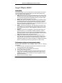
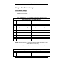
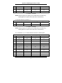
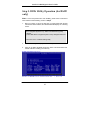
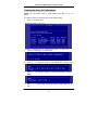
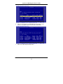
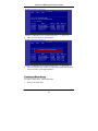
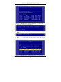
SiS 180 S-ATA User’s Manual
Quick User’s Guide
Version 0.1
Serial ATA RAID Quick User’s Guide
Edition
April 2003
Copyright
Trademarks
SiS is a registered trademark of Silicon Integrated Systems Corp.
All brand or product names mentioned are trademarks or registered
trademarks of their respective holders.
Revision History
Revision
0.1
History
First release
Date
May ‘03
Serial ATA RAID Quick User’s Guide
CONTENTS
Introduction ................................................................................................ 1
Step 0. What is RAID ................................................................................. 3
KNOW HOW.......................................................................................... 3
PERFORMANCE HINTS AND RECOMMEND SETTING............. 3
Step 1. Hardware Setup ............................................................................. 5
HARD DRIVES SETUP ........................................................................ 5
Step 2. Installing Software Drivers ........................................................... 8
WINDOWS 2000/XP .............................................................................. 8
NEW WINDOWS 2000/XP INSTALLATION................................................ 8
EXISTING WINDOWS 2000/XP INSTALLATION....................................... 9
CONFIRMING WINDOWS 2000/XP DRIVER INSTALLATION ................ 9
Step 3. BIOS Utility Operation (for RAID only) ................................... 10
CREATING AN ARRAY FOR PERFORMANCE........................... 11
CREATING A MIRROR ARRAY ..................................................... 13
CREATING A JBOD ARRAY............................................................ 16
CREATING A STRIPE-MIRROR ARRAY...................................... 18
Step 4. SIS 180 RAID Utility Operation ................................................. 21
VIEWING THE “CREATE RAID” ................................................... 23
CREATE A RAID SET........................................................................ 25
VIEWING THE RAIDTYPE MEANING.......................................... 31
DELETE A RAID SET ........................................................................ 33
RAID RECOVERY OPERATION ..................................................... 37
Serial ATA RAID Quick User’s Guide
Introduction
The 180 S-ATA controller is a hybrid solution that combines two independent
SATA ports and one Ultra ATA port for support of up to two Serial ATA
(Serial ATA RAID) and two Ultra ATA (Ultra ATA RAID) drives.
Specifications are as follows:
Serial ATA Interface
Serial ATA (SATA) is the latest generation of the ATA interface. SATA hard
drives deliver blistering transfer speeds of up to 150MB/sec. Serial ATA uses
long, thin cables, making it easier to connect your drive and improving the
airflow inside your PC.
♦ Supports 150 MB/s transfers with CRC error checking
♦ Large LBA support for drives over 137 GB
♦ Data handling optimizations including tagged command queuing, elevator seek
and packet chain command
Ultra ATA Interface
♦
♦
♦
♦
Standard ATA/IDE interface
Supports Ultra ATA/133, Ultra ATA/100, and Ultra ATA/66 drives
Supports CRC error checking for Ultra ATA drives
Separate timing control for two devices attached to one ATA channel
Serial/Ultra ATA RAID Interfaces
The Serial/Ultra ATA RAID is designed to provide a cost-effective, high
performance RAID solution that adds performance and/or reliability to PC
desktops and/or servers using Serial ATA/150, Ultra ATA/133, Ultra ATA/100,
Ultra ATA/66 hard disks.
Serial/Ultra ATA RAID function supports striping (RAID 0), mirroring (RAID
1), striping + mirroring (RAID 0+1) and span (JBOD). Please note that the
function supports hard disk drives only.
With striping, identical drives can read and write data in parallel to increase
performance. Mirroring increases read performance through load balancing
and elevator sorting while creating a complete backup of your files. Span
would increase the logic hard disk space.
Serial/Ultra ATA RAID striped arrays can double the sustained data transfer
rate of Serial ATA/150 and Ultra ATA/133 drives. Serial/Ultra ATA RAID fully
supports Serial ATA/150 and Ultra ATA/133 specification of up to 150MB/sec
per drive, depending on individual drive specifications.
1
Serial ATA RAID Quick User’s Guide
The technology also offers fault tolerant, data redundancy for entry-level
network file servers or simply for desktop PC users wanting to continually
protect valuable data on their PC. The Serial/Ultra ATA RAID offers RAID 1
mirroring (for two drives) to protect data. Should a drive that is part of a
mirrored array fail, Serial/Ultra ATA RAID technology uses the mirrored drive
(which contains identical data) to assume all data handling. When a new
replacement drive is later installed, Serial/Ultra ATA RAID rebuilds data to
the new drive from the mirrored drive to restore fault tolerance.
2
Serial ATA RAID Quick User’s Guide
Step 0. What is RAID
Know How
This section will give you an overview about the RAID system and introduce
the basic background and glossary which you need to know before using
“SiS 180 RAID Controller Application”.
1. RAID: (Redundant Array of Independent Disk Drives) use jointly several
hard drives to increase data transfer rates and data security. It depends
on the number of drives present and RAID function you select to fulfill
the security or performance purposes or both.
2. RAID 0: Also known as “Stripping”. All of the data are distributed evenly
to all of the existing drives. You gain benefits on performance because
the data transfer rate is multiplied by the number of drives. However,
RAID 0 has high risks of data security. All of the stored data will be lost if
even any one drive in the RAID set crashes.
3. RAID 1: Also known as “Mirroring”. Two hard drives are required. The
goal of RAID 0 is to ensure data security. Data is written to two or more
drives synchronously. That is, 100% duplication of data from one drive
to another.
4. RAID 0+1: Also known as “StripeMirror”. At least four hard drivers are
required. RAID 0+1 is a combination of RAID 0 and RAID 1. Data is
striped into two drives then mirrored. It provides high performance and
high data protection. This is a costly solution as RAID 1 because the two
mirrored drives represent an expensive insurance
5. JBOD: (Just a Bunch of Drives). Also known as “Spanning”. Two or
more hard drives are required. Several hard disk types configured as a
single hard disk. The hard drives are simply hooked up in series. This
expands the capacity of your drive and results in a useable total capacity.
However, JBOD will not increase any performance or data security.
Performance hints and recommend setting
For the best performance and reliability, please read the following
suggestions.
1. In serial ATA port, use Native serial ATA drives. Parallel ATA to Serial
ATA converter board is NOT suggested.
2. In parallel ATA port, use ATA 66/100/133 hard drives
3. Use the same model hard drives.
4. If you have only two serial ATA drives, the auto-configure function will
assign each on a different channel as a master drive. Using only two
parallel ATA drives to create a RAID array is NOT suggested. It might
decrease performance.
5. Always use 80-conductor cables.
3
Serial ATA RAID Quick User’s Guide
6. We strongly recommend you should use “DMA” transfer mode.
7. The recommended block size is 64K when creating RAID 0 and
RAID 0+1.
8. The best selecting sequence of creating RAID 0+1 is Primary
Master(1) -> Secondary Master(3) -> Primary Slave(2) ->
Secondary Slave(4).
4
Serial ATA RAID Quick User’s Guide
Step 1. Hardware Setup
Hard Drives setup
The 180 controller supports up to two Serial ATA hard drives and two
Parallel ATA hard drives.
Any combination to 2, 3 or 4 Hard disk would combine to a strip system.
HDD Population Rules for RAID 0 (Striping)
Ultra ATA (Master)
Ultra ATA (Slave)
Serial ATA (Master 1)
Serial ATA (Master 2)
1
V
V
X
X
2
V
X
V
X
3
V
X
X
V
4
X
V
V
X
5
X
V
X
V
6
X
X
V
V
V
V
X
V
7
V
8
V
V
X
9
V
X
V
V
10
X
V
V
V
11
V
V
V
V
V = Install; X = Uninstall
NOTE: Storage Capacity: the number of hard drives times the capacity of the
smallest drive in the disk array
Working Speed: the speed of the lowest drive in the disk array
Any of 2 Hard Disk would make a mirror system.
HDD Population Rules for RAID 1 (Mirroring)
Ultra ATA (Master)
Ultra ATA (Slave)
Serial ATA (Master 1)
Serial ATA (Master 2)
1
V
V
X
X
2
V
X
V
X
5
Serial ATA RAID Quick User’s Guide
3
V
X
X
V
4
X
V
V
X
5
X
V
X
V
6
X
X
V
V
V = Install; X = Uninstall
NOTE: Storage Capacity: the capacity of the smallest drive in the disk array
Working Speed: the speed of the lowest drive in the disk array
4 Hard disk would set up a RAID 0 + 1
HDD Population Rules for RAID 0+1 (Striping + Mirroring)
1
Ultra ATA (Master)
Ultra ATA (Slave)
Serial ATA (Master 1)
Serial ATA (Master 2)
V
V
V
V
V = Install; X = Uninstall
NOTE: Storage Capacity: the capacity of the smallest drive in the disk array
Working Speed: the speed of the lowest drive in the disk array
Any combination to 2, 3 or 4 Hard disk would combine to a JBOD system.
HDD Population Rules for JBOD (Spanning)
Ultra ATA (Master)
Ultra ATA (Slave)
Serial ATA (Master 1)
Serial ATA (Master 2)
1
V
V
X
X
2
V
X
V
X
3
V
X
X
V
4
X
V
V
X
5
X
V
X
V
6
X
X
V
V
7
V
V
V
X
8
V
V
X
V
9
V
X
V
V
10
X
V
V
V
11
V
V
V
V
6
Serial ATA RAID Quick User’s Guide
V = Install; X = Uninstall
NOTE: Storage Capacity: the number of hard drives times the capacity of the
smallest drive in the disk array
Working Speed: the speed of the lowest drive in the disk array
7
Serial ATA RAID Quick User’s Guide
Step 2. Installing Software Drivers
SiS provides Mini IDE driver for SiS180 SATA function and RAID driver for
SiS180 SATA with RAID function.
SiS Mini IDE driver for Windows 2000/XP
SiS RAID driver for Windows 2000/XP
1.
2.
For SATA function, both of Mini IDE driver and RAID driver support
SATA.
For RAID function, SiS180 support RAID0, RAID, RAID0+1 and JBOD
by software RAID driver only.
For special occasions, users can refer to the following section with
details on the SiS180 driver installation when used with various
operating systems.
Windows 2000/XP
New Windows 2000/XP Installation
The following details the installation of the drivers while installing
Windows 2000/XP.
1. Start the installation:
Boot from the CD-ROM. Press F6 when the message “Press F6 key
if you need to install third party SCSI or RAID driver” appears.
2. When the Windows 2000/XP Setup window is generated, press S
key to specify an Additional Device(s).
3. Insert the driver diskette into drive A: and press Enter.
4. Choose one of the following items:
“WinXP SiS Raid/IDE Controller “ (for RAID),
“WinXP SiS Mini IDE Controller” (for SATA),
“Win2000 SiS Raid/IDE Controller” (for RAID),
“Win2000 SiS Mini IDE Controller” (for SATA) that appears on
screen, and then press the Enter key.
8
Serial ATA RAID Quick User’s Guide
5. Press Enter to continue with installation or if you need to specify
any additional devices to be installed, do so at this time. Once all
devices are specified, Press Enter to continue with installation.
6. From the Windows 2000/XP Setup screen, press the Enter key.
Setup will now load all device files and then continue the Windows
2000/XP installation.
7. Please install the driver package again (ex. SiS RAID driver v1.00)
while the operation system has been setup.
Remark:
If you would like to install windows to any RAID set, you should
create RAID from BIOS utility first and then follow the steps above.
Existing Windows 2000/XP Installation
1.
Install the driver by execute SiS driver setup utility.
2.
The drivers and WinXP RAID utility will be automatically installed.
Confirming Windows 2000/XP Driver Installation
1.
From Windows 2000/XP, open the Control Panel from “My
Computer” followed by the System icon.
2.
Choose the “Hardware” tab, then click the “Device Manager” tab.
3.
Click the “+” in front of “SCSI and RAID Controllers” hardware type.
The driver “WinXP SiS180 Raid Controller” (for RAID) or
“Win2000/XP SiS180 IDE Controller” (for SATA) should appear.
9
Serial ATA RAID Quick User’s Guide
Step 3. BIOS Utility Operation (for RAID
only)
Note: For the best performance and reliability, please read “Performance
Hints and Recommend Setting” section in Step 0
1.
Boot your system. If this is the first time you have booted with the SIS
180 and the drives installed, the onboard BIOS will display the following
screen.
Silicon Integrated Systems Corp. RAID Card BIOS Setting Utility
1.00.0.XX
(c) 2003-2006 Silicon Integrated Systems Corp. All Rights Reserved.
Press <Ctrl><S> to run BIOS Setting Utility
2.
Press <Ctrl-S> keys to display the SIS180 Utility Main Menu.
3.
Press “R” to display the RAID setup menu below. This is the fastest and
easiest method to creating your first array.
10
Serial ATA RAID Quick User’s Guide
Creating an Array for Performance
NOTE: SIS 180 enables users to create striped arrays with 1, 2, 3, or 4
drives.
To create an array for best performance, follow these steps:
1.
Press “A” to create array .
2.
Press <2> and <Enter> to select Stripe .
3.
Press <1>─<7> keys and <Enter> to select Block Size. ( Default : 32K )
4.
Press <1>─<2> keys and <Enter> to select Transfer Mode. ( Default :
DMA )
5.
Use<↑> <↓> to select disk , and press <Enter> to select disk, <Q> to
exit.
11
Serial ATA RAID Quick User’s Guide
6.
Press <N> and <Enter> to Create Stripe only. (If Press <Y> and
<Enter>, it will split the data on source disk to other disks)
7.
Press <Q> until escape the setup menu
12
Serial ATA RAID Quick User’s Guide
8.
Press <Y> and <Enter> to save changes.
9.
Once the array has been created, you will need to FDISK and format the
array as if it were a new single hard drive.
Creating a Mirror Array
To create an Mirror array , follow these steps:
1.
Press “A” to create array .
13
Serial ATA RAID Quick User’s Guide
2.
Press <3> and <Enter> to select Mirror.
3.
Press <1>─<2> keys and <Enter> to select Transfer Mode. ( Default :
DMA )
4.
Use<↑> <↓> to select disk , and press <Enter> to select disk, <Q> to
exit.
14
Serial ATA RAID Quick User’s Guide
5.
Press <N> and <Enter> to Create Mirror only. (If Press <Y> and
<Enter>, it will Duplicate the data on source disk to mirror disk)
6.
Press <Q> until escape the setup menu
7.
Press <Y> and <Enter> to save changes.
15
Serial ATA RAID Quick User’s Guide
8.
Once the array has been created, you will need to FDISK and format the
array as if it were a new single hard drive.
Creating a JBOD Array
To create an JBOD array , follow these steps:
1.
Press “A” to create array .
2.
Press <1> and <Enter> to select JBOD.
16
Serial ATA RAID Quick User’s Guide
3.
Press <1>─<2> keys and <Enter> to select Transfer Mode. ( Default :
DMA )
4.
Use<↑> <↓> to select disk , and press <Enter> to select disk, <Q> to
exit.
5.
Press <Q> until escape the setup menu
6.
Press <Y> and <Enter> to save changes.
17
Serial ATA RAID Quick User’s Guide
7.
Once the array has been created, you will need to FDISK and format the
array as if it were a new single hard drive.
Creating a Stripe-Mirror Array
To create an Stripe-Mirror array, follow these steps:
1.
Press “A” to create array.
2.
Press <4> and <Enter> to select Strpie-Mirror.
18
Serial ATA RAID Quick User’s Guide
3.
Press <1>─<7> keys and <Enter> to select Block Size. ( Default : 32K )
4.
Press <1>─<2> keys and <Enter> to select Transfer Mode. ( Default :
DMA )
5.
Use<↑> <↓> to select disk , and press <Enter> to select disk, <Q> to
exit.
6.
Press <Q> until escape the setup menu
19
Serial ATA RAID Quick User’s Guide
7.
Press <Y> and <Enter> to save changes.
8.
Once the array has been created, you will need to FDISK and
format the array as if it were a new single hard drive.
20
Serial ATA RAID Quick User’s Guide
Step 4. SIS 180 RAID Utility Operation
Note: For the best performance and reliability, please read “Performance
Hints and Recommend Setting” section in Step 0.
1) After installing the SiS RAID utility, go to “Start” menu and choose
“Programs.” From the “Programs” menu, choose “SiS RAID Utility” and
click on “SiSRaid”
2) The SiS RAID Utility window opens as below. The main interface has two
tabs: View and Configuration. You can switch to different tabs by clicking
on it. On “View” tab, we can see some device information. The default
value is the information of the first device.
21
Serial ATA RAID Quick User’s Guide
3) Click the tab “configuration”, you can find three tabs: Create Raid, Delete
Raid and Raid Recovery. In the same way, you can switch to different
tabs by clicking on it.
22
Serial ATA RAID Quick User’s Guide
4) Click the tab “Create Raid”, you can find three drop-down box and three
panes. Those meaning will be showing below.
Viewing the “Create Raid”
a)
Raid Type: Click the drop-down box “Raid Type”. This box enables the
user to select array type. There are four array types that the user can
select: JBOD, RAID 0, RAID 1 and RAID 0+1. User can select any one
array type to create a RAID set.
b)
Block Size: If user selected RAID 0 and RAID 0+1 array types in the
“Array Type” box, the “Block Size” drop-down box will be enabled and
user must select a block size. Clicking the drop-down box “Block Size”,
there are seven block size that the user can select: 8k, 16k, 32k, 64k,
128k, 256k and 512k. User can select any one block size to create a
RAID 0 or RAID 0+1 set. The default selection is 64k.
23
Serial ATA RAID Quick User’s Guide
c)
Mode Type: Click the drop-down box “Mode Type”. This box enables
the user to select mode type. There are two mode types that the user
can select: PIO and DMA. User can select any one mode type to
create a RAID set. The default selection is DMA.
d)
Available Disks: This pane will list out all the disks that can be used to
create a RAID set currently. It will show some disk information (ex.
Location, serial numbers, the ability of boot and the status of
recovering).
24
Serial ATA RAID Quick User’s Guide
e)
Selected Disks: This pane will list out all the disks that have been
selected to create a RAID set. User can highlight the specific disk that
we wants in the “Available Disks” pane and click the downward arrow
icon or double click the marked disk to select that disk into the
“Selected Disks” pane. In the same way, user can click the upward
arrow icon or double click the marked disk in the “Selected Disks” to
get back the disk that we might select wrong to the “Available Disks”
pane.
f)
Information: This pane will show the information about creating a RAID
set after clicking the button “Create”. The information may be “Please
select the <Raid Type> first!”, "Please select the <Mode Type> first!",
"Please select the <Block Size> first!", "Please select the disk you want
first!", "Mirror supports TWO DISKS only.", "StripeMirror needs least
FOUR DISKS.", "Raid Created successful! Reboot please!!" or "Raid
Creation failed!".
Create a RAID set
a) To create a JBOD array, follow these steps:
1. “Configuration” → “Create Raid” → “Raid Type” → JBOD.
2. From the drop-down box “Mode Type”, select the mode type you want.
3. From the “Available Disks” pane, select the disk and click downward
arrow icon or double click it to add the disk on the “Selected Disks”
pane.
25
Serial ATA RAID Quick User’s Guide
NOTE: You must have at least two hard disks to create a JBOD array.
4. When the JBOD array’s configuration is finished, click the button
“Create”. Then a warning message will be popup. Pay attention to the
warning message, and then click “Yes” button to finish the creation of
JBOD array, or click “No” button to cancel.
NOTE: If the disk you selected has the ability of booting, another
warning message will be popup before “SiS Software RAID”
message. You can click “Yes” button to continue or click “No”
button to cancel.
26
Serial ATA RAID Quick User’s Guide
5. Next, another message box will be popup to tell user that disk setting
has been changed and ask whether to restart the computer or not.
Click “Yes” button to restart the computer or click “Cancel” button to
skip restarting.
NOTE: New Setting will take effect after restarting only.
b) To create a RAID 0 (Stripe) array, follow these steps:
1. “Configuration” → “Create Raid” → “Raid Type” → RAID 0.
2. From the drop-down box “Block Size”, select the block size you want.
3. From the drop-down box “Mode Type”, select the mode type you want.
4. From the “Available Disks” pane, select the disk and click downward
arrow icon or double click it to add the disk on the “Selected Disks”
pane.
27
Serial ATA RAID Quick User’s Guide
NOTE: You must have at least two hard disks to create a RAID0 array.
5. When the RAID0 array’s configuration is finished, click the button
“Create”. Then a “Create Stripe RaidSet” dialog will be popup.
<Note>
Source: The first selected disk.
Target: All other disks but first one.
Create Only: This operation will destroy all data on all the selected
disks and create a clean stripe array without any data
on it.
Split data (Boot from IDE): Split operation will split data from source
disk into all the selected disks. In this
operation, the boot disk can’t be placed on
180.
Split data (Boot from 180): This operation is similar to “Split data into
Raid0” operation, but system boots from
180.
Ok: Start the operation.
Cancel: Cancel the operation.
<Disk Copy Remaining Sector>: Show the remaining splitting data.
NOTE: miniCapacity x N > SourceCapacity
miniCapacity: The minimum size of all selected disks.
SourceCapacity: The size of source disk.
N: Total disk numbers.
28
Serial ATA RAID Quick User’s Guide
6. Next, you can click “Cancel” button to leave or click “Ok” button to
continue after the operation being selected. The differential warning
messages will be popup following the differential operations. The
warning messages are similar to JBOD array creation but the
operation is “Split data into Raid0”.
7. If the operation is “Split data into Raid0”, a warning message will be
popup, seeing below:
Next, you can click “Yes” button to start the operation or click “No”
button to cancel.
8. When the operation is finished, the restart warning message will be
popup as well as JBOD array creation except for the operation “Split
boot OS into Raid0”.
Next, you can click “Ok” button to restart the windows and start the
operation “Split boot OS into Raid0”. Or click “Cancel” button to
suspend this operation. But, this operation is still done after restarting
the windows next time.
c) To create a RAID 1 (Mirror) array, follow these steps:
1. “Configuration” → “Create Raid” → “Raid Type” → RAID 1.
2. From the drop-down box “Mode Type”, select the mode type you want.
3. From the “Available Disks” pane, select the disk and click downward
arrow icon or double click it to add the disk on the “Selected Disks”
pane.
29
Serial ATA RAID Quick User’s Guide
NOTE: The RAID1 array supports two hard disks only.
4. When the RAID1 array’s configuration is finished, click the button
“Create”. Then a “Create Mirror RaidSet” dialog will be popup.
<Note>
Source: The first selected disk.
Target: The second selected disk.
Create Only: This operation will destroy all data on all the selected
disks and create a clean mirror array without any data
on it.
Create and Duplicate: Duplicate operation will reserve data on the
source disk and copy them onto the target disk.
Ok: Start the operation.
Cancel: Cancel the operation.
<Disk Copy Remaining Sector>: Show the remaining copying data.
30
Serial ATA RAID Quick User’s Guide
5. Next, you can click “Cancel” button to leave or click “Ok” button to
continue after the operation being selected. The warning messages
will be popup following the differential operations and the message is
similar to JBOD array creation.
6. When the operation is finished, the restart warning message will be
popup as well as JBOD array creation.
d) To create a RAID 0+1 (StripeMirror) array, follow these steps:
1. “Configuration” → “Create Raid” → “Raid Type” → RAID 0+1.
2. From the drop-down box “Block Size”, select the block size you want.
3. From the drop-down box “Mode Type”, select the mode type you want.
4. From the “Available Disks” pane, select the disk and click downward
arrow icon or double click it to add the disk on the “Selected Disks”
pane. Please see the “Performance hints and recommend setting”
section for best settings.
5. When the RAID0+1 array’s configuration is finished, click the button
“Create”. Then a warning message will be popup. The message is
similar to JBOD array creation.
6. Next, the restart message will be popup.
NOTE: The RAID0+1 array support at least four hard disks.
5) Click the tab “Delete Raid”, you can find some panes and two
buttons. The RaidType meaning will show below.
Viewing the RaidType meaning
General case: RAID0 (A = B C | D E)
<Meaning>
RAID0: Raid Type
A: total number of disks in this Raid
B,C: the serial number of each disk in this Raid
D,E: a) Raid is correct, B=D C=E
b) Raid is error, D or E will show “?” or “!”.
In which, the meaning of “?” and “!” will show below.
31
Serial ATA RAID Quick User’s Guide
<Example>
<Showing its information>
32
Serial ATA RAID Quick User’s Guide
Delete a Raid set
a) To delete a JBOD, RAID0 or RAID1 array, follow these steps:
1. “Configuration” → “Delete Raid”, the following windows will appear:
33
Serial ATA RAID Quick User’s Guide
2. Highlight the disk array in the “Current RaidType” pane, and then click
the “Information” button or double click the array. You can get some
information about the disk array.
3. If you want to delete a disk array you selected, you can highlight the
disk array and then click the button “Delete”. Then a warning message
will be popup, and pay attention to the warning message. You can click
“Yes” to delete the selected disk array or click “No” to cancel.
34
Serial ATA RAID Quick User’s Guide
4. Next, another message will be popup to tell user the setting of these
disks have been changed and ask whether to restart the computer.
b) To delete a RAID0+1 array, , follow these steps:
1. “Configuration” → “Delete Raid”, highlight the disk array in the “Current
RaidType” pane, and then click the “Information” button or double click
the array. You can get some information about the disk array. The
following windows will appear:
2. If you want to delete a disk array you selected, you can highlight the
disk array and then click the button “Delete”. Then a warning message
will be popup, and pay attention to the warning message.
35
Serial ATA RAID Quick User’s Guide
3. Next, you can click the button “Delete” to delete this RAID0+1 array and
all disk will become single disk. Then some warning messages which
are the same with previous those will be popup.
4. Or, you can click the button “Degrade” to degrade RAID0+1 set to
become a completed RAID0 set. See below:
NOTE: The degrading operation is workable only when the RAID 0+1
set has any one completed RAID 0 set existed.
6) Click the tab “Raid Recovery”, you can find two panes and some buttons.
Those meaning will be showing below.
36
Serial ATA RAID Quick User’s Guide
Raid Recovery Operation
NOTE: The recovering operation is workable only when error RAID1 set
or error RAID0+1 set (must at least an error RAID0 set) exist.
a) First, you can click the button “Available Raid” to find whether any error
Raid set existing. See below:
Next, highlight the error Raid set you want to recovery. And you can click
the button “Ok” to continue or click “Cancel” to cancel this operation.
b) After “Available RAID” selected, click the button “Available Disk” to find
whether any empty hard disk existing. See below:
37
Serial ATA RAID Quick User’s Guide
Next, highlight the empty hard disk you want to select. And you can click
the button “Ok” to continue or click “Cancel” to give up this selection.
c) When the “Available Raid” and “Available Disk” is finished, you can click
the button “Start” to start this operation. And the button “Start” will
become “Pause”. Then you can click the button “Pause” to pause the
thread operation. And the button “Pause” will become “Start”. Or you can
click the button “Stop” to cancel this operation.
38