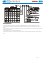
1
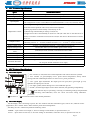
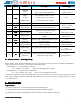
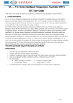
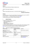
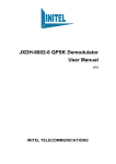
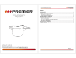
YL — 7 □ Series Intelligent Temperature Controller (ITC)
ITC User Guide
★ Please read carefully this entire User Guide before operating ITC. Keep this guide for future references。
1. Product Descriptions
The YL-7 Series is designed and manufactured strictly based on European CE standards, and has gone through five rigorous
tests including testing in extreme temperatures (-20℃ to 75℃), testing in various work loads and conditions, and testing
using specialized instruments. These tests are designed to ensure the ITC is accurate, reliable and durable in various
applications under normal and special working conditions.
YL-7 Series employs advanced expert fuzzy technology and Dual Control Logics. Its built-in auto-calibration intelligence
ensures that ITC’s performance is accurate, reliable and durable, and can track, lock, revise and react quickly to temperature
changes. The built-in auto-calibration intelligence is particularly useful for special temperature control applications, e.g.,
operating multiple equipments with different temperature requirements each and the resulted heat interference, or, having
specific requirements on temperature control related to factors such as heating and cooling capacity and ambiance
temperatures. In these special applications, users can easily and quickly obtain a custom set of P, I, D values for their special
applications, As a result, YL-7 Series ITC can be used in a wide range of applications. YL-7 Series is an excellent controller
for machineries in food processing, glass-making, plastic forming, publishing, packaging, and metal processing. YL-7
Series is also the preferred temperature controller for processes such as temperature sensitive drying, metal heat-treatment,
and chemical and mechanic treatments.
e.
This series of products has got the European CE certificat
certificate.
Product Features:
•
•
•
•
•
Easy one-touch auto-calibration for optimal performance
Fast auto-calibration with high accuracy and reliability
Capable of accepting any range of values and settings from thermal couples and resistors, and from modeling
Base zero is adjustable and fully controlled by software, with the precision of ±0.2%FS.
The main outputs:
"R" – Relay controlling AC contactor
"S" – Impulse zero triggering SSR
"I" – Current output 4-20mA
"U" – Voltage output 0 – 5 VDC
•
Two independent alarm channels, which can be programmed to set 4 kinds of alarm combinations.
Page 1
2. ITC Technical Specifications
Specs
Setting Accuracy
Measuring Accuracy
Sampling Frequency
Input Signals
Temperature Control
Output Control
Relay Contact Load
Impulse Voltage Load
Model Current Voltage
Load
Alarming
Alarm Output
Power Consumption
Insulation Resistant
Technical Parameter
All ranges ±0.5% FS, within one degree
±0.2% FS, within one degree
2 / Second
Standard inputs,
all configurations :E,K,N,J,T,S,R,B,Wer,Cu50,Pt100,Pt100/0.1,0-5V,1-5V,0-10mA,4-20mA
(1) Intelligent setting:factory Initial setting P,I,D.But when the temperature is fluctuating
around the critical point,the value of P,I and D can be adjusted.
(2)Time proportional control:modify I=0,D=0,keep P =20.
(3)Reach-stop control:modify P=0,keep I=150,D=30;
(4)Upper-lower limit control:modify P=0,and set "HY"(the 16th item in the third level of
menu) as needed to control the section,and set "Ft"(the 21th item in the third level of menu)
set as "0".
Switch Control:"R" – Relay Contact, "S" – SSR zero triggering.
Modeling Control: "I" – 0-10mA,4-20mA continuous; "U" – 0-5VDC, 1-5VDC continuous.
250VAC / 3A (Resistance),250VAC / 1A (Conductive,Cosф=0.4)
12VDC,Max 40mA (To drive SSR,to protect short circuit)
(Standard) 0-5VDC,4-20mA,Load Resistance Max=500Ω
Set upper and lower Limit on Deviation and absolute level
Relay:250VAC / 3A(Resistor), 250VAC / 1A(Sensing,Cosф=0.4)
80-260VAC, 50-60Hz, ≤3W
≥10MΩ(Testing Condition 500VDC)(Outputting current or non-contactor voltage; no test
for I/O ports and the resistance of CT input)
Ambiance Temperature
Temperature:-20~+75°c Humidity:35 ~85%RH
3. ITC Technical Specifications
1) ITC Panel Layout
⑧
Decrease or ⑨
① "PV" window (in red):shows the actual temperature and various functions symbols
② "SV" window (in green):displays user’s preset desired temperature, factory initial
settings,and auto-calibrated parameters as well as user’s preset parameters.
③ "ON" (green light on)indicates the output ports are open;"ON" (green light go out)
indicates the output port is closed.
④ "AT" light (yellow) flashes during ITC’s auto-calibration process.
⑤ "ALM1","ALM2":Signal lights of two alarm channels (red),operating independently.
⑥ "MD":Mode selection key for: presetting, reviewing or confirming settings and parameters.
⑦
Activating auto-calibration; move the cursor left when setting calibration
parameters.
increase the values to the desired parameters.
2) ITC Panel Display
①Normal display: After connecting to power, the "PV" window will show transmitter types, such as "K", and then current
temperature; "SV" window shows "PID" and then preset desired temperature.
②Normally, the "PV" window may flash the following values
"HHHH" – input values are too high, or, incorrect settings on transmitter, or input disconnect; etc.
"LLLL" – input values are too low, or, incorrect settings on transmitter, connection error; or input short circuit; etc
Page 2
"Erro"– Exchange parameter out of ranges, incorrect settings on transmitter, connection errors, short circuit in input
source, or disconnect,etc.
Values displayed in the “PV” window are correct despite the "HHHH"and "LLLL" errors but the "PV" values are incorrect
under the error message"Erro".
3) ITC Functions and Parameters
Setting of the temperature:After instrument start to work, click "MD" key lightly, then the first green LED flashes on the
right side below "SV" window, enter the state of setting temperature, each click "
" key, cursor shift leftwards as the
digital tube flashing at the same time, until temperature become a desired value, with pressing " " or " " key to chang
temperature value to be what is needed.At last,press "MD" to confirm the setting and exit the menu.
For setting, modifying the upper limit and lower alarm threshold value, and adjusting the P, I, D and other parameters, users
should enter the second level menu to set and modify them. Specific operation is as follow:Press "MD" key for about 6
seconds, "AL1" ( the upper limit alarm ) will appear on "PV" window, and "50" appears on "SV" window, then each click on
the "MD" key, press the sequence parameters, reset or modify any function parameters,as user need.
Please refer to the table below password and operate in order:
Symbol
Term
Ranges
Descriptions
Initial
AL1
Alarm Upper
limit
-199~9999
℃
Set alarm upper limit,and deviation of this limit over preset
temperature value
50℃
AL2
Alarm Lower
Limit
-199~9999
℃
Set alarm lower limit,and deviation of this limit under preset
temperature value.
0℃
Pb
Measurement
Revision
-99~+100℃
Revise deviations from initial circuit input and from
compensating thermal couple (resistor)
0℃
P
Scaling setting
(Heating)
0.0~999.9℃
Set interval control, P=20℃ in general or 50℃ for
powerful heater Set P=0 for point control.
20℃
I
Integral Time
(Repetitive)
0~ 3600s
Mostly 60~240S. Increase I if temperature fluctuates
regularly; decrease I for persistent deviations.
150s
AT
Differential Time
(Preset)
Control Cycle
(Heating)
Auto-Calibration
Lock
User Input Lock
D
T
0~1
Mostly 1/3~1/5. Increasing D lessens system’s over-heat but
weaken the anti-interference capability
Set temperature control cycles. Cannot set to"0".Relay
output: 20 seconds; Logic
"0"= Off;"1"=On (See Control Panel)
20s/2s
/1s
0
0~2
"0":free to input;"1":input preset only;"2":locked
0
0.0~999.9s
1~99 s
30s
4) Advanced Parameter Settings
This intelligent series has advanced settings (Third level special parameters menu) for engineers or senior experienced users.
Ordinary users had better not regulate the original parameters, in order to avoid confusing procedures.
Method of operation to enter third level menu is as follow:Press and hold both the"MD" and
keys at the same time
until "PASS" is shown in the SV window and "0000" is shown in the PV window.Then, release
key after release
"MD" key. Input "01000" in the SV window to enter the "menu code" as follow,thus you can reset or modify relevant
parameters.Press "MD" key to confirm after set or modify parameters in order,then return to "PASS" and exit the menu.
Please refer to the table below password and operate in order:
Page 3
Codes
Symbol
Definition
Descriptions
Values/Ranges
12
Sn
Transmitter
Models
"Pt1"= Pt100 (-2~650℃);"Pt0.1"= Pt100
(–199.9~+199.9℃). Make changes over
lines. Factory setting = Model "K".
E,K,N,J,T,S,R,B,Wer,Cu
50,Pt1,Pt0.1,0-5V,1-5V,0
-10mA,4-20mA
Alarms
Settings
"0": Upper/Lower limits =(A)/(A)
"1":Upper/Lower limits = (D)/(A)
(A:Absolute value
D:Offset value )
"2":Upper/Lower limits =(A)/(D)
"3":Upper/Lower limits =(D)/(D)
Factory Initial setting:1
0,1,2,3
13
ALP
14
SETL
Minimum Preset
Preset minimum value based on transmitters
15
SETH
Maximum Preset
Preset max value based on transmitters
Factory
Initial:K~0℃/1300℃
16
HY
Control Points
Interval control values or alarm ranges
0~50.Initial:0
17
PSL
Input Zero Value
18
PSH
Input Full Value
19
DP
Decimal Points
For Linear signals. Not for Thermal couples or
resistors
0~3.Factory
Initial setting:1
20
Ctrl
Potential
Temperature
Specially, set the temperature between ±Tt and
proceed it steadily.
0~20
Factory Initial:15
21
Ft
Primary Output
Power In Charge
Prevent the temperature up and down after in
charge repeatedly
0~100
Factory Initial:10%
22
Ov
Primary Output
Power Of Scaling
Setting
Set a primary output power when temperature
come into scaling setting firstly,
23
Tt
Suspend Exceed
Maximum
When temperature exceed the preset one
(temperature keep growing)
Applicable when input linear signals
(current or voltage, etc)
-1999~9999
Factory Initial:0 / 500
0~100
Factory Initial:10%
0~10
Factory Initial:1℃
5) Advanced Functions – Linear Signal Input
When inputting Leaner signals,both"PSH"and "DP" have to be defined correctly for this ITC to maximize its performance.
Leaner signal values can be 0-5V,1-5V,or 0-10mA,4-20mA.Especially:
①If input signal is 0-5V,the PV value is defined by
PV = Vx/(PSH – PSL)+ PSL
where Vx is the input signal, in Voltage
②If input signal is 1-5V,the PV value is calculated by
PV =(Vx –1)/(PSH – PSL)+ PSL
where Vx is the input signal, in Voltage
③When input signals are 0-10mA and 4-20mA, they can be converted into 0-5V and 1-5V voltage signals using resistors
with 250Ω and 500Ω, respectively. Their"PSH" and "DP" values can then be calculated accordingly using the 0-5V and
1-5V formulas above.
4. Wire Connection Map
1.Special Notes
(1) Thermal couples input, use compensating wire with corresponding codes
(2) Thermal resistor input, use three identical compensating wires with low resistant
(3) Signal input wires should avoid magnetic interference from power lines electronic applicants.
2.Wire Connection Layout
Page 4
(1) YL-7A
(2) YL –7B
(3) YL–7D
(4) YL–7E
Notes
Notes::
•
Standard input signals 4~20mA can be converted into 0~5V using resistors 250Ω/500Ω, respectively.
•
Input connecting ports:use Ports (2) and (3);
5. ITC Series Number Descriptions
Please verify the products you received with your orders (series number, model, specs), as follows.
ITC product series number has 10 digits such as YL–07AR/12. Each digit shows the following information:
Digit
1st, 2nd
3rd
4th, 5th
6th
7th
8th
9th
10th
Possible Values Descriptions
YL
ITC Model
Separator
07
ITC Series
A to F
Product dimension and specs
See the table below for its W (wide), H (height), L (length), M, N, a, b for each values of A to F
R, S, I, U
R=Relay output 250V/3A; S=Impulse voltage output for SSR 12VCD/40mA
I=Current output 4-20mA, 0-10mA; U=Voltage output 0-5VDC, 1-5VDC
/
Separator
1,2,3
Input signals:
1=Thermal Couples: K, J, E, S, N, T, B, R, Wer
2=Thermal Resistor: Cu50, PT100
3=Linear signals: 0-10mA, 4-20mA, 0-5V, 1-5V
1,2
Secondary Controls
1=A1: One channel alarm control
2=A1, A2: two independent alarm channels,
any configuration combinations
Page 5
▲ ITC Operation Notes
1.Ambiance requirements for this ITC: pressure:86~105KPa,temperature 0~50℃,Relative humidity 45~ 85%RH.
2.Do not operate ITCs right after dramatic ambiance temperature changes such as moving from cold outdoor to warm
indoor.
3.Do not operate ITC in humid, salty and dusty surroundings or near combustible and corrosive materials such as gasoline,
chemicals, metal powders.
4.Do not operate ITC on a tremble and unstable structure.
5.When placing multiple ITCs in the same location, keep a distance of 25mm horizontally and 30mm vertically between
ITCs.
Page 6