1
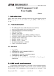
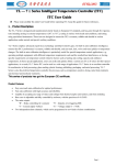
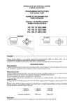
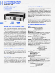
DTS-12C
Standalone Scrambler
User Manual
DTS-12A User Manual
Chapter 1 Product Outline
1.1 Outline
DTS-12A stand alone scrambler is applied in the simultcrypt scrambling of input code
stream. It can send fixed or agile word scrambling according to transport stream. The
built-in simulcrypt synchronization controller transmits the exchange information with
ECMG. When integrated with CA, the scrambler adjusts crypto period appropriately in order
to make decoder function normally. This is a highly integrated equipment for digital TV
scramble.
1.2 Features:
DVB common scramble system description ETR289,common scramble system description;
DVB Scramble designated program or transport stream;
Comply with DVB standard arithmetic ,supports simultcrypt, compatible with
multi- CA system;
Comprehensive MPEG code stream analysis;
Re-process PSI/SI information from TS;
Channel protection for ASI output;
Bit rate auto adaption, PCR reset and re-mark;
Remote real-time monitor of transport stream;
Auto switch and input backup
pocket format : auto adaption of 188/204 bit rate
Network monitor
PCR correction
1.3 Application
Program collect/ distribute
Page 1
DTS-12A User Manual
SDH network transport , satellite DVB-T, MMDS
Digital CATV Front head end
Video on demand (VOD)
Digital swerve
Video distribution for television network
Program encrypt
Transport stream disposal
Satellite
Encoder
Scrambler
Modulator
Encoder
Scrambler
Modulator
Encoder
Scrambler
Modulator
Scrambler
Modulator
receiver
Multip
lexer
Satellite
receiver
Mixer
Satellite
receiver
Multip
lexer
Satellite
receiver
Encoder
Switch
Page 2
CA.SMS
Original front head
software
end of Center
DTS-12A User Manual
1.3 Technical Parameter
Import interface
DVB/ASI
1 route
Output Interface
DVB/ASI
2 routes
Output bit rate
1~54Mbps contunious&adjustable
Network port
Miscellaneous
Ethernet
10/100M
Dimension
44mm 482mm 410mm
Temperature
Power supply
0~45
Operating
-20~80
storage
220VAC±10%
50Hz 25W
1.4 Principle Frame
1.5 Appearance and description
Front panel illustration:
StandAlone Scrambler
Power
Enter Menu Lock
Lock
1
2
4
3
6
Page 3
75
8
9
10
11
Digital
Video
Broadcasting
DTS-12A User Manual
1
LCD Screen display
2
Power indicator (green)
3
Signal lock indicator
4
ECMG1 signal indicator
5
EMMG1 signal indicator
6
EMMG2 signal indicator
7
ECMG2 signal indicator
8
Up/down/left/right button
9
Confirm button
10
Cancel button
11
Menu button/lock button
Back panel illustration:
1
ASI TS output interface 1
2
ASI TS output interface 2
3
ASI TS input interface 1
4
ASI TS input interface 2
5
Ethernet interface
6
Power on-off
7
Fuse
8
Power socket
9
Grounding
Page 4
DTS-12A User Manual
Charter 2
Installation Guide
2.1 Acquisition check
Open the device package and check the articles, do check the packing material of samll
parts,check packed goods according to packing list or below items:
DTS-12C Stand Alone Scrambler
1 unit
User manual
1copy
Coaxial line with Q9 head for each ends
1 radix
AC input power cord
1 radix
If there is any missing or mismatch of above items, please contact local dealer.
2.2 Installation preparation
Follow below steps when installing the device.The detailed installation will be
described at the rest part of this chapter,the back panel illustration is for concrete positation
reference. Following content is the main for this chapter:
Checking if there any possible missing or damage device during transport.
Checking if the situation is suitable for installing.
Install Stand Alone Scrambler.
Connecting signal wires
Connecting communication port (for option)
2.2.1 Installation flow per below chart:
Acquisition
Check
Fixing
Device
Connecting
Grouding
Wire and
Power
Cord
Connecting
Signal Wire
Page 5
Setting
Parameter
Running
Device
DTS-12A User Manual
2.2.2 Environment Requirement
Item
Requirement
When user install machines array in one machine hall, the
Machine hall
distance between 2 row of machine frames should be 1.2~1.5m
space
and the distance to wall should be no less than 0.8m
Electric Isolation, Dust Free,
Machine hall
Volume resistivity of ground anti-static material : 1x10⁷~1x10¹⁰
floor
Grounding current limiting resistance : 1 M ,
Floor bearing should be greater than:
450Kg/m2.
Environment
Under 5~40 C operate for long time, under 0~45 C operate for short
temperature
time installing air-conditioning is recommended.
Relative
Under 20%~80% operate for long time under10%~90% operate for short
temperature
time.
Pressure
86~105KPa
Installing rubber strip for sealing door-gaps and dual level glasses for
Door & window
window.
be covered with wallpaper, or brightness less paint, rather than easy
Wall
pulverization dope.
Fire protection
Have Fire alarm system and extinguisher .
Requiring device power, air-conditioning power and lighting power are
Power
independent to each other. Device power requires AC power 220V 50Hz,
50W Please carefully check before running.
2.2.3 Grounding requirement
All function modules’ good grounding designs are the base of reliability and stability of
device. Also, they are the most important guarantee of lightning arresting and
interference rejection. Therefore, system must follow this rule.
Coaxial cable’s outer conductor and isolation layer should keep sound electric
conducting with the metal housing of device.
Page 6
DTS-12A User Manual
Grounding conductor must adopt copper conductor in order to reduce high frequency
impedance, and the grounding wire must be as thick and short as possible.
The 2 terminals of grounding wire must make sure for well electric conducting, and
process for antirust.
It is prohibited that users use other devices as part of grounding wire’s electric circuit
The section of the conjunction between grounding wire and device’s frame should be
equal or greater than 25 mm2
2.2.4 Frame Grounding
All the machine frames should connect to protective copper strip. The grounding wire
should be as short as possible and avoid circling. The section of the conjunction between
grounding wire and grounding strip should be equal or greater than 25mm2.
2.2.5 Device Grounding
Connecting the device’s grounding rod to frame’s grounding strip with copper
wire.
2.3 Wire’s Connection
The power supply outlet is located at the left of rear panel, and the power switch
is just above it. The protective grounding wire connective screw is located at the
down-left side of power supply outlet
Connecting Power Cord
User can insert one end into power supply outlet, while insert the other end
to AC power.
Connecting Grounding Wire
When the device solely connects to protective ground, it should adopt
independent way, say, share the same ground with other devices. When the device
adopts united way, the grounding resistance should be smaller than 1
Caution:
Before connecting power cord to Encoder, user should set the power switch to “OFF”.
Page 7
DTS-12A User Manual
2.4 Signal Wire Connection
The signal connections include the connection of input signal wire and the output signal wire.
The signal connection wires are both ASI.
2.4.1 ASI input connection
User can find ASI IN1-IN8 input port on the Equipment, according to connector mark described in the
rear panel illustration, and then, connecting the Q9 coaxial cable, one end to the ASI IN1-8 and the other
end to the Encoder’s or other equipment ASI output port
2.4.2 ASI Output Port Connection
User can find ASI output port on the Equipment, according to connector mark described in the rear
panel illustration, and then, connecting the ASI cable (in the accessories), one end to the JXDH-6102
multiplexer’s ASI output port and the other end to the scrambler’s or Modulator’s input port. multiplexer’s
ASI output port and its connected ASI cable connector illustrated as follow:
Page 8
DTS-12A User Manual
Chapter 3 Operation
DTS-12C Stand alone scrambler’s front panel is user operation interface, before
operation, we should collocate input, output parameters. Input parameter setting including
program option, output parameter setting including realtive setting of transport stream, the
device can be use directly based on the setted default parameters, user also can opt the
programs accordingly. The display supply specific menu for option. Steps as follow:
Keyboard Function:
Shift UP, DOWN, LEFT, RIGHT button: Turn over/cursor set up/parameter edit.
ENTER: Store the ending from modified parameter and execute the opted function;
Modify the activated parameter and turn over.
LOCK: Lock/Menu/Store/Display current situation
MENU: Cancel
3.1 Homepage: Normal Working Condition
Stand Alone Scrambler
Efficient TS
00.012Mbps
3.2 Press LOCK into Main Menu
Press UP/DOWN to select.
1. Input Info.
2. Output Setting
3. Network Setting
4. Saving Config
5. Loading Config
6. Version
7. Language
Page 9
DTS-12A User Manual
3.3 Input Information
After user select this setting, system display as below:
1.1 Program 05
Program 1
CCTV1
1.1 Program 05
Program 2
CCTV2
1.1 Program 05
Program 3
CCTV3
1.1 Program 05
Program 4
CCTV4
1.1 Program 05
Program 5
CCTV5
3.4 Output setting
After user select this,the system display as below:
2.1 Output stream
54.000 Mbps
User can finish the setting of Transport stream.
3.5 Network Setting
After user select this setting, the system display as below:
Page 10
DTS-12A User Manual
3.1 IP Address
101.101.101.13
3.2 Subnet mask
255.255.255.000
3.3 Gateway
101.101.101.001
3.4 Console Address
101.101.101.211
3.5 MAC Address
686800000001
User can finish the network setting.
3.7 Saving Config
After user select this setting, press “Enter” to save directly, the system will display as
below:
Saving, Please wait……
3.8 Loading Config
The system will display as below after enter this setting:
5.1 Load Saved CFG
5.2 Load Default CFG
3.9 Version
Enter the menu of Version, the interface display as below:
Page 11
DTS-12A User Manual
SW
3.10 Language
5.49 HW 1.7
Chinese and English
Enter it and select the language according to the UP/DOWN button, there will be
an asterisk before the selected language for confirm. The selected language with added
asterisk is the current language, the default language is Chinese, as below:
English
*
After complete all the setting, the system work normal.
Page 12