1
2) BFM #3, #2 Ring length
Stores the data that specifies the length of the
16-bit counter (default: K65,536).
UP
X 002
D
T0
K2
K2
K100
98 99
DOWN
K1
0
10) BFM #29 Error status
Error status in the FX2N-1HC can be checked by reading the contents of b0 to b7 of BFM #29 to
auxiliary relays of the PLC.
1
BFM#29
1
0
99 98
Set when any of b1 to b7 is ON.
b1
Set when the value of the ring length is written incorrectly (other than K2 to K65,536).
b2
Set when the preset value is written incorrectly.
Note: Write counter data with (D) TO
b3
Set when the compare value is written incorrectly.
•
b4
Set when the current value is written in correctly.
b5
Set when the counter overflows the upper limit.
•
•
When ring length K100 is specified, the
value of the counter changes as shown
above.
Count data is always handled as a pair from two 16-bit values in this special function block. 16-bit 2’s
complement value stored in the registers of the PLC cannot be used.
Set when the counter overflows the lower limit.
When transferring counter data to/from this special function block, always use the 32-bit forms of the
FROM/TO instructions ((D) FROM, (D) TO).
b7
Set when the FROM/TO command is used incorrectly.
b8
Set when the counter mode (BFM#0) is written incorrectly.
When outside of K0 to K11
b9
Set when the BFM number is written incorrectly.
When outside of K0 to K31
BFM#4
When ’0’(OFF)
When ’1’(ON)
b0
Count prohibit
Count permit
b1
YH output prohibit
YH output permit
b2
YS output prohibit
YS output permit
b3
YH/YS independent
action
Mutual reset
action
b4
Preset prohibit
Preset permit
b5 to b7
Undefined
b8
No action
Error flag reset
b9
No action
YH output reset
b10
No action
YS output reset
b11
No action
YH output set
b12
No action
YS output set
1. When b0 is set to ON and the DISABLE input
terminal to OFF, the counter is permitted to
start counting input pulses.
2. Unless b1 is set to ON, YH (hardware
compared output) does not turn ON.
3. Unless b2 is set to ON, YS (software
compared output) does not turn ON.
4. When b3=ON, YS output is reset if YH output
is set, and YH output is reset if YS output is
set. When b3=OFF, YH and YS output act
independently, and do not reset each other.
5. When b4=OFF, preset function by the
PRESET input terminal is disabled.
6. When b8 is set to ON, all error flags are reset.
7. When b9 is set to ON, YH output is reset.
8. When b10 is set to ON, YS output is reset.
9. When b11 is set to ON, YH output is set ON.
10.When b12 is set to ON, YS output is set ON.
b10-b15
•
Data becomes valid when b4 of BFM #4 is set to ON, and PRESET input terminal changes from OFF
to ON. The default value of the counter is zero. You can change it by writing a value into BFM #11 and
#10 or by using the command below.
•
The initial counter value can also be set by writing the data directly into BFM #21 and #20 (current
value of the counter).
M8002
M8002
va
lu
e
nt
re
C
ur
e
lu
va
8) Comparison status (BFM #26)
When ’1’ (ON)
BFM#26
Set value ≤ current Set value > current
b0 value
value
YH
Set value ≠ current Set value = current
b1 value
value
When ’0’ (OFF)
When ’1’ (ON)
Set value ≤ current Set value > current
b3 value
value
YS
Set value ≥ current Set value < current
b2 value
value
Set value ≠ current Set value = current
b4 value
value
Set value ≥ current Set value < current
b5 value
value
BFM #26 is for reading only. Write commands from the programmable controller are ignored.
9) Terminal status (BFM #27)
BFM#26
When ’0’ (OFF)
K11
K1
T0
K2
K2
K1234
K1
2. K1234→BFM #3, #2 (special function block No.2)
The ring length can be specified when a 16-bit
counter is specified.
T0
K2
K1
K1
K1
3. UP/DOWN direction should be specified for 1-phase
1-input software determined UP/DOWN counter.
D
T0
K2
K12
K1000
K1
4. K1000→BFM #13, #12
Set the compare value for YH output.
D
T0
K2
K14
K900
K1
When ’1’ (ON)
M10
BFM#26 When ’0’ (OFF)
When ’1’ (ON)
b0
PRESET input is OFF. PRESET input is ON.
b2
YH output is OFF. YH output is ON.
b1
DISABLE input is OFF. DISABLE input is ON.
b3
YS output is OFF. YS output is ON.
b4-b15 Undefined
S
YH
R
BFM#4
b3
BFM #4 b9
BFM#4 b2
Matched
BFM#4
b12
S
BFM#4 b10
R
YS
T0
Preset data
BFM#11,#10
Initialization Current value
register
BFM #21,#20
Sampling cycle
300ms
to
M13
Output allowed
Mutual reset
X 011
M14
Preset allowed
X 012
PLS M18
Error flag reset
PLS M19 and M20
YH YS output reset
X 013
T0
K2
K4
K4M10
K1
RUN
monitor
D
FROM K2
K20
D2
Compare results
BFM #26
Maximum value
BFM #23,#22
K1
Model code
BFM #30
Terminal status
BFM #27
*1 Comparison is made at
the next sampling point
after an input count.
Minimum value
BFM #25,#24
5. K900→BFM #15, #14
Set the compare value for YS output (not necessary if
only YH output is used).
Guidelines for the safety of the user and protection of the FX2N-1HC special
function block
Count allowed
nt
7) Maximum count value (BFM #23, 22)
These store the maximum and minimum value reached by the counter. If the power is turned off, the
stored data is cleared.
When ’0’ (OFF)
K0
M8000
6) Counter current value (BFM #21, 20)
The current value of the counter can be read by the PLC. It will not be the correct value during
high-speed operations because of the communication delay. The current value of the counter can be
forcibly changed by writing a 32-bit value into the appropriate BFMs from the PLC.
BFM#26
K2
X 010
Coincidence output Coincidence output
Output occurs when the current value becomes equal to the compare value but only if b1 and b2 of
BFM #4 are ON. Once an output is set, it remains ON until it is reset by b9 or b10 of BFM #4. If b3 of
BFM #4 is ON, however, one of the outputs is reset when the other is set.
BFM#4 b4
1. K11 is written into BFM #0 of special function block
No.2. The counter input is 16-bit 1-phase. Please use
a pulse command for this initialization.
T0
D
BFM #4
b9,b10
•
Counter
16/32-bit
1-phase/
2-phase
Direct initialization
Initial
pulse
Current value
The YS comparison operation takes about 300µs, and if a match
occurs, the output goes ON.
BFM #4
b11
ØZ
PRESET
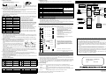
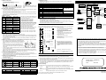
Please use the following program as a guide whenever you use the FX2N-1HC unit. Other instructions to
read the current value of the counter, status etc. can be added as required.
M11
•
BFM #4 b0
4. EXAMPLE PROGRAM
M8000
BFM #4
b9,b10
Count start
for YS output
T0 Comparision data
BFM#15,#14
*1
re
YH, YS output will not turn ON if you use PRESET or the TO
instruction to set the counter value equal to the comparison
value. It will turn ON only when a match occurs by the counting of
input pulses.
Current value
Matched
T0
ur
C
•
After comparing the current value of the counter with the value
written in BFM #13 and #12, BFM #15 and #14, the hardware and
software comparator in the FX2N-1HC outputs the comparison
result.
BFM #4 b1
Count pulse
DISABLE
11) Model identification code number BFM #30
The identification number for a Special Function Block is read by using the FROM command.
The identification number for the FX 2N-1HC unit is K4010.
By reading this identification number, the user may create built-in checking routines to check whether
the physical position of the FX2N-1HC matches to that of the software.
5) BFM #13, #12 Comparison value for YH output, BFM #15, #14 Comparison value for YS output
•
Reset
BFM #4 b8
for YH output
T0 Comparisor data
BFM #13,#12
Undefined
X 014
Data to used as the initial value when the counter starts to count.
Error status
BFM #29
DOWN/UP
There error flags can be reset by b8 of BFM #4.
4) BFM #11, #10 Preset data
•
ØB
ØA
When the upper or lower limit is
exceeded on a 32-bit counter.
b6
16-bit
counter
1-phase
1-input
counter
When value ≥ ring length in
16-bit counter mode.
When you are writing a positive value between K32,768 and K65,535, the data should be treated as a
32-bit value even when a 16-bit ring counter is used.
3) BFM #4 Command
T0 Counter mode BFM #0
Ring upper limit value
BFM #3,#2
DOWN/UP command
BFM #1
Error status
b0
In the above example, K100 is written into BFMs #3 and
#2 of special block No.2 as a 32-bit binary value (BFM
#3 = 0, BFM #2 = 100). Permitted values: K2 to K65,536.
6. SYSTEM BLOCK DIAGRAM
6. Note that counting only occurs if count prohibit is
OFF. Also, outputs will not be set from the counting
process at all if the relevant output prohibit are set in
the command register. Please reset the error flags
and YH/YS output before you start. The mutual reset
and preset initialization commands can be used as
required.
7. (M25 to M10) →BFM #4 (b15 to b0) command
8. BFM (#21, #20)→Reads the current value to the data
registers D3 and D2.
5. DIAGNOSTICS
•
This manual has been written to be used by trained and competent personnel. This is defined
by the European directives for machinery, low voltage and EMC.
•
If in doubt at any stage during the installation of the FX2N-1HC always consult a professional
electrical engineer who is qualified and trained to the local and national standards. If in doubt
about the operation or use of the FX2N-1HC please consult the nearest Mitsubishi Electric
distributor.
•
Under no circumstances will Mitsubishi Electric be liable or responsible for any consequential
damage that may arise as a result of the installation or use of this equipment.
•
All examples and diagrams shown in this manual are intended only as an aid to understanding
the text, not to guarantee operation. Mitsubishi Electric will accept no responsibility for actual
use of the product based on these illustrative examples.
•
Owing to the very great variety in possible application of this equipment, you must satisfy
yourself as to its suitability for your specific application.
5.1 Preliminary checks
1) Check that the I/O wiring and extension cable of the FX2N-1HC are properly connected.
2) 5V 90mA power is supplied from the main or extension units for the FX2N-1HC. Check that there is no
power overload from this and other extension blocks.
Manual number : JY992D65401
3) The counter works correctly only when data such as the counter mode (set with a pulse command),
the TO command, the compare value, etc. are appropriately specified. Remember to initialize the
count (BFM #4 b0), preset (BFM #4 b4), and output (BFM #4 b2, b1) prohibits. Reset the YH/YS
outputs before you start.
Manual revision : C
Date
5.2 Error checking
: JULY 2000
The following LEDs on the main panel of the FX2N-1HC may help you to troubleshoot the unit.
•
φA, φB
:Goes on/off as φA, φB input turn ON/OFF. It can be checked by rotating the encoder
slowly.
•
UP, DN
:Lights up to indicate whether the counter is going up (UP) or down (DN).
•
PRESET and DIS:The appropriate LED lights up when the PRESET terminal or the DISABLE terminal
is ON.
•
YH, YS
:The appropriate LED lights up when YH/YS output is turned on.
You can check the error status by reading the content of BFM #29 to the PLC.
Error contents are shown in section 3.3 (10).
HEAD OFFICE : MITSUBISHI DENKI BLDG MARUNOUTI TOKYO 100-8310
HIMEJI WORKS : 840, CHIYODA CHO, HIMEJI, JAPAN
JY992D65401C
TELEX : J24532 CABLE MELCO TOKYO
Effective JUL. 2000
Specifications are subject to
change without notice