1
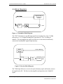
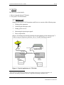
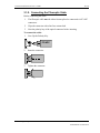
7320 Interfacility Link Installation and User’s Guide Copyright 2000 7320 IFL Installation and User’s Guide Corporate Headquarters 600 College Road East Princeton, New Jersey 08540 USA Tel: 609-514-1800 Toll Free: 1-866-OnePath Fax: 609-514-1881 Research and Development Beck Science Center 8 Hartom Street, Har-Hotzvim P.O. Box 45092 Jerusalem 91450 Israel Tel: +972-2-589-9888 Fax: +972-2-589-9898 Website: www.onepathnet.com e-mail: [email protected] This manual contains PROPRIETARY and CONFIDENTIAL information of OnePath Networks Inc. Reproduction, release to any third party, or any other unauthorized use, of any information contained herein is expressly prohibited. Foxcom Proprietary Information 2 Document No. 93-005-28-C 7320 IFL Installation and User’s Guide Table of Contents 1. Front Chapter.......................................................................................................................5 1.1 Warranty and Repair Policy .............................................................................................5 1.2 Reporting Defects.............................................................................................................6 1.3 Certification .....................................................................................................................7 1.4 Conventions .....................................................................................................................7 1.5 Precautions .......................................................................................................................7 2. Introduction to the 7320 IFL...............................................................................................9 2.1 Options .............................................................................................................................9 2.2 Product Drawings...........................................................................................................10 2.3 Block Diagrams..............................................................................................................11 3. Set Up ..................................................................................................................................12 3.1 Setting Up ......................................................................................................................12 3.2 Panel Descriptions..........................................................................................................17 4. Product Technical Description .........................................................................................18 4.1 7320 IFL Specifications .................................................................................................18 4.2 Alarm Pinouts ................................................................................................................19 4.3 Model Dimensions .........................................................................................................22 5. Manual Gain Control ........................................................................................................23 5.1 Transmitter Gain Control ...............................................................................................23 5.2 Receiver Gain Control ...................................................................................................23 6. Trouble Shooting................................................................................................................24 7. Appendix I Cleaning Fiberoptic Connections .................................................................26 8. Appendix II Installing a Standalone Unit........................................................................26 Foxcom Proprietary Information 3 Document No. 93-005-28-C 7320 IFL Installation and User’s Guide List of Figures Figure 1 - System 7320 Transmitter Front and Rear Panels ....................................................10 Figure 2 - System 7320 Receiver Front and Rear Panels.........................................................10 Figure 3 - Transmitter Block Diagram.....................................................................................11 Figure 4 - Receiver Block Diagram .........................................................................................11 Figure 5 - Basic Setup of a System 7320 .................................................................................12 Figure 6 - System 7320 Transmitter Pinout .............................................................................20 Figure 7 - System 7320 Receiver Pinout..................................................................................21 List of Tables Table 1 - 7320 Transmitter LEDs ............................................................................................17 Table 2 - 7320 Receiver LEDs.................................................................................................17 Table 3 - 7320T Transmitter Pinout.........................................................................................20 Table 4 - 7320R Receiver Pinout.............................................................................................21 Table 5 - Receiver RF Signal Voltage .....................................................................................23 Table 6 - Trouble Shooting ......................................................................................................24 Foxcom Proprietary Information 4 Document No. 93-005-28-C 7320 IFL Installation and User’s Guide Front Chapter 1. Front Chapter 1.1 Warranty and Repair Policy Foxcom performs testing and inspection to verify the quality and reliability of our products. Foxcom uses every reasonable precaution to ensure that each unit meets specifications before shipment. Customers are asked to advise their incoming inspection, assembly, and test personnel as to the precautions required in handling and testing our products. Many of these precautions are to be found in this manual. Nullification of Warranty The Warranty is null and void if the product casing is opened. The products are covered by the following warranties: A) General Warranty Foxcom warrants to the original purchaser all standard products sold by Foxcom to be free of defects in material and workmanship for one (1) year from date of shipment from Foxcom. During the warranty period, Foxcom will repair or replace any product that Foxcom proves to be defective. This warranty does not apply to any product which has been subject to alteration, abuse, improper installation or application, accident, electrical or environmental over-stress, negligence in use, storage, transportation or handling. B) Specific Product Warranty Instructions All Foxcom products are warranted against defects in workmanship, materials and construction, and to no further extent. Any claim for repair or replacement of units found to be defective on incoming inspection by a customer must be made within 30 days of receipt of shipment, or within 30 days of discovery of a defect within the warranty period. This warranty is the only warranty made by Foxcom and is in lieu of all other warranties, expressed or implied. Foxcom sales agents or representatives are not authorized to make commitments on warranty returns. Foxcom Proprietary Information 5 Document No. 93-005-28-C 7320 IFL Installation and User’s Guide Front Chapter C) Returns In the event that it is necessary to return any product against above warranty, the following procedure shall be followed: 1. Return authorization is to be received from Foxcom prior to returning any unit. Advise Foxcom of the model, serial number, and discrepancy. The unit may then be forwarded to Foxcom, transportation prepaid. Devices returned collect or without authorization may not be accepted. 2. Prior to repair, Foxcom will advise the customer of our test results and any charges for repairing customer-caused problems or out-of-warranty conditions etc. 3. Repaired products are warranted for the balance of the original warranty period, or at least 90 days from date of shipment. D) Limitations of Liabilities Foxcom's liability on any claim, of any kind, including negligence for any loss or damage arising from, connected with, or resulting from the purchase order, contract, quotation, or from the performance or breach thereof, or from the design, manufacture, sale, delivery, installation, inspection, operation or use of any equipment covered by or furnished under this contact, shall in no case exceed the purchase price of the device which gives rise to the claim. EXCEPT AS EXPRESSLY PROVIDED HEREIN, FOXCOM MAKES NO WARRANTY, EXPRESSED OR IMPLIED, WITH RESPECT TO ANY GOODS, PARTS AND SERVICES PROVIDED IN CONNECTION WITH THIS AGREEMENT INCLUDING, BUT NOT LIMITED TO, THE IMPLIED WARRANTIES OF MERCHANTABILITY AND FITNESS FOR A PARTICULAR PURPOSE. FOXCOM SHALL NOT BE LIABLE FOR ANY OTHER DAMAGE INCLUDING, BUT NOT LIMITED TO, INDIRECT, SPECIAL OR CONSEQUENTIAL DAMAGES ARISING OUT OF OR IN CONNECTION WITH FURNISHING OF GOODS, PARTS AND SERVICE HEREUNDER, OR THE PERFORMANCE, USE OF, OR INABILITY TO USE THE GOODS, PARTS AND SERVICE. 1.2 Reporting Defects The units were inspected before shipment and found to be free of mechanical and electrical defects. Examine the units for any damage which may have been caused in transit. If damage is discovered, file a claim with the freight carrier immediately. Notify Foxcom as soon as possible. Note Keep all packing material until you have completed the inspection. Foxcom Proprietary Information 6 Document No. 93-005-28-C 7320 IFL Installation and User’s Guide Front Chapter 1.3 Certification The 7320 IFL has CE, FCC, FDA, and UL certification. 1.4 Conventions In this manual the following special formats are used: Note Notes contain information detailing the current topic. CAUTION Cautions contain information regarding situations or materials which could damage your product. WARNING WARNINGS CONTAINS INFORMATION REGARDING DANGEROUS FUNCTIONS. 1.5 Precautions 1.5.1. Personal Safety WARNING OPTICAL RADIATION APPLYING POWER TO THE TRANSMITTER UNIT WILL CREATE A LASER ENERGY SOURCE OPERATING IN CLASS I AS DEFINED BY IEC 825-1. USE EITHER AN INFRARED VIEWER, OPTICAL POWER METER OR FLUORESCENT SCREEN FOR OPTICAL OUTPUT VERIFICATION. AC POWER HAZARD THE RACKMOUNT POWER SUPPLY LINE IS EMI FILTERED AND FUSED. THE CHASSIS IS CONNECTED TO EARTH GROUND IN COMPLIANCE WITH SAFETY REQUIREMENTS. ALWAYS USE THE 3 PRONG AC PLUG WITH EARTH GROUND TO AVOID POSSIBILITY OF ELECTRICAL SHOCK HAZARD TO PERSONNEL. Foxcom Proprietary Information 7 Document No. 93-005-28-C 7320 IFL Installation and User’s Guide Front Chapter 1.5.2. Equipment Safety To avoid damaging your product, please observe the following: 1. Fuses: To avoid possibility of fire hazard, always replace fuses with the same type and rating of fuse as recommended on the power supply rear label. 2. The input of the transmitter has an optional built-in bias for inserting DC power up the coax to the LNB. Make certain any equipment or test equipment connected to the transmitter input can withstand this bias. 3. The output of the receiver is AC coupled and can withstand the bias from a satellite receiver. Do not exceed 25V DC bias. 4. Do not allow any dirt or foreign material to get into the optical connector bulkheads. This may cause damage to the polished optical connector end faces. 5. The optical fiber jumper cable bend radius is 3 cm. Smaller radii can cause excessive optical loss and/or fiber breakage. 6. If multiple transmitters are installed in the chassis allow sufficient room for adequate ventilation; otherwise the units may overheat causing possible safety hazard or equipment damage. 7. When several units are installed on one 7000M chassis, ensure that the total units’ current (including any LNB bias) does not exceed 2A per power supply (e.g. if there are two power supplies the current should not exceed 4A.) Foxcom Proprietary Information 8 Document No. 93-005-28-C 7320 IFL Installation and User’s Guide Introduction to the 7320 IFL 2. Introduction to the 7320 IFL The Sat-Light 7320 IFL transmits an L-Band RF signal over singlemode fiber from a satellite antenna LNB to control room equipment up to two kilometers away. The 7320 IFL consists of an optical transmitter (7320T) which receives the L-Band signal from the LNB and an optical receiver (7320R) which connects to a satellite receiver. The 7320T and 7320R modules plug into a 7000M 3U chassis/power supply which enables expansion of the system to accommodate any 6 Sat-Light modules. Accessories include the Model 7000S Standby Power Supply, the Model 2000 1:1 Redundant Switch, the Model 2100 Amplifier, and the Model 7050-4 Serial Data Multiplexer, an asynchronous data link. The 7320 IFL is a broadband transmission link; all standard satellite modulation formulas can be transmitted (i.e. QPSK, FM, etc.).. The RF signal is directly modulated and adds virtually no phase noise to the original signal. The direct modulation, coupled with the 7320 Links RF circuitry, guarantees superior signal quality. The 7320 gives more than 25 dB carrier to noise performance in a full multichannel environment. Gain Control provides for optimization of the RF signal. LEDs, and back panel monitors and alarms allow for complete system status monitoring and for interfacing with M & C systems. 2.1 Options The 7320 IFL comes with a variety of options: 1. LNB powering - The transmitter unit can provide 15 VDC for optional LNB powering. 2. 50 Ω Input/Output Impedance/BNC RF connector. Standard impedance is 75 Ω/F type, female connectors are standard. 3. Standalone unit - The 7320 IFL can be installed as a standalone unit. If the 7320 is used as a standalone, a separate power supply must be used. On the side of the 7320T and the 7320R units is a sticker1 which lists options 1 & 2. Under each option is a square. If the unit includes a particular option the square under the option should be marked. For example in Figure 1 the LNB option is marked. Options 1550 LNB 50 25 Figure 1 - Option Sticker 1 The sticker includes options which are not relevant to the 7320 IFL. Foxcom Proprietary Information 9 Document No. 93-005-28-C 7320 IFL Installation and User’s Guide Introduction to the 7320 IFL 2.2 Product Drawings Figure 2 shows the front and rear panels of the System 7320 Transmitter units. 7320T Figure 2 - System 7320 Transmitter Front and Rear Panels Figure 3 shows the front and rear panels of the System 7320 Receiver units. 7320R Figure 3 - System 7320 Receiver Front and Rear Panels Foxcom Proprietary Information 10 Document No. 93-005-28-C 7320 IFL Installation and User’s Guide Introduction to the 7320 IFL 2.3 Block Diagrams Optical Power & Temperature Control PreAmp Laser Figure 4 - Transmitter Block Diagram The 7320T Transmitter accepts RF input signal levels ranging from -40 to -20 dBm total power (i.e. at 10 channel loading this is equivalent to -50 to -30 dBm per channel). The unit amplifies the signal, and feeds it to a laser diode which linearly converts the broadband RF signal to light intensity. Bias & Optical Power Monitor Photodiode Power & Monitors Preamp Gain Control Postamp Output Figure 5 - Receiver Block Diagram The 7320R Optical Receiver receives the optical intensity signal, and linearly converts the signal back to RF. The Receiver then amplifies and reproduces the L-Band RF signal. Foxcom Proprietary Information 11 Document No. 93-005-28-C 7320 IFL Installation and User’s Guide Set Up 3. Set Up The following section details: • How to setup the System 7320 units • The System 7320 Front Panels 3.1 Setting Up2 Setting up the System 7320 Transmitters and Receivers consists of the following steps: 1. Setting up the transmitter. 2. Connecting the fiberoptic cable. 3. Setting up the receiver. 4. Monitoring the input/output signals. 5. Power requirements. Observe all warnings and cautions mentioned at the beginning of this manual (page 7). If after set-up you experience problems, refer to Trouble Shooting on page 24. Figure 6 - Typical Application of a 7320 Link 2 This section gives instructions on installing the transmitter and receiver in a chassis rackmount. For instructions on installing a standalone unit refer to Appendix II Installing a Standalone Unit. Foxcom Proprietary Information 12 Document No. 93-005-28-C 7320 IFL Installation and User’s Guide Set Up 3.1.1. Setting Up the Transmitter 1. Place the 7320T in the 7000M Chassis. The operating base plate temperature must be between -10° C to 55° C. 2. Apply AC power to the chassis. The Power Supply’s LED should be lit. 3. Mount the 7320T into the chassis. The Laser LED should be lit. 4. Using an optical power meter, measure the optical power. Insert the meter’s cable into the Transmitter’s optical connector. Power levels should be between 0.3 - 1 mW. Alternatively, use a DVM to measure the voltage at pin #6 on the back panel connector. The power level should be -4.5 ± 0.3 VDC. 5. On the rear panel, connect the coax cable to the RF Input Connector. 6. On the rear panel, connect the fiberoptic cable to the Optical Connector. Note If either LED is not lit, refer to Trouble Shooting on page 24. Foxcom Proprietary Information 13 Document No. 93-005-28-C 7320 IFL Installation and User’s Guide Set Up 3.1.2. Connecting the Fiberoptic Cable Before connecting the cable: 1. The fiberoptic cable must be either fusion spliced or connected via FC/APC connectors. 2. Wipe the connector with a lint-free cotton cloth. 3. Note the polarity key of the optical connector before inserting. To connect the cable: 1. Line Up the Polarity Key. FC/APC 2. Insert the connector. 3. Tighten the connector. Foxcom Proprietary Information 14 Document No. 93-005-28-C 7320 IFL Installation and User’s Guide Set Up 3.1.3. Setting Up the Receiver 1. Place the 7320 Receiver in the 7000M Chassis. The operating base plate temperature must be between -10° C to 55° C. 2. Apply AC power to the chassis. The Power Supply’s LED should be lit. 3. Mount the 7320R into the chassis. 4. On the rear panel connect the fiberoptic cable to the Optical Connector. The Opt. LED should be lit. 5. Using an optical power meter, measure the optical power coming to the Receiver from the fiberoptic cable. The power levels of the Receiver should be the power level measured at the Transmitter minus the fiber loss3. Alternatively, use a DVM to measure the voltage at pin #6 of the D type connector. The power level should be 1V to each 1 mW measured at the Receiver input. 6. On the rear panel, connect the fiberoptic cable to the Optical Connector. The Opt. LED should be lit. 7. On the rear panel, connect the coax cable to the RF Output Connector. Note If either LED is not lit, refer to Trouble Shooting on page 24. 3.1.4. Measuring the RF Signal Strength The Receiver’s RF signal strength can be monitored during operation via a DC RF signal-strength monitor. Maintenance personnel can perform a simple verification process. To measure the RF signal strength: 1. Using a Digital Volt Meter, measure the voltage at the connector pin #4 (both Rackmount or Standalone). 2. Refer to Manual Gain Control on page 23 for further details regarding voltage levels. 3 Fiber loss is defined as: (0.4 dB/km x length (km) of the fiberoptic cable) + (0.5 dB x number of connectors). For example if a link was 10 kilometers long and had two connectors the loss would be: (0.4 dB/km x 10 km) + (0.5 dB x 2) = 5.0 dB. Foxcom Proprietary Information 15 Document No. 93-005-28-C 7320 IFL Installation and User’s Guide Set Up 3.1.5. Powering the IFL • Transmitter power requirement - 15VDC @ 300 mA (excluding LNB Drive Option) Receiver power requirement - 15VDC @ 230 mA The Standalone Transmitter/Receiver can be powered by a Foxcom-supplied external DC power supply. The Rackmount Transmitters/Receivers are plugged into the 7000M rackmount chassis. The chassis can accept and power up to six units. • • • Note At temperatures below 10° C, the Transmitter’s internal heater will require an additional 100 mA. The Transmitter’s total power requirement will then be 400 mA. CAUTION Ensure that there is a good airflow around the chassis rackmount. 7000M Chassis The 7000M Chassis provides power to the plug in units. The power supply is a linear unregulated type. Each plug in unit regulates its own voltage. The 7000M provides: • • • • 15 -18 VDC (unregulated) @ 2.2 amps power AC input @ 110/220 VAC (user selected) Units can be plugged in “hot standby” An internal 5 amp fuse 7000S (optional) Hot standby power supply For applications demanding the utmost in reliability and uptime, the 7000S standby power supply can be optionally plugged in to the standard chassis. The 7000S features hot swapping - supplies may be installed and removed even during operation. Each power supply is fully redundant and can power a completely loaded chassis on its own should its "partner" fail. During normal operation the two units share the load by means of current steering diodes located on the rear panel. Foxcom Proprietary Information 16 Document No. 93-005-28-C 7320 IFL Installation and User’s Guide Set Up 3.2 Panel Descriptions On the Front Panel of the 7320 Transmitter and Receiver unit are two LEDs. The following tables describe the LEDs. Table 1 - 7320 Transmitter LEDs LED Name Laser RF LED Function Indicates if the optical output power control is functioning Indicates if the RF signal is above the minimal level Table 2 - 7320 Receiver LEDs LED Name Opt. RF Foxcom Proprietary Information LED Function Indicates if the optical reception power is within limits Indicates if the RF signal is above the minimal level 17 Document No. 93-005-28-C 7320 IFL Installation and User’s Guide Product Technical Description 4. Product Technical Description • • • • 7320 IFL specifications Alarm and Monitor Pinouts Model Dimensions 7320 IFL Front Panels 4.1 7320 IFL Specifications RF Characteristics Frequency Range Flatness Input/Output Impedance Input VSWR Output VSWR Input Signal Range (Total Power) Output Signal Range (Total Power) CNR Link Gain Gain Control RF Connector Optical Characteristics Optical Wavelength Optical Power Output Optical Link Budget Optical Connector Receiver Sensitivity Miscellaneous Chassis Capacity Chassis Size Plug-in Unit size Power for Chassis Power for Standalone Transmitter Receiver Operating Temperature Range Storage Temperature Foxcom Proprietary Information 950 -2150 MHz ± 2.0 dB (typical); ± 2.5 dB (max.) 75 Ω (50 Ω optional) 2:1 (max.) 2:1 (max.) -40 to -20 dBm -45 to -15 dBm >30 dB in 35 MHz BW (single channel) adjustable ± 10 dB Manual F type female (BNC - optional) 1310 ± 10 nm 0.2 - 0.5 mW 3 dB/ 2 km (min.) FC/APC (or fusion splice) -9 dBm optical (min.) 6 plug-ins 19” x 3U x 7” 5.1” x 4.9” x 1.6” 110 or 220 VAC 15 VDC @ 300 mA (max.) (400 mA < 100 C) 15 VDC @ 210 mA (max.) -10° C to 55° C -20° C to 85° C 18 Document No. 93-005-28-C 7320 IFL Installation and User’s Guide Product Technical Description 4.2 Alarm Pinouts The unit’s pins are found at the backplane of the 7000M chassis. The 7000M backplane incorporates 6 slots, each of which has its own 6 pin blank header associated with it. Any monitor voltages to be measured may be done between the chassis ground and the required pin. The pins are numbered as follows: 6 5 4 3 2 1 Foxcom Proprietary Information 19 Document No. 93-005-28-C 7320 IFL Installation and User’s Guide Product Technical Description Table 3 - 7320T Transmitter Pinout Standalone 9 Pin Connector 1 2 3 4 Rackmount 6 Pin Back Panel Connector Function Description 300 mA4 (excluding LNB Option) 6 +15V Power Not Used Power Ground RF Signal Strength Monitor PDI 5 6 1 LSRI 7 2 RF Alarm 8 3 LSR Alarm 9 5 LNB Bias (optional) 4 DC Return RF Signal Strength Indicator; Range 2 - 10V Measures Laser Optical Power; Range -3.0 to -4V Measures Laser Bias; Range -4.5 ± 0.2V Open collector interface. Sinks current when RF level is low. Open collector interface. Sinks current when optical level is low. External LNB Bias 7320T Transmitter 9 Pin D-Type Male Connecter Not Used RF Signal Strength Monitor Laser Photodiode Current Monitor Laser Current Monitor AGC Alarm LSR Alarm 1 2 3 4 5 6 +15V Power Power Ground 7 8 9 External LNB Bias Figure 7 - System 7320 Transmitter Pinout 4 400 mA below 100 C Foxcom Proprietary Information 20 Document No. 93-005-28-C 7320 IFL Installation and User’s Guide Product Technical Description Table 4 - 7320R Receiver Pinout Standalone 9 Pin Connector 1 2 3 4 Rackmount 6 Pin Back Panel Connector Function Description 230 mA 1 2 +15V Not Used Power Ground RF Signal Strength Monitor Optical Power Input Level Monitor Spare RF Alarm 5 6 6 7 8 3 Optical Power Alarm 9 5 Spare 4 DC Return RF Signal Strength Indicator; Range 0.25 to 2V 1V/mW Optical Power Received Not Used Open collector interface. Sinks current when RF level is low. Open collector interface. Sinks current when optical level is low. Not Used 7320R Receiver 9 Pin D-Type Male Connecter Not Used 1 2 RF Signal Strength Monitor Optical Power Monitor 3 4 5 6 Not Used AGC Alarm Optical Alarm Not Used +15V Power Power Ground 7 8 9 Figure 8 - System 7320 Receiver Pinout CAUTION When monitoring the voltage outputs use only a high resistance DVM. Foxcom Proprietary Information 21 Document No. 93-005-28-C 7320 IFL Installation and User’s Guide Product Technical Description 4.3 Model Dimensions Optical RF Test Gain Control 4" 3.69" RF DCPower 3" 0.06" 4.9" Figure 9 - Unit Dimensions 0.12“ FRONT VIEW 1.52’‘ “ REAR VIEW Figure 10 - Chassis Dimensions Foxcom Proprietary Information 22 Document No. 93-005-28-C 7320 IFL Installation and User’s Guide Manual Gain Control 5. Manual Gain Control All internal adjustments have been set up at the factory; the only user adjustments are input and output RF signal levels accessible from the front panel and described in the following sections. 5.1 Transmitter Gain Control Since MGC sets a constant input gain to the laser, an initial setup is required to ensure the input signal level is not too high (over-driving the laser) or too low (noisy). These variations can be caused by changes in dish pointing, rain fade or satellite channel loading, or any other reason. To prevent under-driving or over-driving the laser the signal level must be between 2 to 5VDC. To set the Transmitter MGC: 1. Adjust the MGC potentiometer while monitoring the RF signal voltage. The 7320 IFL is designed to provide optimal output at 2.5V ± 0.5V. Therefore regardless of the input the Manual Gain Control should be set to provide this output. 2. If there is input signal level variation expected, it is best to leave some "headroom" should the signal level become too strong and result in distortion. It is usually better to adjust the signal lower rather than higher. 5.2 Receiver Gain Control Receiver Gain Control allows the user to set the output signal levels. The Gain potentiometer is adjusted while monitoring the voltage of the Receiver "RF Sig." Monitor (Pin #4 on the 6 Pin Connector). The chart below provides approximate settings for desired output levels. Table 5 - Receiver RF Signal Voltage RF Output Level -15 dBm -20 dBm -30 dBm -35 dBm Foxcom Proprietary Information RF Signal Voltage Setting 9.0V ± 1 4.0V ± 0.5 0.75V ± 0.2 0.225V ± 0.02 23 Document No. 93-005-28-C 7320 IFL Installation and User’s Guide Trouble Shooting 6. Trouble Shooting The System 7320 was tested before it left the factory. However if you are experiencing difficulties consult the list below for possible solutions. If your system is still experiencing problems, please attempt to isolate and identify the malfunctioning unit. Table 6 - Trouble Shooting PROBLEM POSSIBLE CAUSE 1. Laser LED not on 1. No DC power to the unit. Possible power supply problem or AC power input problem. Check the fuse. 2. Verify LSRI monitor is -4.5V ± 0.3. If not, laser may have overheated. Disconnect power or remove plug in and allow to cool. Try again with better airflow. 3. If an optical power meter is available, measure the optical power out of the transmitter. The power should be 0.3 mW to 1 mW. If an optical power meter is not available, then use another receiver to determine if there is optical power emerging from the transmitter (use the 5 meter jumper cable). If there is no optical power, then the transmitter unit is malfunctioning. If any or all the above are not within the guidelines, the transmitter unit is faulty. 2. Lack of RF signal present at Receiver, yet optical power is functioning. 1. If the unit has an LNB drive option, verify that the correct LNB bias is coming down the center of the RF connector at the transmit site. 2. Verify that the dish is pointed and correctly receiving satellite signals. Conclusion: If signal still not present then Transmitter input stage amplifier is defective. Contact Foxcom. 3. No optical power, LED not illuminated. 1. There is a break or severe bend in the fiberoptic cable. Use an optical power meter or another functioning receiver unit to verify optical power coming down the fiber. 2. Optical power too low, too many splits, too long a distance (thus exceeding optical budget). System may still function without LED illuminated although at reduced performance. 3. The transmitter is not functioning, see above. Foxcom Proprietary Information 24 Document No. 93-005-28-C 7320 IFL Installation and User’s Guide Trouble Shooting PROBLEM POSSIBLE CAUSE 4. Damaged (leaky) photodiode. Unit may still function, otherwise contact Factory for service. Optical power light illuminated with disconnected optical input. Foxcom Proprietary Information 25 Document No. 93-005-28-C 7320 IFL Installation and User’s Guide Appendix I Cleaning Fiberoptic Connections 7. Appendix I Cleaning Fiberoptic Connections The unit has an FC/APC (or other optional) optical connector for very high optical return loss performance. The units are specified into singlemode fiber i.e. 9/125 micron core diameter. Full performance is specified only for low return loss optical plant - meaning that the fiber must be fusion spliced and all connections or splices must have a return loss greater than -60 dB. With these guidelines in mind, link lengths beyond 20 kilometers. (DFB based products) can be achieved with high performance. Specific performance and/or design assistance is available by request from Foxcom. If there is low/no signal or noisy signal at a Foxcom module, the connector should be cleaned. Dirt on the inside connector tip can impair the flow of light causing problems in signal transmission. Foxcom modules are sealed but dirt can occasionally enter. 8. Appendix II Installing a Standalone Unit To install the 7320T or 7320R Standalone: 1. Place the 7320 unit on the standalone flange, matching the holes. 2. Using four screws (#4 or #6) secure the unit and the flange to the wall. 3. Apply AC power to the standalone power supply unit. 4. Connect the 7320 unit to the power supply. The Laser LED should be lit. 5. All remaining steps are the same. Refer to Setting Up the Transmitter on page 13, and Setting Up the Receiver on page 15. Foxcom Proprietary Information 26 Document No. 93-005-28-C