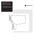
1
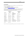
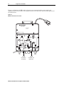
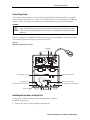
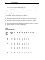
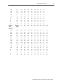
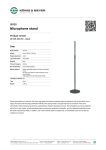
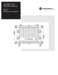
Installation Manual Broadband House Amplifier BHA-100S/P-R BHA-100K/P-R BHA-100A/P-R 101 Tournament Drive Horsham, PA 19044 POWER SUPPLY 100 - 240 VAC SERIAL NO. 870 MHz BROADBAND HOUSE AMPLIFIER BHA-87S/P 1003 MHz BROADBAND HOUSE AMPLIFIER BHA-87K/P BHA-87A/P FORWARD EQ BHA-100S/P-R +24 VDC TEST POINT BHA-100K/P-R SLOPE GAIN FORWARD JXP POWER BHA-100A/P-R -20 dB REVERSE INPUT TEST POINT RETURN JXP H L L H RETURN EQ RETURN JXP -20 dB REVERSE OUTPUT TEST POINT IN -20 dB FORWARD IN TEST POINT -20 dB FORWARD OUT TEST POINT CAUTION: CONTAINS PARTS AND ASSEMBLIES SUSCEPTIBLE TO DAMAGE BY ELECTROSTATIC DISCHARGE (ESD) OUT IMPORTANT SAFEGUARDS 12. Power-cord Protection — Power-supply cords should be routed so 1. Read instructions — All the safety and operating instructions that they are not likely to be walked on or pinched by items placed upon or against them, paying particular attention to cords at plugs, should be read before the appliance is operated. convenience receptacles, and the point where they exit from the 2. Retain instructions — The safety and operating instructions appliance. should be retained for future reference. 13. Outdoor antenna grounding — If an outside antenna or cable system 3. Heed Warnings — All warnings on the appliance and in the is connected to the video product, be sure the antenna or cable system operating instructions should be adhered to. is grounded so as to provide some protection against voltage surges 4. Follow instructions — All operating and use instructions and built-up static charges. Section 810 of the National Electrical should be followed. Code, ANSI/NFPA, No. 70-1984, provides information with respect 5. Cleaning — Unplug this video product from the wall outlet to proper grounding of the mast and supporting structure, grounding before cleaning. Do not use liquid cleaners or aerosol of the lead-in wire to an antenna discharge unit, size of grounding cleaners. Use a damp cloth for cleaning. Exception: A product conductors, location of Antenna-discharge unit. Connection to that is meant for uninterrupted service and that for some grounding electrodes, and requirements for the grounding electrode. specific reason, such as the possibility of the loss of an See figure 75.1 auithorization code for a CATV converter, is not intended to 14. Lightning — For added protection for this video product receiver be unplugged by the user for cleaning or any other purpose, during a lightning storm, or when it is left unattended and unused for may exclude the reference to unplugging the appliance in the long periods of time, unplug it from the wall outlet and disconnect cleaning description otherwise required in item 5. the antenna or cable system. This will prevent damage to the video 6. Attachments — Do not use attachments not recommended by product due to lightning and power-line surges. the video product manufacturer, as they may cause hazards. 15. Power lines — An outside antenna system should not be located in 7. Water and Moisture — Do not use this video product near the vicinity of overhead power lines or other electric light or power water: for example, near a bath tub, wash bowl, kitchen sink, circuits, or where it can fall into such power lines or circuits. When or laundry tub, in a wet basement, near a swimming pool, and installing an outside antenna system, extreme care should be taken to the like. keep from touching such power lines of circuits, as contact with them 8. Accessories — Do not place this video product on an unstable might be fatal. cart, stand, tripod, bracket, or table. The video product may 16. Overloading — Do not overload wall outlets and extension cords, as fall, causing serious injury to a child or adult, and serious this can result in a risk of fire or electric shock. damage to the appliance. Use only with a cart, stand, tripod, 17. Object and liquid Entry — never push objects of any kind into this bracket, or table recommended by the manufacturer, or sold video product through openings, as they may touch dangerous with the video product. Any mounting of the appliance should voltage points or short-out parts that could result in a fire or electric follow the manufacturer's instructions, and should use a shock. Never spill liquid of any kind on the video-product. mounting accessory recommended by the manufacturer. 9. Ventilation — Slots and openings in the cabinet are provided 18. Servicing — Do not attempt to service this video product yourself, as opening or removing covers may expose you to dangerous voltage for ventilation and to ensure reliable operation of the video or other hazards. Refer all servicing to qualified service personnel. product and to protect it from overheating, and these openings 19. Damage requiring service-unplug this video product from the wall must not be blocked or covered. The openings should never be outlet and refer servicing to qualified service personnel under the blocked by placing the video product on a bed, sofa, rug, or following conditions: other similar surface. This video product should never be a. When the power-supply cord or plug is damaged. placed near or over a radiator or heat register. This video b. If liquid has been spilled or objects have fallen into the video product should not be placed in a build-in installation such as product. a bookcase or rack unless proper ventilation is provided or the c. If the video product has been exposed to rain or water. manufacturer's instructions have been adhered to. d. If the video product does not operate normally by following the 10. Power Sources — This video product should be operated operating instructions. Adjust only those controls that are covered only from the type of power source indicated on the by the operating instructions, as an improper adjustment of other marketing label. If you are not sure of the type of power controls may result in damage and will often require extensive supply to your home, consult your appliance dealer or local work by a qualified technician to restore the video product to its power company. For video products intended to operate from normal operation. battery power, or other sources, refer to the operating e. If the video product has been dropped or the cabinet has been instructions. damaged. 11. This video product is equipped with a 3-wire grounding f. When the video product exhibits a distinct change in performancetype plug, a plug having a third (grounding) pin. This plug this indicates a need for service. will only fit into a ground-type power outlet. This is a safety feature.If you are unable to insert the plug into the outlet, contact your electrician to replace your obsolete outlet. Do not defeat the safety purpose of the ground-type plug. 20. Replacement parts — When replacement parts are required, be sure the service technician has used replacement parts specified by the manufacturer or have the same characteristics may result in fire, electric shock or other hazards. 21. Safety check — Upon completion of any service or repairs to this video product, ask the service technician to perform safety checks to determine that the video product is in proper operating condition. Model: BHA-100* CATV DISTRIBUTION AMPLIFIER BHA-100S/P-R BHA-100K/P-R BHA-100A/P-R Warning: To reduce the risk of fire or electric shock, do not expose this appliance to rain or moisture. Note to CATV system installer: This reminder is provided to call the CATV system installer's attention to Article 820-40 of the NEC that provides guidelines for proper grounding and in particular specifies that the cable ground shall be connected to the grounding system of the building as close to the point of cable entry as practical. CAUTION CAUTION: TO REDUCE THE RISK OF ELECTRIC SHOCK, DO NOT REMOVE COVER(OR BACK) NO USER-SERVICEABLE PARTS INSIDE REFER SERVICING TO QUALIFIED SERVICE PERSONNEL Caution These servicing instructions are for use by qualified personnel only. To reduce the risk of electrical shock, do not perform any servicing other than that contained in the Installation and Troubleshooting Instructions unless you are qualified to do so. Refer all servicing to qualified service personnel. Special Symbols That Might Appear on the Equipment This symbol indicates that dangerous voltage levels are present within the equipment. These voltages are not insulated and may be of sufficient strength to cause serious bodily injury when touched. The symbol may also appear on schematics. The exclamation point, within an equilateral triangle, is intended to alert the user to the presence of important installation, servicing, and operating instructions in the documents accompanying the equipment. For continued protection against fire, replace all fuses only with fuses having the same electrical ratings marked at the location of the fuse. FCC Compliance This equipment has been tested and found to comply with the limits for a Class A digital device, pursuant to Part 15 of the FCC Rules. These limits are designed to provide reasonable protection against harmful interference when the equipment is operated in a commercial environment. This equipment generates, uses, and can radiate radio frequency energy and, if not installed and used in accordance with the Installation Manual, may cause harmful interference to radio communications. Operation of this equipment in a residential area is likely to cause harmful interference in which case the user will be required to correct the interference at his/her own expense. CAUTION: Any changes or modifications not expressly approved by Motorola could void the user’s authority to operate this equipment under the rules and regulations of the FCC. Canadian Compliance This Class A digital device complies with Canadian ICES-003. Cet appareil numérique de la classe A est conforme À la norme NMB-003 du Canada. FCC Declaration of Conformity According to 47 CFR, Parts 2 and 15 for Class B Personal Computers and Peripherals; and/or CPU Boards and Power Supplies used with Class B Personal Computers, Motorola, Inc., 6450 Sequence Drive, San Diego, CA 92121, 1-800-225-9446 or 101 Tournament Drive, Horsham, PA 19044, 1-800-523-6678, declares under sole responsibility that the product identifies with 47 CFR Part 2 and 15 of the FCC Rules as a Class B digital device. Each product marketed is identical to the representative unit tested and founded to be compliant with the standards. Records maintained continue to reflect the equipment being produced can be expected to be within the variation accepted, due to quantity production and testing on a statistical basis as required by 47 CFR 2.909. Operation is subject to the following condition: This device must accept any interference received, including interference that may cause undesired operation. The above named party is responsible for ensuring that the equipment complies with the standards of 47 CFR, Paragraphs 15.107 to 15.109 Copyright © 2008 by Motorola, Inc. All rights reserved. No part of this publication may be reproduced in any form or by any means or used to make any derivative work (such as translation, transformation or adaptation) without written permission from Motorola, Inc. Motorola reserves the right to revise this publication and to make changes in content from time to time without obligation on the part of Motorola to provide notification of such revision or change. Motorola provides this guide without warranty of any kind, either implied or expressed, including, but not limited to, the implied warranties of merchantability and fitness for a particular purpose. Motorola may make improvements or changes in the product(s) described in this manual at any time. Motorola, and the stylized M logo, are registered trademarks of Motorola, Inc. All other product or service marks are the property of their respective owners. © Motorola, Inc. 2008. Contents Section 1 Introduction Using this Manual ............................................................................................................................................................................ 1-2 Document Conventions................................................................................................................................................................... 1-2 If You Need Help............................................................................................................................................................................... 1-3 Calling for Repairs ........................................................................................................................................................................... 1-4 Section 2 Overview Power Supply ................................................................................................................................................................................... 2-2 Forward Amplifier ............................................................................................................................................................................ 2-3 Accessories and Options................................................................................................................................................................ 2-4 Return Amplifier ...................................................................................................................................................................... 2-4 Cable Equalizers...................................................................................................................................................................... 2-4 Section 3 Configuration and Installation Mounting the BHA-100* ................................................................................................................................................................... 3-1 Configuring the BHA-100*............................................................................................................................................................... 3-1 Connecting Power............................................................................................................................................................................ 3-3 Installing the Equalizer and Input Pad ........................................................................................................................................... 3-4 Determining the Equalizer...................................................................................................................................................... 3-4 Starline Cable Simulators – SCS-*......................................................................................................................................... 3-7 Installing the Return Amplifier Kit.................................................................................................................................................. 3-7 Appendix A Specifications Abbreviations and Acronyms BHA-100* Broadband House Amplifier Installation Manual ii Contents Figures Figure 1-1 BHA-100* broadband house amplifier.........................................................................................................................1-1 Figure 2-1 BHA-100* dimensions ...................................................................................................................................................2-1 Figure 2-2 BHA-100* functional block diagram ............................................................................................................................2-3 Figure 3-1 BHA-100* with outer cover removed ...........................................................................................................................3-2 Figure 3-2 BHA-100* fuse and plug-in accessories .....................................................................................................................3-3 Figure 3-3 Equalizer slope versus cable .......................................................................................................................................3-6 Tables Table 2-1 BHA-100* models ............................................................................................................................................................2-2 Table 2-2 Amplifier accessories.....................................................................................................................................................2-4 Table 3-1 Starline Forward Equalizers – SFE*-* ...........................................................................................................................3-4 Table 3-2 Starline Cable Simulators ..............................................................................................................................................3-7 Table A-1 Specifications for models BHA-100S/P-R, BHA-100K/P-R, and BHA-100A/P-R...................................................... A-1 BHA-100* Broadband House Amplifier Installation Manual Section 1 Introduction Motorola’s Broadband House Amplifier, BHA-100*, is a high performance, two-way distribution amplifier. It is designed for the sheltered environment of multiple dwelling units (MDU), such as apartment buildings, condominiums, and hospitals. The BHA-100* takes advantage of CATV technology used in extended bandwidth cable systems and is capable of two-way signal transmission with the addition of a return amplifier kit. For more information regarding this product, consult the Motorola product catalog or visit the Web site: http://broadband.motorola.com/catalog. Figure 1-1 illustrates the BHA-100*. Figure 1-1 BHA-100* broadband house amplifier 101 Tournament Drive Horsham, PA 19044 POWER SUPPLY 100 - 240 VAC SERIAL NO. 870 MHz BROADBAND HOUSE AMPLIFIER 1003 MHz BROADBAND HOUSE AMPLIFIER BHA-87S/P BHA-87K/P BHA-87A/P FORWARD EQ BHA-100S/P-R +24 VDC TEST POINT BHA-100K/P-R GAIN FORWARD JXP POWER SLOPE BHA-100A/P-R -20 dB REVERSE INPUT TEST POINT RETURN JXP H L L H RETURN EQ RETURN JXP -20 dB REVERSE OUTPUT TEST POINT IN -20 dB FORWARD IN TEST POINT -20 dB FORWARD OUT TEST POINT CAUTION: CONTAINS PARTS AND ASSEMBLIES SUSCEPTIBLE TO DAMAGE BY ELECTROSTATIC DISCHARGE (ESD) OUT BHA-100* Broadband House Amplifier Installation Manual 1-2 Introduction Using this Manual This manual contains information used to install and operate the BHA-100* amplifier. The manual is organized as follows: Section 1 Introduction provides a product description, the technical helpline, and instructions for repair/return. Section 2 Overview provides detailed information concerning BHA-100* functions and accessories. Section 3 Configuration and Installation includes instructions to configure and install the BHA-100* in the field. Appendix A Specifications presents a list of general specifications; complete specifications are available in the product catalog. Abbreviations and Acronyms The Abbreviations and Acronyms list contains the full spelling of the short forms used in this manual. Document Conventions Before you begin using the BHA-100* amplifier, familiarize yourself with the stylistic conventions used in this manual: SMALL CAPS Denotes silk screening on the equipment, typically representing front- and rear-panel controls, input/output (I/O) connections, and light emitting diodes (LEDs) * (asterisk) Indicates that several versions of the same model number exist and the information applies to all models; when the information applies to a specific model, the complete model number is given Italic type Denotes a displayed variable, a variable that you must type, or is used for emphasis BHA-100* Broadband House Amplifier Installation Manual Introduction 1-3 If You Need Help If you need assistance while working with the BHA-100*, contact the Motorola Technical Support Call Center (TSCC): • • • Toll Free : 1-888-944-HELP (1-888-944-4357) Direct: +1 847-725-4011or See Local Country Calling Numbers Below. Motorola Online: http://businessonline.motorola.com The TSCC is available 24 hours a day, 7 days a week. In addition, Motorola Online offers a technical documentation, repair status, shipping information, and low priority issue creation/tracking. For specific Toll Free numbers when calling from outside of the United States, please refer to your product manual or our web page. Country International Toll Free Number Country BELGIUM 0-800-72-163 LUXEMBOURG 0-800-2-5310 DENMARK 80-88-6748 NETHERLANDSHOLLAND 0-800-022-0176 FINLAND 0-800-114-263 NORWAY 800-15-670 FRANCE 0-800-90-7038 POLAND 00-800-111-3671 GERMANY 0-8001873019 PORTUGAL 800-81-3461 HUNGARY 06-800-18164 SPAIN 900-99-1771 IRELAND 1-800-55-9871 SWEDEN 020-79-0241 ISRAEL-Barak 1-80-931-5435 SWITZERLAND 0-800-561-872 ISRAEL-Bezeq 1-80-942-9181 UNITED KINGDOM 0-800-404-8439 ISREAL-Golden 1-80-925-2071 UNITED STATES 888-944-4357 ITALY 800-788-304 International Toll Free Number If there are any issues contacting the TSCC, please contact us at toll number +1 847-725-4011 BHA-100* Broadband House Amplifier Installation Manual 1-4 Introduction Calling for Repairs If repair is necessary, call Motorola’s Repair Facility at 1-800-642-0442 for a Return for Service Authorization (RSA) number before sending the unit. The RSA number must be prominently displayed on all equipment cartons. The Repair Facility is open from 8:00 AM to 5:00 PM Central Time, Monday through Friday. For after hours, or international customers, a request for an RSA can be submitted via e-mail to [email protected]. Please include the following information in the e-mail: Shipping address (for returning the unit(s) to you) Contact name and phone number Serial number(s) of unit(s) Detailed description of problem(s) for each unit When shipping equipment for repair, follow these steps: 1 Pack the unit securely. 2 Enclose a note describing the exact problem. 3 Enclose a copy of the invoice that verifies the warranty status. 4 Ship the unit PREPAID to the address indicated on the RSA form provided by Motorola. For customers in Europe, the Middle East, and Africa (EMEA), contact the Technical Assistance Centre (TAC), which offers the following high levels of services: Toll-free phone numbers where available – see list above 24 hours a day, 7 days a week, multilingual technical assistance (Spanish, German, and French) Central tracking of all issues utilizing the Clarify Call Management System Automated escalation management, both technical and issue related, if necessary through to the high-level development teams or senior account management. The e-mail address for the Call Management System is: [email protected]. The new repair process enables you to track your issue by quoting your unique system ID or Customer Service Report number. BHA-100* Broadband House Amplifier Installation Manual Section 2 Overview The Motorola BHA-100* is an 1003 MHz high gain indoor distribution amplifier with a silicon power-doubled output stage. It features variable gain and slope controls and is equipped with pad and equalizer facilities for greater flexibility when adjustment is required. It uses standard Motorola accessories, including JXP-*B pads, SFE-100-* forward equalizers, SRE-100-* return equalizers, and SCS-100-* cable simulators. The unit also uses a product-specific BHA-100/RA-Kit/L return amplifier. Input and output ports are standard 5/8-24 connectors. The BHA-100* also features: Forward and return-path capability Operational gain of 34 dB Line powering with 90–240 volts AC, 50–60 Hz auto ranging, switching power supply −20 dB directional coupler test points IEC 320 connector to enable local power compliance flexibility Compliance with UL safety requirements and FCC rules on RF emissions Tamper-resistance with a rugged cast aluminum housing and heavy gauge cover Figure 2-1 displays the amplifier’s dimensions. Figure 2-1 BHA-100* dimensions 2.25 in (5.72 cm) 101 Tournament Drive Horsham, PA 19044 POWER SUPPLY 100 - 240 VAC SERIAL NO. 870 MHz BROADBAND HOUSE AMPLIFIER 1003 MHz BROADBAND HOUSE AMPLIFIER BHA-87S/P BHA-87K/P 9.375 in (23.81 cm) BHA-87A/P FORWARD EQ BHA-100S/P-R +24 VDC TEST POINT BHA-100K/P-R GAIN FORWARD JXP POWER SLOPE BHA-100A/P-R -20 dB REVERSE INPUT TEST POINT RETURN JXP H L L H RETURN EQ RETURN JXP -20 dB REVERSE OUTPUT TEST POINT IN -20 dB FORWARD IN TEST POINT -20 dB FORWARD OUT TEST POINT CAUTION: CONTAINS PARTS AND ASSEMBLIES SUSCEPTIBLE TO DAMAGE BY ELECTROSTATIC DISCHARGE (ESD) OUT BHA-100* Broadband House Amplifier Installation Manual 2-2 Overview Several models of the BHA-100* are available to accommodate various forward and return bandpass requirements, as described in Table 2-1: Table 2-1 BHA-100* models Model Number Forward Bandpass Return Bandpass Output Stage Forward Gain BHA-100S/P-R 52 to 1003 MHz 5 to 40 MHz Power-doubled 34 dB BHA-100K/P-R 54 to 1003 MHz 5 to 42 MHz Power-doubled 34 dB BHA-100A/P-R 85 to 1003 MHz 5 to 65 MHz Power-doubled 34 dB The recommended difference in signal level between the low and high ends of the specified bandpass is the amplifier output tilt. The recommended output tilt for the BHA-100S/P-R, BHA-100K/P-R, and BHA-100A/P-R is 7 dB between 50 MHz and 550 MHz plus 4.5 dB between 550 MHz and 750 MHz, for a total of 11.5 dB. For maximum security and durability, the BHA-100* is enclosed in a cast aluminum housing with a heavy gauge cover. The housing is equipped with substantial heat sinking for efficient heat dissipation. The BHA-100* is designed to be wall-mounted with external mounting brackets molded in the housing for ease of installation. The BHA-100*-R is equipped with standard built-in diplex filters at its input and output. When two-way operation is needed, you can easily upgrade it by installing the appropriate return amplifier (BHA-100/RA-Kit/L). Power Supply The BHA-100* contains an auto-ranging switching power supply that operates from 90 VAC to 240 VAC without adjustments. The power supply furnishes the 24 VDC required by the forward and return amplifiers. The BHA-100* is a Class 1 apparatus that requires a protective ground wire in the power cord. For permanent wiring, a ground must be provided by the third conductor in the power cable. A short power cord with an IEC 320 connector is furnished for power input connection to the AC power line. This connector accepts standard domestic power cords and power cords from other countries. BHA-100* Broadband House Amplifier Installation Manual Overview 2-3 Forward Amplifier Figure 2-2 illustrates a functional block diagram of both the forward amplifier and the optional return amplifier, and applies to all models. Figure 2-2 BHA-100* functional block diagram -20dB test point RF input Attenuator (plug in) Preamp -20dB test point Slope H H Equalizer (plug in) L -20dB test point Gain L -20dB test point Equalizer (plug in) Attenuator (plug in) Postamp RF output Return amplifier (plug in) Switching power supply Attenuator (plug in) +24Vdc test point 5A/125V +24Vdc 90-240Vac 2.5A/250V The forward amplifier consists of a low noise pre-amplifier followed by a power-doubled output stage to achieve low distortion. Between the two stages there are gain and slope controls for level adjustment. The input signal level to the pre-amplifier is controlled by a vari-losser with a range of 6 dB. The vari-losser is controlled by the GAIN potentiometer. A JXP-*B socket is also incorporated in the signal path to further reduce input signal amplitude. SFE-100-* cable equalizers can be installed in the socket to supplement the slope control network. A –20 dB directional coupler test point at the amplifier input monitors forward input signal levels. Directional coupler test points are also available to measure forward amplifier output, return input, and return output signal levels. BHA-100* Broadband House Amplifier Installation Manual 2-4 Overview Accessories and Options You can upgrade all models to accommodate two-way service by installing an optional return amplifier kit, model BHA-100/RA-Kit/L. This kit enables the unit to carry channels in the extended bandwidth return path. Cable equalizers and plug-in pads are also available to enhance equipment performance. Table 2-2 lists accessories available for the amplifier: Table 2-2 Amplifier accessories Accessories Function LC-UL/CSA 3 foot line cord, 125 Vac, UL and CSA rated, NEMA 5-15P to IEC 320 JXP-*B Plug-in pads (available in 1 dB increments from 1 to 24 dB) SFE-100-* Forward cable equalizer for 1003 MHz systems (available in 1 dB increments from 2 dB to 22 dB) SRE-*-* Return cable equalizer for 1003 MHz systems ( available in 1 dB increments from 0 dB through 12 dB SCS-* Cable simulator that compensates for cable properties and can be used in place of fixed equalizers where the amplifiers are close together BHA-100/RA-Kit/L Return amplifier kit includes all components necessary to activate the return path in the bandpass from 5 to 40 MHz, 5 to 42 MHz and from 5 to 65 MHz Return Amplifier Diplex filters for two-way operation are permanently installed at the input and output ports of the amplifier. The BHA-100* employs three return bandpasses: 5 to 40 MHz, 5 to 42 MHz, and 5 to 65 MHz. You can add the return amplifier function to the BHA-100* by installing the return amplifier hybrid and the return equalizer, model SRE-100*. Additionally, there are JXP-ZX jumpers for the JXP-*B pad sockets to establish continuity for the return path. You can use directional coupler test points to monitor signal levels at both the input and output of the return amplifier. Cable Equalizers Cable equalizer model SFE-100*-* can be installed at the amplifier input. This equalizer compensates for tilted signal levels due to cable attenuation versus frequency. Using the equalizer results in lower signal levels at the lower channels. The equalizer compensates for cable signal loss in 1 dB increments. You must remove the ergonomic plastic shell before you install the SFE-*-* in the BHA-100*. BHA-100* Broadband House Amplifier Installation Manual Section 3 Configuration and Installation This section provides information to configure and install the BHA-100*, including instructions to: Mount the BHA-100* Configure the BHA-100* (add accessories) Connect and supply power to the BHA-100* Adjust the output level and slope Install the return amplifier kit Mounting the BHA-100* The BHA-100* should be mounted on a flat surface and be positioned vertically. This position results in maximum air flow and the lowest operating temperature. When mounting the BHA-100*, choose a location protected from the weather, with available power in close proximity. The BHA-100* should be mounted flush with the wall using appropriate mounting hardware (not provided with the unit). Configuring the BHA-100* To put the BHA-100* into service, the following areas require attention: Power connections Cable equalizer and input pad selection and installation Return amplifier installation BHA-100* Broadband House Amplifier Installation Manual 3-2 Configuration and Installation Figure 3-1 illustrates the BHA-100* with outer cover removed and the power supply and amplifier board covers in place. The amplifier board cover shows the location of the options and the adjustments. Figure 3-1 BHA-100* with outer cover removed 101 Tournament Drive Horsham, PA 19044 POWER SUPPLY 90 - 240 VAC SERIAL NO. 1003 MHz BROADBAND HOUSE AMPLIFIER BHA-100S/P-R BHA-100K/P-R BHA-100A/P-R FORWARD EQ +24 VDC TEST POINT GAIN FORWARD JXP SLOPE POWER -20 dB REVERSE INPUT TEST POINT RETURN JXP H L L H RETURN EQ RETURN JXP -20 dB REVERSE OUTPUT TEST POINT IN -20 dB FORWARD OUT TEST POINT -20 dB FORWARD IN TEST POINT RF IN CAUTION: CONTAINS PARTS AND ASSEMBLIES SUSCEPTIBLE TO DAMAGE BY ELECTROSTATIC DISCHARGE (ESD) OUT RF OUT -20 dB Forward In test point -20 dB Forward Out test point BHA-100* Broadband House Amplifier Installation Manual Configuration and Installation 3-3 Connecting Power Power input to the amplifier can be 90 VAC to 240 VAC. Either 50 Hz or 60 Hz is acceptable and no internal adjustments are required. The furnished line cord is terminated in an IEC 320 connector. This connector mates with power cords manufactured to meet local standards. WARNING! This equipment operates over the marked voltage and frequency range without requiring the manual setting of any selector switches. Different types of line cord sets may be used for connection to the main supply circuit and should comply with the product safety requirements of the country in use. This equipment requires a grounding conductor in the line cord. Figure 3-2 illustrates the BHA-100* with the power supply and amplifier cover removed. The fuse and the locations for plug-in accessories are shown. Figure 3-2 BHA-100* fuse and plug-in accessories AC power fuse Forward gain control Forward slope control Surge arrestor Return hybrid location RF input seizure mechanism RF output seizure mechanism To ground Installing the Equalizer and Input Pad Consult your system drawings to select the appropriate equalizer. To install the equalizer: 1 Remove the cover over the amplifier compartment. BHA-100* Broadband House Amplifier Installation Manual 3-4 2 Configuration and Installation Remove the equalizer jumper and replace it with the appropriate value equalizer. The location of the cable equalizer is shown in Figure 3-2. If system drawings are unavailable, use the following procedures to determine and install the appropriate equalizer. This procedure assumes normal input signal is present and the amplifier is operational. Measure the amplifier input signal at the input cable (IN) and measure the amplifier output signal at the amplifier output connector (OUT). Determining the Equalizer To determine the appropriate equalizer for use in the BHA-100*: 1. Disconnect the input cable from the amplifier IN port. 2 Measure and record the signal level of a video channel at the high end of the bandpass, generally a carrier near 550 MHz. 3 Measure and record the signal level of a video channel at the low end of the bandpass. 4 Reconnect the amplifier input cable. 5 Subtract the measurement of step 2 from the measurement in step 3 to obtain the input tilt. 6 Determine the proper cable equalizer for the BHA-100*. Table 3-1 helps you choose the correct equalizer and also lists insertion loss at various frequencies: Table 3-1 Starline Forward Equalizers – SFE*-* Frequency (MHz) versus Insertion Loss (dB) Equalizer Value Equalizer Slope 50 200 300 450 550 650 750 870 22 16.3 17.3 11.6 9.1 6.0 4.2 2.5 1.0 20 14.8 15.8 10.7 8.4 5.5 3.9 2.4 1.0 18 13.4 14.4 9.7 7.6 5.1 3.6 2.2 1.0 16 11.9 12.9 8.7 6.9 4.6 3.3 2.1 1.0 14 10.4 11.4 7.8 6.1 4.2 3.0 2.0 1.0 12 8.9 9.9 6.8 5.4 3.7 2.7 1.8 1.0 10 7.4 8.4 5.8 4.7 3.3 2.4 1.7 1.0 8 5.9 6.9 4.9 3.9 2.8 2.1 1.6 1.0 6 4.5 5.5 3.9 3.2 2.4 1.9 1.4 1.0 4 3.0 4.0 2.9 2.5 1.9 1.6 1.3 1.0 2 1.5 2.5 2.0 1.7 1.5 1.3 1.1 1.0 22 16.7 17.7 12.4 10.0 7.1 5.4 3.9 2.5 1.0 20 15.2 16.2 11.4 9.2 6.5 5.0 3.6 2.3 1.0 SFE-75- SFE-87- BHA-100* Broadband House Amplifier Installation Manual 1003 Configuration and Installation 18 13.7 14.7 10.3 8.4 6.0 4.6 3.4 2.2 1.0 16 12.1 13.1 9.3 7.6 5.4 4.2 3.1 2.1 1.0 14 10.6 11.6 8.2 6.7 4.9 3.8 2.8 1.9 1.0 12 9.1 10.1 7.2 5.9 4.3 3.4 2.6 1.8 1.0 10 7.6 8.6 6.2 5.1 3.8 3.0 2.3 1.7 1.0 8 6.1 7.1 5.1 4.3 3.2 2.6 2.0 1.5 1.0 6 4.6 5.6 4.1 3.5 2.7 2.2 1.8 1.4 1.0 4 3.0 4.0 3.1 2.6 2.1 1.8 1.5 1.3 1.0 2 1.5 2.5 2.0 1.8 1.6 1.4 1.3 1.1 1.0 Equalizer Value Equalizer Slope 50 200 300 450 550 650 750 870 1003 30 23.3 24.3 17.6 14.6 10.9 8.8 6.8 5.1 3.1 1.0 28 21.7 22.7 16.5 13.7 10.2 8.3 6.5 4.8 2.9 1.0 26 20.2 21.2 15.4 12.8 9.6 7.7 6.1 4.5 2.8 1.0 24 18.6 19.6 14.3 11.9 8.9 7.2 5.7 4.2 2.6 1.0 22 17.1 18.1 13.2 11.0 8.3 6.7 5.3 4.0 2.5 1.0 20 15.5 16.5 12.1 10.1 7.6 6.2 4.9 3.7 2.4 1.0 18 14.0 15.0 11.0 9.2 6.9 5.7 4.5 3.4 2.2 1.0 16 12.4 13.4 9.9 8.2 6.3 5.2 4.1 3.2 2.1 1.0 14 10.9 11.9 8.7 7.3 5.6 4.6 3.7 2.9 2.0 1.0 12 9.3 10.3 7.6 6.4 5.0 4.1 3.3 2.6 1.8 1.0 10 7.8 8.8 6.5 5.5 4.3 3.6 2.9 2.4 1.7 1.0 8 6.2 7.2 5.4 4.6 3.6 3.1 2.6 2.1 1.5 1.0 6 4.7 5.7 4.3 3.7 3.0 2.6 2.2 1.8 1.4 1.0 4 3.1 4.1 3.2 2.8 2.3 2.0 1.8 1.5 1.3 1.0 2 1.6 2.6 2.1 1.9 1.7 1.5 1.4 1.3 1.1 1.0 3-5 SFE-100- BHA-100* Broadband House Amplifier Installation Manual 3-6 Configuration and Installation Figure 3-3 shows the equalizer slope versus equalizer value information presented in Table 3-1 as a graph. The amount of cable equals the equalizer value. Figure 3-3 Equalizer slope versus cable Refer to Figure 3-3 to determine the proper cable equalizer for the BHA-100*. For example, the input tilt derived from a channel near 550 MHz and a channel at the low end of the bandpass is 6 dB. According to the graph, the appropriate (closest) equalizer is model SFE-100-8. 7 Install the selected cable equalizer in the amplifier. 8 Connect a signal level meter to the amplifier output and tune the meter to the highest frequency on the system near 550 MHz. 9 Turn the gain control fully clockwise, and then reduce the gain by 1 or 2 dB, as indicated on the signal level meter. 10 The signal level should be at the proper output level as noted on the system drawings. If the level is excessive, install JXP-*B pads to reduce the signal to the proper level. 11 Tune the signal level meter to the low end of the band. Turn the slope control fully clockwise, and then reduce the channel level by approximately 2 dB with the slope control. The output tilt of the amplifier, between 52 MHz and 550 MHz, should be 10 dB. 12 If necessary, use the slope control to make corrections of 1 or 2 dB. Change the cable equalizer if greater changes are needed to achieve the desired output tilt. Use a higher value equalizer if the tilt is less than desired and a lower value if it is more than is required. 13 Replace the inner and outer covers of the amplifier. BHA-100* Broadband House Amplifier Installation Manual Configuration and Installation 3-7 Starline Cable Simulators – SCS-* The Starline Cable Simulators, Model SCS-*, are used in place of fixed equalizers in systems where the amplifiers are located close together. The simulators are designed to fit in the same location as the equalizers. Table 3-2 helps you choose the correct simulators: Table 3-2 Starline Cable Simulators SCS-* 1 2 3 4 Frequency 5 6 7 8 9 10 Cable slope in dB 40 MHz 0.1 0.1 0.1 0.1 0.2 0.2 0.3 0.3 0.3 0.4 45 MHz 0.0 0.0 0.1 0.1 0.1 0.1 0.1 0.1 0.2 0.2 50 MHz 0.0 0.0 0.0 0.0 0.0 0.0 0.0 0.0 0.0 0.0 72 MHz -0.1 -0.2 -0.2 -0.3 -0.4 -0.4 -0.5 -0.6 -0.7 -0.7 108 MHz -0.1 -0.3 -0.4 -0.5 -0.6 -0.8 -0.9 -1.0 -1.2 -1.3 150 MHz -0.2 -0.5 -0.7 -0.9 -1.2 -1.4 -1.6 -1.9 -2.1 -2.3 211 MHz -0.3 -0.7 -1.0 -1.4 -1.7 -2.1 -2.4 -2.8 -3.1 -3.5 250 MHz -0.4 -0.8 -1.2 -1.7 -2.1 -2.5 -2.9 -3.3 -3.7 -4.1 300 MHz -0.5 -1.0 -1.5 -1.9 -2.4 -2.9 -3.4 -3.9 -4.4 -4.9 350 MHz -0.6 -1.1 -1.7 -2.2 -2.8 -3.3 -3.9 -4.4 -5.0 -5.5 400 MHz -0.6 -1.2 -1.8 -2.5 -3.1 -3.7 -4.3 -4.9 -5.5 -6.2 450 MHz -0.7 -1.4 -2.0 -2.7 -3.4 -4.1 -4.7 -5.4 -6.1 -6.8 550 MHz -0.8 -1.6 -2.4 -3.2 -4.0 -4.8 -5.5 -6.3 -7.1 -7.9 750 MHz -1.0 -2.0 -3.0 -4.0 -5.0 -6.0 -7.0 -8.0 -9.0 -10.0 870 MHz -1.1 -2.2 -3.3 -4.4 -5.5 -6.7 -7.8 -8.9 -10.0 -11.1 1003 MHz -1.2 -2.5 -3.7 -4.9 -6.2 -7.4 -8.7 -9.9 -11.1 -12.4 50 MHz loss (typical) -1.0 -1.0 -1.0 -1.0 -1.0 -1.0 -1.0 -1.0 -1.0 -1.0 Installing the Return Amplifier Kit The model BHA-100/RA-Kit/L provides amplification for signals returned from in-home devices to the headend. To install return amplifier components: 1 Remove power from the amplifier. 2 Remove the outer cover. 3 Remove the inner cover over the amplifier compartment. BHA-100* Broadband House Amplifier Installation Manual 3-8 4 Configuration and Installation Carefully install the return hybrid gain block in the location shown in Figure 3-2. The pins of the hybrid gain block are fragile and bend when forced. 5 Fasten the component with the hardware provided to complete the hybrid gain block installation. 6 Install the SRE-* return equalizer in the location shown in Figure 3-2. 7 Install JXP-*B zero attenuation pads in the appropriate locations. Return amplifier gain, output, and slope are controlled by discrete components. Variable controls are not provided. Return output level is adjusted by installing fixed pads, model JXP-*B to meet system requirements. You can control the input level by installing JXP-*B pads. JXP-*B pads are available in values from 1 through 24 dB. BHA-100* Broadband House Amplifier Installation Manual Appendix A Specifications This appendix contains tables listing general specifications for the various BHA-100* models. Refer to the on-line product catalog for current information on the BHA-100*. Table A-1 Specifications for models BHA-100S/P-R, BHA-100K/P-R, and BHA-100A/P-R Parameter Forward Amplifier BHA-100/RA-Kit/L Bandpass (MHz) BHA-100S/P-R BHA-100K/P-R BHA-100A/P-R 52 to 1003 54 to 1003 85 to 1003 5 to 40 5 to 42 5 to 65 Minimum Full Gain (dB) 34 21 Gain Control Range (dB) 0 to 10 N/A Slope Control Range (dB) 0 to 8 N/A Flatness (dB) 0 to 6 dB tilt 7 to 9 dB tilt ±0.75 ±1.0 ±0.75 ±1.0 Noise Figure (dB) 13 6 Reference Frequency (MHz) 1003/550/52 40 Output Level (dBmV) 44.5/44/37 41 flat Channel Loading (NTSC) 77 4 Compressed Data Loading (MHz) 450 N/A Test Points (all) (dBc) 20 ±1.5 Return Loss – minimum (dB) 14 Hum Modulation (dBc) 60 DC Voltage (Vdc) +24.0 ±0.5 Power Consumption (W) 24 AC Input Voltage Range (Vac) 90 to 240 AC Input Frequency Range (Hz) 50 to 60 Parameter Forward Amplifier Housing Dimensions H=10.00” (25.4 cm) W=7.25” (18.3 cm) D=2.75” (6.9 cm) Weight 4.41 lbs. (2.0 kgs) Ambient Operating Temp −20°C to +55°C (−4°F to +131°F) RF General BHA-100* Broadband House Amplifier Installation Manual Abbreviations and Acronyms The abbreviations and acronyms list contains the full spelling of the short forms used in this manual: A ampere BHA Broadband (Apartment) House Amplifier c/n carrier-to-noise CATV Community Antenna Television CSO composite second order CTB composite triple beat dB decibels dBm decibels relative to one milliwatt dBc decibels, relative to carrier level dBmV decibels relative to one millivolt FCC Federal Communications Commission IEC International Electrical Code LED light-emitting diode MHz Megahertz mW milliwatts NTSC National Television Systems Committee RF radio frequency RSA Return for Service Authorization TRC Technical Response Center Vac Volt - alternating current Vdc Volt - direct current BHA-100* Broadband House Amplifier Installation Manual Visit our website at: www.motorola.com 549396-001-a 02/08