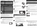
1
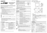
Guidelines for the Safety of the User and Protection of the F940WGOT Series. This manual has been written to be used by trained and competent personnel. The definition of such a person or persons is as follows: a) Any engineer using the product associated with this manual, should be of a competent nature, trained and qualified to the local and national standards. These engineers should be fully aware of all aspects of safety with regards to automated equipment. b) Any commissioning or service engineer must be of a competent nature, trained and qualified to the local and national standards. c) All operators of the completed equipment should be trained to use that product in a safe and co-ordinated manner in compliance to established safety practices. Note: The term ‘completed equipment’ refers to a third party constructed device which contains or uses the product associated with this manual. Note’s on the Symbols Used in this Manual At various times through out this manual certain symbols will be used to highlight points of information which are intended to ensure the users personal safety and protect the integrity of equipment. 1) Indicates that the identified danger WILL cause physical and property damage. 2) Indicates that the identified danger could POSSIBLY cause physical and property damage. • Operate touch switches on the display screen by hand. DO NOT use excessive force, or attempt operate them with hard or pointed objects. The tip of a screw driver, pen or similar object for example may break the screen. ~ Indispensable manual | Either manual is necessary. Refer if necessary, please. Refer to the Programming manual (ΙΙ) or relevant hardware manuals for details concerning the applicable PLC. 1.2 Dimensions and Each Part Name Dimensions: mm (inches) Accessory: 1. Introduction a ) The F940WGOT series (hereafter called “GOT”) is to be mounted on the face of a control panel or operations panel, and c o nn e ct e d t o t he pr o gra m m in g p or t ( CP U po r t ) o r t h e communication port (communication port) of a PLC. Various devices can be monitored and PLC data changed through the GOT screens. Several display screens are built-in to the GOT, and additional personalized screens can be created by the user. b ) P r o g r a m m in g p o rt 1) The GOT can connect to MELSEC FX, A, QnA and Q PLCs as well as a host of third party manufactured units. Further information can be found in GOT-F900 Series Hardware Manual. 5 (0 .2 0 ") G O T 2 1 5 (8 .4 6 ") 1 0 (0 .3 9 ") 2) PLC user programs can be downloaded, uploaded and monitored using programming software GXDeveloper or FX-PCS/WIN-E on a personal computer via the GOT. Further information can be found in GOT-F900 Series Operation Manual. 3) Display screens are created using the following software: Software Name Under no circumstances will Mitsubishi Electric be liable or responsible for any consequential damage that may arise as a result of the installation or use of this equipment. • All examples and diagrams shown in this manual are intended only as an aid to understanding the text, not to guarantee operation. Mitsubishi Electric will accept no responsibility for actual use of the product based on these illustrative examples. • Owing to the very great variety in possible application of this equipment, you must satisfy yourself as to its suitability for your specific application. Associated Manuals Manual Name F940WGOT Series | (F940GOT-TWD) Installation Manual Manual Number JY997D93901 Description Describes the specifications, wiring, and installation of F940WGOT Series graphic operation terminal. (hardware) f ) GOT-F900 and GOT-A900 Series (for Windows) screen creation software. SW5-F edition of SW5D5C-GOTR-PACKE (version 5.05F) or later FX-PCS-DU/WIN-E GOT-F900 Series (for Windows) screen creation software. SW0PC-FXDU/WIN-E version 2.50 or later Communication cable (GOT ↔ CPU port in FX0, FX0S, FX1S, FX0N, FX1N, FX2N or FX2NC series PLC) FX-50DU-CAB0-**M The connector on the GOT side is wired straight through. ** M is cable length. 1M: 1m (3' 3"), 10M: 10m (32' 9"), 20M: 20m (65' 7"), 30M: 30m (98' 5") GOT-F900 Series Operation Manual JY992D94701 (separate volume) GOT-F900 Series ~ Hardware Manual (connection diagram) JY992D94801 (separate volume) Describes wiring and installation of the GOTF900 Series graphic operation terminals. FX-40DU-CAB-**M Communication cable (GOT ↔ CPU port in FX, FX2C, A or QnA series PLC) The connector on the GOT side is wired straight through. ** M is cable length. 10M: 10m (32' 9"), 20M: 20m (65' 7"), 30M: 30m (98' 5") QC30R2 Communication cable (GOT ↔ CPU port in Q series PLC) The connector on the GOT side wired straight through. Cable length is 3m (9' 10"). FX-232CAB-1 Data exchange cable (GOT ↔ Personal computer <9-pin D-sub>) PM-20BL Battery for Alarm history, sampling and current time data retention. F9WGT-40PSC Transparent protection sheet for F940WGOT (5 pieces) F9GT-40FMB Data transfer adapter (Flash memory built in) Describes the operation of GT Designer2 (SW*D5C-GTD2-E) and data transfer to the GOT-900 Series. GT Designer2 Version1 Reference Manual (PDF files on CDROM included with product) Describes the specifications and setting of object functions in GT Designer2 (SW*D5C-GTD2-E). GT Designer Operating Manual Included with the screen creation software Describes the operation of GT Designer (SW*D5C-GOTR-PACKE) and data transfer to the GOT-900 Series. (Refer to the help file) | | | FX-PCS-DU/WIN-E SOFTWARE MANUAL JY992D68301 (included with the screen creation software) Describes the operation of FX-PCS-DU/WIN-E screen creation software. Communication cable (GOT ↔ CPU port in FX, FX2C, A or QnA series PLC) The connector on the GOT side is wired straight through. Cable length is 3m (9' 10"). Caution During abnormal communication (including cable breakages) ages when monitor within the GOT, communication between the GOT and programmable controller CPU is interrupted. It is impossible to operate switches or devices in the PLC through the GOT. Communication and normal operation resumes when the GOT system is correctly configured. DO NOT configure emergency stop or safety features to operate through the GOT, and be sure that there is no adverse consequences in the event of a GOT - PLC communications malfunction. 3 4 .5 (1 .3 5 ") 5 ( 0 .2 0 " ) o r le s s h ) b) Mounting bracket hole c) Communication ports Communication cable (GOT ↔ CPU port in FX0, FX0S, FX1S, FX0N, FX1N, FX2N or FX2NC series PLC) The connector on the GOT side is wired straight through. Cable length is 3m (9' 10"). FX-40DU-CAB (PDF files on CDROM included with product) e ) 2 3 (0 .9 1 ") 2 3 (0 .9 1 ") a) Display Description COM0 RS-422 port for connecting PLC (including1:N connection) or communication (computer link) unit <9-pin D-sub> COM1 RS-232C port for connecting PLC (including1:N connection), printer or bar-code reader <9-pin D-sub> COM2 RS-232C port for connecting personal computer, printer or bar-code reader <9-pin D-sub> F940WGOT-TWD-E Graphic operation terminal main unit Describes the operation and use of the GOTF900 Series graphic operation terminals, GT Designer and FX-PCS-DU/WIN-E. GT Designer2 Version1 | Operating Manual D C 2 0 5 (8 .0 7 ") Description Communication cable (GOT ↔ CPU port in FX0, FX0S, FX1S, FX0N, FX1N, FX2N or FX2NC series PLC) FX-50DU-CAB0/EN The connector on the GOT side is wired straight through. Cable length is 3m (9' 10"). 7 0 .6 (2 .7 8 ) c ) Port JY997D09101 (separate volume) ~ 2 4 V 3 4 .5 (1 .3 5 ") Describes the operation and use of the GOTF900 Series graphic operation terminals and GT Designer2. GOT-F900 ~ OPERATION MANUAL (describes GT Designer2) 1 0 (0 .3 9 ") 7 0 .6 (2 .7 8 ") g ) GOT-F900 and GOT-A900 Series (for Windows) screen creation software. GT Designer SW D5C-GOTR-PACKE ( indicates version) FX-50DU-CAB0 d ) Version GT Designer2 SW D5C-GTD2-E ( indicates version) Production Name c ) P L C 1.1 Product Lists • MASS (Weight): 1 kg (2.2 lbs) Mounting brackets, Tightening bolt (M3, 6 bolts), Packing seal for dust and water resistance 1 2 3 (4 .8 4 ") Specifications are subject to change without notice Do not lay signal cables near high voltage power cables or allow them to share the same trunking duct, otherwise, effects of noise or surge induction are likely to take please. Keep a safe distance of more than 100 mm from these wires. 1 3 3 (5 .2 4 ") This manual contains text, diagrams and explanations which will guide the reader in the correct installation, safe use and operation of the F940WGOT-TWD-E and should be read and understood before attempting to install or use the unit. Further information can be found in the associated manuals list below. • JY992D98601 1 4 3 (5 .6 3 ") JY992D93901E Note; 2 3 (0 .9 1 ") Installation Manual Description This manual contains explanations for installation and operating procedures of the F9GT-40FMB data transfer adapter. 5 0 (1 .9 6 ") F940WGOT Series (F940WGOT-TWD) F9GT-40FMB User’s Manual Manual Number 1 3 3 (5 .2 4 ") Manual Name d) Mounting bracket and tightening bolt f) DC power supply terminal (M3) h) Packing seal e) PM-20BL battery g) Communication cable 2. Specifications 2.1 General Specifications Item Operating Temperature Specifications Horizontal mounting: 0 ~ 50 °C (32 ~ 122 °F) Vertical and flat mounting: 0 ~ 40 °C (32 ~ 104 °F) Storage Temperature -20 ~ 60 °C (-4 ~ 140 °F) Humidity 35 ~ 85% Relative Humidity, No condensation Operating atmosphere Must be free of lamp black, corrosive gas, flammable gas, or excessive amount of electroconductive dust particles and must be no direct sunlight. (Same as for saving) Vibration Resistance - intermittent vibration 10 ~ 57 Hz: 0.075 mm Half Amplitude 57 ~ 150 Hz: 9.8 m/s2 Acceleration Sweep Count for X, Y, Z: 10 times (80 min. in each direction) Vibration Resistance - Continuous vibration 10 ~ 57 Hz: 0.035 mm Half Amplitude 57 ~ 150 Hz: 4.9 m/s2 Acceleration Sweep Count for X, Y, Z: 10 times (80 min in each direction) Shock Resistance 147m/s2 Acceleration, 3 times in each direction X, Y, and Z Noise Immunity 1000 Vp-p, 1micro second, 30 ~ 100 Hz, tested by noise simulator Dielectric Withstand Voltage 500 V AC > 1 min, tested between power terminals and ground Insulation Resistance 5 MΩ > at 500 V DC, tested between power terminals and ground Ground Grounding resistance 100 Ω or less. (Class D) Protection IP 65F Guidelines for the Safety of the User and Protection of the F940WGOT Series. This manual has been written to be used by trained and competent personnel. The definition of such a person or persons is as follows: a) Any engineer using the product associated with this manual, should be of a competent nature, trained and qualified to the local and national standards. These engineers should be fully aware of all aspects of safety with regards to automated equipment. b) Any commissioning or service engineer must be of a competent nature, trained and qualified to the local and national standards. c) All operators of the completed equipment should be trained to use that product in a safe and co-ordinated manner in compliance to established safety practices. Note: The term ‘completed equipment’ refers to a third party constructed device which contains or uses the product associated with this manual. Note’s on the Symbols Used in this Manual At various times through out this manual certain symbols will be used to highlight points of information which are intended to ensure the users personal safety and protect the integrity of equipment. 1) Indicates that the identified danger WILL cause physical and property damage. 2) Indicates that the identified danger could POSSIBLY cause physical and property damage. • Operate touch switches on the display screen by hand. DO NOT use excessive force, or attempt operate them with hard or pointed objects. The tip of a screw driver, pen or similar object for example may break the screen. ~ Indispensable manual | Either manual is necessary. Refer if necessary, please. Refer to the Programming manual (ΙΙ) or relevant hardware manuals for details concerning the applicable PLC. 1.2 Dimensions and Each Part Name Dimensions: mm (inches) Accessory: 1. Introduction a ) The F940WGOT series (hereafter called “GOT”) is to be mounted on the face of a control panel or operations panel, and c o nn e ct e d t o t he pr o gra m m in g p or t ( CP U po r t ) o r t h e communication port (communication port) of a PLC. Various devices can be monitored and PLC data changed through the GOT screens. Several display screens are built-in to the GOT, and additional personalized screens can be created by the user. b ) P r o g r a m m in g p o rt 1) The GOT can connect to MELSEC FX, A, QnA and Q PLCs as well as a host of third party manufactured units. Further information can be found in GOT-F900 Series Hardware Manual. 5 (0 .2 0 ") G O T 2 1 5 (8 .4 6 ") 1 0 (0 .3 9 ") 2) PLC user programs can be downloaded, uploaded and monitored using programming software GXDeveloper or FX-PCS/WIN-E on a personal computer via the GOT. Further information can be found in GOT-F900 Series Operation Manual. 3) Display screens are created using the following software: Software Name Under no circumstances will Mitsubishi Electric be liable or responsible for any consequential damage that may arise as a result of the installation or use of this equipment. • All examples and diagrams shown in this manual are intended only as an aid to understanding the text, not to guarantee operation. Mitsubishi Electric will accept no responsibility for actual use of the product based on these illustrative examples. • Owing to the very great variety in possible application of this equipment, you must satisfy yourself as to its suitability for your specific application. Associated Manuals Manual Name F940WGOT Series | (F940GOT-TWD) Installation Manual Manual Number JY997D93901 Description Describes the specifications, wiring, and installation of F940WGOT Series graphic operation terminal. (hardware) f ) GOT-F900 and GOT-A900 Series (for Windows) screen creation software. SW5-F edition of SW5D5C-GOTR-PACKE (version 5.05F) or later FX-PCS-DU/WIN-E GOT-F900 Series (for Windows) screen creation software. SW0PC-FXDU/WIN-E version 2.50 or later Communication cable (GOT ↔ CPU port in FX0, FX0S, FX1S, FX0N, FX1N, FX2N or FX2NC series PLC) FX-50DU-CAB0-**M The connector on the GOT side is wired straight through. ** M is cable length. 1M: 1m (3' 3"), 10M: 10m (32' 9"), 20M: 20m (65' 7"), 30M: 30m (98' 5") GOT-F900 Series Operation Manual JY992D94701 (separate volume) GOT-F900 Series ~ Hardware Manual (connection diagram) JY992D94801 (separate volume) Describes wiring and installation of the GOTF900 Series graphic operation terminals. FX-40DU-CAB-**M Communication cable (GOT ↔ CPU port in FX, FX2C, A or QnA series PLC) The connector on the GOT side is wired straight through. ** M is cable length. 10M: 10m (32' 9"), 20M: 20m (65' 7"), 30M: 30m (98' 5") QC30R2 Communication cable (GOT ↔ CPU port in Q series PLC) The connector on the GOT side wired straight through. Cable length is 3m (9' 10"). FX-232CAB-1 Data exchange cable (GOT ↔ Personal computer <9-pin D-sub>) PM-20BL Battery for Alarm history, sampling and current time data retention. F9WGT-40PSC Transparent protection sheet for F940WGOT (5 pieces) F9GT-40FMB Data transfer adapter (Flash memory built in) Describes the operation of GT Designer2 (SW*D5C-GTD2-E) and data transfer to the GOT-900 Series. GT Designer2 Version1 Reference Manual (PDF files on CDROM included with product) Describes the specifications and setting of object functions in GT Designer2 (SW*D5C-GTD2-E). GT Designer Operating Manual Included with the screen creation software Describes the operation of GT Designer (SW*D5C-GOTR-PACKE) and data transfer to the GOT-900 Series. (Refer to the help file) | | | FX-PCS-DU/WIN-E SOFTWARE MANUAL JY992D68301 (included with the screen creation software) Describes the operation of FX-PCS-DU/WIN-E screen creation software. Communication cable (GOT ↔ CPU port in FX, FX2C, A or QnA series PLC) The connector on the GOT side is wired straight through. Cable length is 3m (9' 10"). Caution During abnormal communication (including cable breakages) ages when monitor within the GOT, communication between the GOT and programmable controller CPU is interrupted. It is impossible to operate switches or devices in the PLC through the GOT. Communication and normal operation resumes when the GOT system is correctly configured. DO NOT configure emergency stop or safety features to operate through the GOT, and be sure that there is no adverse consequences in the event of a GOT - PLC communications malfunction. 3 4 .5 (1 .3 5 ") 5 ( 0 .2 0 " ) o r le s s h ) b) Mounting bracket hole c) Communication ports Communication cable (GOT ↔ CPU port in FX0, FX0S, FX1S, FX0N, FX1N, FX2N or FX2NC series PLC) The connector on the GOT side is wired straight through. Cable length is 3m (9' 10"). FX-40DU-CAB (PDF files on CDROM included with product) e ) 2 3 (0 .9 1 ") 2 3 (0 .9 1 ") a) Display Description COM0 RS-422 port for connecting PLC (including1:N connection) or communication (computer link) unit <9-pin D-sub> COM1 RS-232C port for connecting PLC (including1:N connection), printer or bar-code reader <9-pin D-sub> COM2 RS-232C port for connecting personal computer, printer or bar-code reader <9-pin D-sub> F940WGOT-TWD-E Graphic operation terminal main unit Describes the operation and use of the GOTF900 Series graphic operation terminals, GT Designer and FX-PCS-DU/WIN-E. GT Designer2 Version1 | Operating Manual D C 2 0 5 (8 .0 7 ") Description Communication cable (GOT ↔ CPU port in FX0, FX0S, FX1S, FX0N, FX1N, FX2N or FX2NC series PLC) FX-50DU-CAB0/EN The connector on the GOT side is wired straight through. Cable length is 3m (9' 10"). 7 0 .6 (2 .7 8 ) c ) Port JY997D09101 (separate volume) ~ 2 4 V 3 4 .5 (1 .3 5 ") Describes the operation and use of the GOTF900 Series graphic operation terminals and GT Designer2. GOT-F900 ~ OPERATION MANUAL (describes GT Designer2) 1 0 (0 .3 9 ") 7 0 .6 (2 .7 8 ") g ) GOT-F900 and GOT-A900 Series (for Windows) screen creation software. GT Designer SW D5C-GOTR-PACKE ( indicates version) FX-50DU-CAB0 d ) Version GT Designer2 SW D5C-GTD2-E ( indicates version) Production Name c ) P L C 1.1 Product Lists • MASS (Weight): 1 kg (2.2 lbs) Mounting brackets, Tightening bolt (M3, 6 bolts), Packing seal for dust and water resistance 1 2 3 (4 .8 4 ") Specifications are subject to change without notice Do not lay signal cables near high voltage power cables or allow them to share the same trunking duct, otherwise, effects of noise or surge induction are likely to take please. Keep a safe distance of more than 100 mm from these wires. 1 3 3 (5 .2 4 ") This manual contains text, diagrams and explanations which will guide the reader in the correct installation, safe use and operation of the F940WGOT-TWD-E and should be read and understood before attempting to install or use the unit. Further information can be found in the associated manuals list below. • JY992D98601 1 4 3 (5 .6 3 ") JY992D93901E Note; 2 3 (0 .9 1 ") Installation Manual Description This manual contains explanations for installation and operating procedures of the F9GT-40FMB data transfer adapter. 5 0 (1 .9 6 ") F940WGOT Series (F940WGOT-TWD) F9GT-40FMB User’s Manual Manual Number 1 3 3 (5 .2 4 ") Manual Name d) Mounting bracket and tightening bolt f) DC power supply terminal (M3) h) Packing seal e) PM-20BL battery g) Communication cable 2. Specifications 2.1 General Specifications Item Operating Temperature Specifications Horizontal mounting: 0 ~ 50 °C (32 ~ 122 °F) Vertical and flat mounting: 0 ~ 40 °C (32 ~ 104 °F) Storage Temperature -20 ~ 60 °C (-4 ~ 140 °F) Humidity 35 ~ 85% Relative Humidity, No condensation Operating atmosphere Must be free of lamp black, corrosive gas, flammable gas, or excessive amount of electroconductive dust particles and must be no direct sunlight. (Same as for saving) Vibration Resistance - intermittent vibration 10 ~ 57 Hz: 0.075 mm Half Amplitude 57 ~ 150 Hz: 9.8 m/s2 Acceleration Sweep Count for X, Y, Z: 10 times (80 min. in each direction) Vibration Resistance - Continuous vibration 10 ~ 57 Hz: 0.035 mm Half Amplitude 57 ~ 150 Hz: 4.9 m/s2 Acceleration Sweep Count for X, Y, Z: 10 times (80 min in each direction) Shock Resistance 147m/s2 Acceleration, 3 times in each direction X, Y, and Z Noise Immunity 1000 Vp-p, 1micro second, 30 ~ 100 Hz, tested by noise simulator Dielectric Withstand Voltage 500 V AC > 1 min, tested between power terminals and ground Insulation Resistance 5 MΩ > at 500 V DC, tested between power terminals and ground Ground Grounding resistance 100 Ω or less. (Class D) Protection IP 65F Guidelines for the Safety of the User and Protection of the F940WGOT Series. This manual has been written to be used by trained and competent personnel. The definition of such a person or persons is as follows: a) Any engineer using the product associated with this manual, should be of a competent nature, trained and qualified to the local and national standards. These engineers should be fully aware of all aspects of safety with regards to automated equipment. b) Any commissioning or service engineer must be of a competent nature, trained and qualified to the local and national standards. c) All operators of the completed equipment should be trained to use that product in a safe and co-ordinated manner in compliance to established safety practices. Note: The term ‘completed equipment’ refers to a third party constructed device which contains or uses the product associated with this manual. Note’s on the Symbols Used in this Manual At various times through out this manual certain symbols will be used to highlight points of information which are intended to ensure the users personal safety and protect the integrity of equipment. 1) Indicates that the identified danger WILL cause physical and property damage. 2) Indicates that the identified danger could POSSIBLY cause physical and property damage. • Operate touch switches on the display screen by hand. DO NOT use excessive force, or attempt operate them with hard or pointed objects. The tip of a screw driver, pen or similar object for example may break the screen. ~ Indispensable manual | Either manual is necessary. Refer if necessary, please. Refer to the Programming manual (ΙΙ) or relevant hardware manuals for details concerning the applicable PLC. 1.2 Dimensions and Each Part Name Dimensions: mm (inches) Accessory: 1. Introduction a ) The F940WGOT series (hereafter called “GOT”) is to be mounted on the face of a control panel or operations panel, and c o nn e ct e d t o t he pr o gra m m in g p or t ( CP U po r t ) o r t h e communication port (communication port) of a PLC. Various devices can be monitored and PLC data changed through the GOT screens. Several display screens are built-in to the GOT, and additional personalized screens can be created by the user. b ) P r o g r a m m in g p o rt 1) The GOT can connect to MELSEC FX, A, QnA and Q PLCs as well as a host of third party manufactured units. Further information can be found in GOT-F900 Series Hardware Manual. 5 (0 .2 0 ") G O T 2 1 5 (8 .4 6 ") 1 0 (0 .3 9 ") 2) PLC user programs can be downloaded, uploaded and monitored using programming software GXDeveloper or FX-PCS/WIN-E on a personal computer via the GOT. Further information can be found in GOT-F900 Series Operation Manual. 3) Display screens are created using the following software: Software Name Under no circumstances will Mitsubishi Electric be liable or responsible for any consequential damage that may arise as a result of the installation or use of this equipment. • All examples and diagrams shown in this manual are intended only as an aid to understanding the text, not to guarantee operation. Mitsubishi Electric will accept no responsibility for actual use of the product based on these illustrative examples. • Owing to the very great variety in possible application of this equipment, you must satisfy yourself as to its suitability for your specific application. Associated Manuals Manual Name F940WGOT Series | (F940GOT-TWD) Installation Manual Manual Number JY997D93901 Description Describes the specifications, wiring, and installation of F940WGOT Series graphic operation terminal. (hardware) f ) GOT-F900 and GOT-A900 Series (for Windows) screen creation software. SW5-F edition of SW5D5C-GOTR-PACKE (version 5.05F) or later FX-PCS-DU/WIN-E GOT-F900 Series (for Windows) screen creation software. SW0PC-FXDU/WIN-E version 2.50 or later Communication cable (GOT ↔ CPU port in FX0, FX0S, FX1S, FX0N, FX1N, FX2N or FX2NC series PLC) FX-50DU-CAB0-**M The connector on the GOT side is wired straight through. ** M is cable length. 1M: 1m (3' 3"), 10M: 10m (32' 9"), 20M: 20m (65' 7"), 30M: 30m (98' 5") GOT-F900 Series Operation Manual JY992D94701 (separate volume) GOT-F900 Series ~ Hardware Manual (connection diagram) JY992D94801 (separate volume) Describes wiring and installation of the GOTF900 Series graphic operation terminals. FX-40DU-CAB-**M Communication cable (GOT ↔ CPU port in FX, FX2C, A or QnA series PLC) The connector on the GOT side is wired straight through. ** M is cable length. 10M: 10m (32' 9"), 20M: 20m (65' 7"), 30M: 30m (98' 5") QC30R2 Communication cable (GOT ↔ CPU port in Q series PLC) The connector on the GOT side wired straight through. Cable length is 3m (9' 10"). FX-232CAB-1 Data exchange cable (GOT ↔ Personal computer <9-pin D-sub>) PM-20BL Battery for Alarm history, sampling and current time data retention. F9WGT-40PSC Transparent protection sheet for F940WGOT (5 pieces) F9GT-40FMB Data transfer adapter (Flash memory built in) Describes the operation of GT Designer2 (SW*D5C-GTD2-E) and data transfer to the GOT-900 Series. GT Designer2 Version1 Reference Manual (PDF files on CDROM included with product) Describes the specifications and setting of object functions in GT Designer2 (SW*D5C-GTD2-E). GT Designer Operating Manual Included with the screen creation software Describes the operation of GT Designer (SW*D5C-GOTR-PACKE) and data transfer to the GOT-900 Series. (Refer to the help file) | | | FX-PCS-DU/WIN-E SOFTWARE MANUAL JY992D68301 (included with the screen creation software) Describes the operation of FX-PCS-DU/WIN-E screen creation software. Communication cable (GOT ↔ CPU port in FX, FX2C, A or QnA series PLC) The connector on the GOT side is wired straight through. Cable length is 3m (9' 10"). Caution During abnormal communication (including cable breakages) ages when monitor within the GOT, communication between the GOT and programmable controller CPU is interrupted. It is impossible to operate switches or devices in the PLC through the GOT. Communication and normal operation resumes when the GOT system is correctly configured. DO NOT configure emergency stop or safety features to operate through the GOT, and be sure that there is no adverse consequences in the event of a GOT - PLC communications malfunction. 3 4 .5 (1 .3 5 ") 5 ( 0 .2 0 " ) o r le s s h ) b) Mounting bracket hole c) Communication ports Communication cable (GOT ↔ CPU port in FX0, FX0S, FX1S, FX0N, FX1N, FX2N or FX2NC series PLC) The connector on the GOT side is wired straight through. Cable length is 3m (9' 10"). FX-40DU-CAB (PDF files on CDROM included with product) e ) 2 3 (0 .9 1 ") 2 3 (0 .9 1 ") a) Display Description COM0 RS-422 port for connecting PLC (including1:N connection) or communication (computer link) unit <9-pin D-sub> COM1 RS-232C port for connecting PLC (including1:N connection), printer or bar-code reader <9-pin D-sub> COM2 RS-232C port for connecting personal computer, printer or bar-code reader <9-pin D-sub> F940WGOT-TWD-E Graphic operation terminal main unit Describes the operation and use of the GOTF900 Series graphic operation terminals, GT Designer and FX-PCS-DU/WIN-E. GT Designer2 Version1 | Operating Manual D C 2 0 5 (8 .0 7 ") Description Communication cable (GOT ↔ CPU port in FX0, FX0S, FX1S, FX0N, FX1N, FX2N or FX2NC series PLC) FX-50DU-CAB0/EN The connector on the GOT side is wired straight through. Cable length is 3m (9' 10"). 7 0 .6 (2 .7 8 ) c ) Port JY997D09101 (separate volume) ~ 2 4 V 3 4 .5 (1 .3 5 ") Describes the operation and use of the GOTF900 Series graphic operation terminals and GT Designer2. GOT-F900 ~ OPERATION MANUAL (describes GT Designer2) 1 0 (0 .3 9 ") 7 0 .6 (2 .7 8 ") g ) GOT-F900 and GOT-A900 Series (for Windows) screen creation software. GT Designer SW D5C-GOTR-PACKE ( indicates version) FX-50DU-CAB0 d ) Version GT Designer2 SW D5C-GTD2-E ( indicates version) Production Name c ) P L C 1.1 Product Lists • MASS (Weight): 1 kg (2.2 lbs) Mounting brackets, Tightening bolt (M3, 6 bolts), Packing seal for dust and water resistance 1 2 3 (4 .8 4 ") Specifications are subject to change without notice Do not lay signal cables near high voltage power cables or allow them to share the same trunking duct, otherwise, effects of noise or surge induction are likely to take please. Keep a safe distance of more than 100 mm from these wires. 1 3 3 (5 .2 4 ") This manual contains text, diagrams and explanations which will guide the reader in the correct installation, safe use and operation of the F940WGOT-TWD-E and should be read and understood before attempting to install or use the unit. Further information can be found in the associated manuals list below. • JY992D98601 1 4 3 (5 .6 3 ") JY992D93901E Note; 2 3 (0 .9 1 ") Installation Manual Description This manual contains explanations for installation and operating procedures of the F9GT-40FMB data transfer adapter. 5 0 (1 .9 6 ") F940WGOT Series (F940WGOT-TWD) F9GT-40FMB User’s Manual Manual Number 1 3 3 (5 .2 4 ") Manual Name d) Mounting bracket and tightening bolt f) DC power supply terminal (M3) h) Packing seal e) PM-20BL battery g) Communication cable 2. Specifications 2.1 General Specifications Item Operating Temperature Specifications Horizontal mounting: 0 ~ 50 °C (32 ~ 122 °F) Vertical and flat mounting: 0 ~ 40 °C (32 ~ 104 °F) Storage Temperature -20 ~ 60 °C (-4 ~ 140 °F) Humidity 35 ~ 85% Relative Humidity, No condensation Operating atmosphere Must be free of lamp black, corrosive gas, flammable gas, or excessive amount of electroconductive dust particles and must be no direct sunlight. (Same as for saving) Vibration Resistance - intermittent vibration 10 ~ 57 Hz: 0.075 mm Half Amplitude 57 ~ 150 Hz: 9.8 m/s2 Acceleration Sweep Count for X, Y, Z: 10 times (80 min. in each direction) Vibration Resistance - Continuous vibration 10 ~ 57 Hz: 0.035 mm Half Amplitude 57 ~ 150 Hz: 4.9 m/s2 Acceleration Sweep Count for X, Y, Z: 10 times (80 min in each direction) Shock Resistance 147m/s2 Acceleration, 3 times in each direction X, Y, and Z Noise Immunity 1000 Vp-p, 1micro second, 30 ~ 100 Hz, tested by noise simulator Dielectric Withstand Voltage 500 V AC > 1 min, tested between power terminals and ground Insulation Resistance 5 MΩ > at 500 V DC, tested between power terminals and ground Ground Grounding resistance 100 Ω or less. (Class D) Protection IP 65F 2.2 Power Supply Specifications • Specifications Power Supply Voltage 24V DC, +10% -15% Power Supply Ripple 200 mV or less Current Consumption Ratings: 650 mA at 24V DC 750 mA at 24V DC or less when power supply is turned ON 400 mA at 24 V DC when backlight is turned OFF 2) Inserting the GOT into the panel surface Attach the packing seal to the GOT, and insert the GOT from the front face of the panel surface. Fuse built-in GOT (impossible to change) 1 ms; If less than 1 ms, the GOT will continue operation. If 1 ms or more, the GOT will shut down. Battery Built-in, PM-20BL type lithium battery. (Approximately 5 years life) TFT colour liquid crystal Resolution 480 × 234 (dot), 60 characters × 14 lines Dot Pitch 0.324 mm (0.013") Horizontal × 0.375 mm (0.015") Vertical. [Actual character size ratio 1:1.16] Effective Display Size 155.5 mm (6.12") × 87.8 mm (3.46"); 7 (inch) type Number of Colours 256 colours Life of liquid crystal 50,000 hours or more (Operating temperature: 25 °C / 77°F) Backlight Cold cathode tube Life of Backlight 50,000 hours or more (Operating temperature: 25 °C / 77°F) Touch Keys Maximum 50 touch keys / screen, 30 × 12 matrix COM1 RS-232C COM2 • • • a ) b) Mounting bracket b ) Correctly connect the battery for memory backup. Never charge, disassemble, heat, burn or short-circuit the battery. If the battery is handled in such a way, or fire may be caused. • Always power OFF and remove the GOT from the panel before starting replacement of the battery. If this is not the case, electrical shock may be sustained. • Never disassemble or modify the GOT. Disassembly or modification may cause failure, malfunction or fire. For repair, please, contact a service representative. Turn off the power, before connecting/disconnecting cables. Connecting/disconnecting cables while the power is turned on will cause failure or malfunction. When repairing the backlight and liquid crystal screen, please, contact a service representative. 6.1 Battery Replacement Note: Make sure to tighten the clamping bolts with a torque of 0.3 ~ 0.5 Nm. 4) Dimensions required inside the panel for installation. When installing the GOT, make sure that the inner dimensions shown on the right are available. RS-232C a) PLC connection cable Number of Screens b) Packing seal User Memory Flash memory 1MB (built-in) When the battery voltage drops, a control device (system information) set by the screen design software turns ON. The control device interlocks with an auxiliary relay in the PLC. It is recommended to provide a lamp while utilizing the output of the PLC so that voltage drop can be monitored outside the GOT. For details of control devices, refer to the GOT-F900 Series Operation Manual. 2 2 5 (8 .8 6 ") Note: 7 0 .6 (2 .7 8 ") For approximately one month after the control device (system information) for battery voltage drop turns ON, the battery will back up the alarm history, sampling and the current time. When the control device turns ON, replace the battery (PM-20BL) as soon as possible. The screen data is stored in the flash memory, therefore, data will remain even after severe battery voltage loss. 6.1.1 Replacement Procedure a ) Bright dots (always lit) and dark dots (unlit) may appear on a liquid crystal display panel. It is impossible to completely avoid this symptom, as the liquid crystal display comprises of a great number of display elements. Flickers may be observed depending on the display color. Please note that these dots appear due to its characteristic and are not caused by product defect. When the same screen is displayed for a long time, an incidental color or partial discoloration is generated on the screen due to heat damage, and it may not disappear. Using the GOT Backlight OFF function can prolong the life of the backlight. For details on the Backlight OFF function, refer to the following. GOT-F900 Series OPERATION MANUAL/GOT-F900 Series OPERATION MANUAL [GT Designer2 Version] 3. Installation 5 ( 0 .2 0 " ) o r le s s Do not mount the GOT in an environment that contains dust, soot corrosive or conducive dust, corrosive or flammable gas, or expose the unit to high temperatures, dew condensation, direct sunlight, rain wind or impact and vibration. If the GOT is used in such a place, electrical shock, fire, malfunction, damages or deterioration may caused. • Never drop cutting chips or electric wire chips into the ventilation window of the GOT when drilling screw holes or performing wiring. Such chips may cause fire, failure or malfunction. • Turn off the power before securely connecting any cables. Poor connection may cause malfunction. The GOT is designed to be mounted in a panel. Install it using the following procedure: 2 0 6 ( 8 .1 1 " ) + 1 (+ 0 .0 4 ") 0 S lo t to b e c u t o n p a n e l 1 2 4 ( 4 .8 8 " ) + 1 (+ 0 .0 4 ") U n it: m m ( in c h e s ) 1) Turn off the power to the GOT and remove the battery holder cover. b ) 2) Remove the existing battery from the battery holder, and disconnect. 3) Within 30 seconds, connect a new battery. 4. Power Supply Wiring 4) Insert the new battery into the battery holder, and attach the cover. Caution: Cut OFF all external phases of power source, before installation or wiring to avoid electric shock or serious damage to the product. P M -2 0 B L Note: • Wire the power supply using electric wires of 0.75 mm2 or more so that voltage drop will not occur. Use M3 size crimp style terminals. Securely tighten crimp-style terminals with a torque of 0.5 ~ 0.8 Nm so that errors can be avoided. • Insure correct termination of the DC power source, incorrect connection may result in unit failure serious damage to the GOT. • Attach a 2 A fuse to the 24V DC power supply. • Perform Class D (100Ω or less) grounding with an electric wire of at least 1.25 mm2. Never perform common grounding of the GOT and a strong power system. Note; 1) Preparing the panel surface. On the panel surface, cut a rectangular mounting slot of the dimensions shown on the right. At this time, space of 10 mm is required at each of the top and the bottom of the slot, inside the panel for metal fixtures as shown in “4) Dimensions required inside the panel for installation”. • Note: a) Clamping bolt User screen: 500 screens or less System screen: Allocated screens No. 1001-1030. • Cautions: c) Mounting slot 3) Fixing the GOT Put hooks of the mounting brackets (supplied) in to the mounting holes of the GOT. Tighten mounting bolts (also supplied) until the GOT is securely fixed. Fix mounting bolts in all four positions, above and below the GOT. Specifications Display Device Interface 6. Maintenance c ) 2.3 Screen Hardware Specifications RS-422 b ) b) GOT Max. Allowable Momentary Power Supply Failure period COM0 a ) F9GT-40FMB has a built-in flash memory and can transfer screen data when installed in the GOT. (When installed in the OS earlier than version 1.40, screen display is not available while transferring data from F9GT-40FMB to the GOT.) For the use methods and specifications, refer to the manual for F9GT-40FMB. a) Packing seal Fuse Items 5. Expansion Module (F9GT-40FMB) Make sure that the thickness of the panel surface is no more than 5 mm (0.20"). 1 4 3 (5 .6 3 ") Items Note Note • Use an external power supply to provide 24V DC. (The service power supply of the programmable controller cannot be used.) • Even if instantaneous power interruption of less than 1 ms occurs, the GOT continues to operate. When power interruption for a considerable period of time or voltage drop occurs, the GOT stops its operation. However, when the power supply is recovered, the GOT automatically restar ts its operation. (The screen displayed just after recovery is determined by the working environment originally set.) Grounding resistance 100Ω or less (class D) 24V DC external power supply Warranty Mitsubishi will not be held liable for damage caused by factors found not to be the cause of Mitsubishi; opportunity loss or lost profits caused by faults in the Mitsubishi products; damage, secondary damage, accident compensation caused by special factors unpredictable by Mitsubishi; damages to products other than Mitsubishi products; and to other duties. For the detailed warranty, refer to the GOT-F900 Series HARDWARE MANUAL [CONNECTION]. Manual number : JY992D93901 Manual revision : E Date : Sep. 2008 Fuse (2A) 0 24V DC PLC GOT HEAD OFFICE : TOKYO BUILDING, 2-7-3 MARUNOUCHI, CHIYODA-KU, TOKYO 100-8310, JAPAN HIMEJI WORKS : 840, CHIYODA CHO, HIMEJI, JAPAN 2.2 Power Supply Specifications • Specifications Power Supply Voltage 24V DC, +10% -15% Power Supply Ripple 200 mV or less Current Consumption Ratings: 650 mA at 24V DC 750 mA at 24V DC or less when power supply is turned ON 400 mA at 24 V DC when backlight is turned OFF 2) Inserting the GOT into the panel surface Attach the packing seal to the GOT, and insert the GOT from the front face of the panel surface. Fuse built-in GOT (impossible to change) 1 ms; If less than 1 ms, the GOT will continue operation. If 1 ms or more, the GOT will shut down. Battery Built-in, PM-20BL type lithium battery. (Approximately 5 years life) TFT colour liquid crystal Resolution 480 × 234 (dot), 60 characters × 14 lines Dot Pitch 0.324 mm (0.013") Horizontal × 0.375 mm (0.015") Vertical. [Actual character size ratio 1:1.16] Effective Display Size 155.5 mm (6.12") × 87.8 mm (3.46"); 7 (inch) type Number of Colours 256 colours Life of liquid crystal 50,000 hours or more (Operating temperature: 25 °C / 77°F) Backlight Cold cathode tube Life of Backlight 50,000 hours or more (Operating temperature: 25 °C / 77°F) Touch Keys Maximum 50 touch keys / screen, 30 × 12 matrix COM1 RS-232C COM2 • • • a ) b) Mounting bracket b ) Correctly connect the battery for memory backup. Never charge, disassemble, heat, burn or short-circuit the battery. If the battery is handled in such a way, or fire may be caused. • Always power OFF and remove the GOT from the panel before starting replacement of the battery. If this is not the case, electrical shock may be sustained. • Never disassemble or modify the GOT. Disassembly or modification may cause failure, malfunction or fire. For repair, please, contact a service representative. Turn off the power, before connecting/disconnecting cables. Connecting/disconnecting cables while the power is turned on will cause failure or malfunction. When repairing the backlight and liquid crystal screen, please, contact a service representative. 6.1 Battery Replacement Note: Make sure to tighten the clamping bolts with a torque of 0.3 ~ 0.5 Nm. 4) Dimensions required inside the panel for installation. When installing the GOT, make sure that the inner dimensions shown on the right are available. RS-232C a) PLC connection cable Number of Screens b) Packing seal User Memory Flash memory 1MB (built-in) When the battery voltage drops, a control device (system information) set by the screen design software turns ON. The control device interlocks with an auxiliary relay in the PLC. It is recommended to provide a lamp while utilizing the output of the PLC so that voltage drop can be monitored outside the GOT. For details of control devices, refer to the GOT-F900 Series Operation Manual. 2 2 5 (8 .8 6 ") Note: 7 0 .6 (2 .7 8 ") For approximately one month after the control device (system information) for battery voltage drop turns ON, the battery will back up the alarm history, sampling and the current time. When the control device turns ON, replace the battery (PM-20BL) as soon as possible. The screen data is stored in the flash memory, therefore, data will remain even after severe battery voltage loss. 6.1.1 Replacement Procedure a ) Bright dots (always lit) and dark dots (unlit) may appear on a liquid crystal display panel. It is impossible to completely avoid this symptom, as the liquid crystal display comprises of a great number of display elements. Flickers may be observed depending on the display color. Please note that these dots appear due to its characteristic and are not caused by product defect. When the same screen is displayed for a long time, an incidental color or partial discoloration is generated on the screen due to heat damage, and it may not disappear. Using the GOT Backlight OFF function can prolong the life of the backlight. For details on the Backlight OFF function, refer to the following. GOT-F900 Series OPERATION MANUAL/GOT-F900 Series OPERATION MANUAL [GT Designer2 Version] 3. Installation 5 ( 0 .2 0 " ) o r le s s Do not mount the GOT in an environment that contains dust, soot corrosive or conducive dust, corrosive or flammable gas, or expose the unit to high temperatures, dew condensation, direct sunlight, rain wind or impact and vibration. If the GOT is used in such a place, electrical shock, fire, malfunction, damages or deterioration may caused. • Never drop cutting chips or electric wire chips into the ventilation window of the GOT when drilling screw holes or performing wiring. Such chips may cause fire, failure or malfunction. • Turn off the power before securely connecting any cables. Poor connection may cause malfunction. The GOT is designed to be mounted in a panel. Install it using the following procedure: 2 0 6 ( 8 .1 1 " ) + 1 (+ 0 .0 4 ") 0 S lo t to b e c u t o n p a n e l 1 2 4 ( 4 .8 8 " ) + 1 (+ 0 .0 4 ") U n it: m m ( in c h e s ) 1) Turn off the power to the GOT and remove the battery holder cover. b ) 2) Remove the existing battery from the battery holder, and disconnect. 3) Within 30 seconds, connect a new battery. 4. Power Supply Wiring 4) Insert the new battery into the battery holder, and attach the cover. Caution: Cut OFF all external phases of power source, before installation or wiring to avoid electric shock or serious damage to the product. P M -2 0 B L Note: • Wire the power supply using electric wires of 0.75 mm2 or more so that voltage drop will not occur. Use M3 size crimp style terminals. Securely tighten crimp-style terminals with a torque of 0.5 ~ 0.8 Nm so that errors can be avoided. • Insure correct termination of the DC power source, incorrect connection may result in unit failure serious damage to the GOT. • Attach a 2 A fuse to the 24V DC power supply. • Perform Class D (100Ω or less) grounding with an electric wire of at least 1.25 mm2. Never perform common grounding of the GOT and a strong power system. Note; 1) Preparing the panel surface. On the panel surface, cut a rectangular mounting slot of the dimensions shown on the right. At this time, space of 10 mm is required at each of the top and the bottom of the slot, inside the panel for metal fixtures as shown in “4) Dimensions required inside the panel for installation”. • Note: a) Clamping bolt User screen: 500 screens or less System screen: Allocated screens No. 1001-1030. • Cautions: c) Mounting slot 3) Fixing the GOT Put hooks of the mounting brackets (supplied) in to the mounting holes of the GOT. Tighten mounting bolts (also supplied) until the GOT is securely fixed. Fix mounting bolts in all four positions, above and below the GOT. Specifications Display Device Interface 6. Maintenance c ) 2.3 Screen Hardware Specifications RS-422 b ) b) GOT Max. Allowable Momentary Power Supply Failure period COM0 a ) F9GT-40FMB has a built-in flash memory and can transfer screen data when installed in the GOT. (When installed in the OS earlier than version 1.40, screen display is not available while transferring data from F9GT-40FMB to the GOT.) For the use methods and specifications, refer to the manual for F9GT-40FMB. a) Packing seal Fuse Items 5. Expansion Module (F9GT-40FMB) Make sure that the thickness of the panel surface is no more than 5 mm (0.20"). 1 4 3 (5 .6 3 ") Items Note Note • Use an external power supply to provide 24V DC. (The service power supply of the programmable controller cannot be used.) • Even if instantaneous power interruption of less than 1 ms occurs, the GOT continues to operate. When power interruption for a considerable period of time or voltage drop occurs, the GOT stops its operation. However, when the power supply is recovered, the GOT automatically restar ts its operation. (The screen displayed just after recovery is determined by the working environment originally set.) Grounding resistance 100Ω or less (class D) 24V DC external power supply Warranty Mitsubishi will not be held liable for damage caused by factors found not to be the cause of Mitsubishi; opportunity loss or lost profits caused by faults in the Mitsubishi products; damage, secondary damage, accident compensation caused by special factors unpredictable by Mitsubishi; damages to products other than Mitsubishi products; and to other duties. For the detailed warranty, refer to the GOT-F900 Series HARDWARE MANUAL [CONNECTION]. Manual number : JY992D93901 Manual revision : E Date : Sep. 2008 Fuse (2A) 0 24V DC PLC GOT HEAD OFFICE : TOKYO BUILDING, 2-7-3 MARUNOUCHI, CHIYODA-KU, TOKYO 100-8310, JAPAN HIMEJI WORKS : 840, CHIYODA CHO, HIMEJI, JAPAN 2.2 Power Supply Specifications • Specifications Power Supply Voltage 24V DC, +10% -15% Power Supply Ripple 200 mV or less Current Consumption Ratings: 650 mA at 24V DC 750 mA at 24V DC or less when power supply is turned ON 400 mA at 24 V DC when backlight is turned OFF 2) Inserting the GOT into the panel surface Attach the packing seal to the GOT, and insert the GOT from the front face of the panel surface. Fuse built-in GOT (impossible to change) 1 ms; If less than 1 ms, the GOT will continue operation. If 1 ms or more, the GOT will shut down. Battery Built-in, PM-20BL type lithium battery. (Approximately 5 years life) TFT colour liquid crystal Resolution 480 × 234 (dot), 60 characters × 14 lines Dot Pitch 0.324 mm (0.013") Horizontal × 0.375 mm (0.015") Vertical. [Actual character size ratio 1:1.16] Effective Display Size 155.5 mm (6.12") × 87.8 mm (3.46"); 7 (inch) type Number of Colours 256 colours Life of liquid crystal 50,000 hours or more (Operating temperature: 25 °C / 77°F) Backlight Cold cathode tube Life of Backlight 50,000 hours or more (Operating temperature: 25 °C / 77°F) Touch Keys Maximum 50 touch keys / screen, 30 × 12 matrix COM1 RS-232C COM2 • • • a ) b) Mounting bracket b ) Correctly connect the battery for memory backup. Never charge, disassemble, heat, burn or short-circuit the battery. If the battery is handled in such a way, or fire may be caused. • Always power OFF and remove the GOT from the panel before starting replacement of the battery. If this is not the case, electrical shock may be sustained. • Never disassemble or modify the GOT. Disassembly or modification may cause failure, malfunction or fire. For repair, please, contact a service representative. Turn off the power, before connecting/disconnecting cables. Connecting/disconnecting cables while the power is turned on will cause failure or malfunction. When repairing the backlight and liquid crystal screen, please, contact a service representative. 6.1 Battery Replacement Note: Make sure to tighten the clamping bolts with a torque of 0.3 ~ 0.5 Nm. 4) Dimensions required inside the panel for installation. When installing the GOT, make sure that the inner dimensions shown on the right are available. RS-232C a) PLC connection cable Number of Screens b) Packing seal User Memory Flash memory 1MB (built-in) When the battery voltage drops, a control device (system information) set by the screen design software turns ON. The control device interlocks with an auxiliary relay in the PLC. It is recommended to provide a lamp while utilizing the output of the PLC so that voltage drop can be monitored outside the GOT. For details of control devices, refer to the GOT-F900 Series Operation Manual. 2 2 5 (8 .8 6 ") Note: 7 0 .6 (2 .7 8 ") For approximately one month after the control device (system information) for battery voltage drop turns ON, the battery will back up the alarm history, sampling and the current time. When the control device turns ON, replace the battery (PM-20BL) as soon as possible. The screen data is stored in the flash memory, therefore, data will remain even after severe battery voltage loss. 6.1.1 Replacement Procedure a ) Bright dots (always lit) and dark dots (unlit) may appear on a liquid crystal display panel. It is impossible to completely avoid this symptom, as the liquid crystal display comprises of a great number of display elements. Flickers may be observed depending on the display color. Please note that these dots appear due to its characteristic and are not caused by product defect. When the same screen is displayed for a long time, an incidental color or partial discoloration is generated on the screen due to heat damage, and it may not disappear. Using the GOT Backlight OFF function can prolong the life of the backlight. For details on the Backlight OFF function, refer to the following. GOT-F900 Series OPERATION MANUAL/GOT-F900 Series OPERATION MANUAL [GT Designer2 Version] 3. Installation 5 ( 0 .2 0 " ) o r le s s Do not mount the GOT in an environment that contains dust, soot corrosive or conducive dust, corrosive or flammable gas, or expose the unit to high temperatures, dew condensation, direct sunlight, rain wind or impact and vibration. If the GOT is used in such a place, electrical shock, fire, malfunction, damages or deterioration may caused. • Never drop cutting chips or electric wire chips into the ventilation window of the GOT when drilling screw holes or performing wiring. Such chips may cause fire, failure or malfunction. • Turn off the power before securely connecting any cables. Poor connection may cause malfunction. The GOT is designed to be mounted in a panel. Install it using the following procedure: 2 0 6 ( 8 .1 1 " ) + 1 (+ 0 .0 4 ") 0 S lo t to b e c u t o n p a n e l 1 2 4 ( 4 .8 8 " ) + 1 (+ 0 .0 4 ") U n it: m m ( in c h e s ) 1) Turn off the power to the GOT and remove the battery holder cover. b ) 2) Remove the existing battery from the battery holder, and disconnect. 3) Within 30 seconds, connect a new battery. 4. Power Supply Wiring 4) Insert the new battery into the battery holder, and attach the cover. Caution: Cut OFF all external phases of power source, before installation or wiring to avoid electric shock or serious damage to the product. P M -2 0 B L Note: • Wire the power supply using electric wires of 0.75 mm2 or more so that voltage drop will not occur. Use M3 size crimp style terminals. Securely tighten crimp-style terminals with a torque of 0.5 ~ 0.8 Nm so that errors can be avoided. • Insure correct termination of the DC power source, incorrect connection may result in unit failure serious damage to the GOT. • Attach a 2 A fuse to the 24V DC power supply. • Perform Class D (100Ω or less) grounding with an electric wire of at least 1.25 mm2. Never perform common grounding of the GOT and a strong power system. Note; 1) Preparing the panel surface. On the panel surface, cut a rectangular mounting slot of the dimensions shown on the right. At this time, space of 10 mm is required at each of the top and the bottom of the slot, inside the panel for metal fixtures as shown in “4) Dimensions required inside the panel for installation”. • Note: a) Clamping bolt User screen: 500 screens or less System screen: Allocated screens No. 1001-1030. • Cautions: c) Mounting slot 3) Fixing the GOT Put hooks of the mounting brackets (supplied) in to the mounting holes of the GOT. Tighten mounting bolts (also supplied) until the GOT is securely fixed. Fix mounting bolts in all four positions, above and below the GOT. Specifications Display Device Interface 6. Maintenance c ) 2.3 Screen Hardware Specifications RS-422 b ) b) GOT Max. Allowable Momentary Power Supply Failure period COM0 a ) F9GT-40FMB has a built-in flash memory and can transfer screen data when installed in the GOT. (When installed in the OS earlier than version 1.40, screen display is not available while transferring data from F9GT-40FMB to the GOT.) For the use methods and specifications, refer to the manual for F9GT-40FMB. a) Packing seal Fuse Items 5. Expansion Module (F9GT-40FMB) Make sure that the thickness of the panel surface is no more than 5 mm (0.20"). 1 4 3 (5 .6 3 ") Items Note Note • Use an external power supply to provide 24V DC. (The service power supply of the programmable controller cannot be used.) • Even if instantaneous power interruption of less than 1 ms occurs, the GOT continues to operate. When power interruption for a considerable period of time or voltage drop occurs, the GOT stops its operation. However, when the power supply is recovered, the GOT automatically restar ts its operation. (The screen displayed just after recovery is determined by the working environment originally set.) Grounding resistance 100Ω or less (class D) 24V DC external power supply Warranty Mitsubishi will not be held liable for damage caused by factors found not to be the cause of Mitsubishi; opportunity loss or lost profits caused by faults in the Mitsubishi products; damage, secondary damage, accident compensation caused by special factors unpredictable by Mitsubishi; damages to products other than Mitsubishi products; and to other duties. For the detailed warranty, refer to the GOT-F900 Series HARDWARE MANUAL [CONNECTION]. Manual number : JY992D93901 Manual revision : E Date : Sep. 2008 Fuse (2A) 0 24V DC PLC GOT HEAD OFFICE : TOKYO BUILDING, 2-7-3 MARUNOUCHI, CHIYODA-KU, TOKYO 100-8310, JAPAN HIMEJI WORKS : 840, CHIYODA CHO, HIMEJI, JAPAN Guidelines for the Safety of the User and Protection of the F940WGOT Series. This manual has been written to be used by trained and competent personnel. The definition of such a person or persons is as follows: a) Any engineer using the product associated with this manual, should be of a competent nature, trained and qualified to the local and national standards. These engineers should be fully aware of all aspects of safety with regards to automated equipment. b) Any commissioning or service engineer must be of a competent nature, trained and qualified to the local and national standards. c) All operators of the completed equipment should be trained to use that product in a safe and co-ordinated manner in compliance to established safety practices. Note: The term ‘completed equipment’ refers to a third party constructed device which contains or uses the product associated with this manual. Note’s on the Symbols Used in this Manual At various times through out this manual certain symbols will be used to highlight points of information which are intended to ensure the users personal safety and protect the integrity of equipment. 1) Indicates that the identified danger WILL cause physical and property damage. 2) Indicates that the identified danger could POSSIBLY cause physical and property damage. • Operate touch switches on the display screen by hand. DO NOT use excessive force, or attempt operate them with hard or pointed objects. The tip of a screw driver, pen or similar object for example may break the screen. ~ Indispensable manual | Either manual is necessary. Refer if necessary, please. Refer to the Programming manual (ΙΙ) or relevant hardware manuals for details concerning the applicable PLC. 1.2 Dimensions and Each Part Name Dimensions: mm (inches) Accessory: 1. Introduction a ) The F940WGOT series (hereafter called “GOT”) is to be mounted on the face of a control panel or operations panel, and c o nn e ct e d t o t he pr o gra m m in g p or t ( CP U po r t ) o r t h e communication port (communication port) of a PLC. Various devices can be monitored and PLC data changed through the GOT screens. Several display screens are built-in to the GOT, and additional personalized screens can be created by the user. b ) P r o g r a m m in g p o rt 1) The GOT can connect to MELSEC FX, A, QnA and Q PLCs as well as a host of third party manufactured units. Further information can be found in GOT-F900 Series Hardware Manual. 5 (0 .2 0 ") G O T 2 1 5 (8 .4 6 ") 1 0 (0 .3 9 ") 2) PLC user programs can be downloaded, uploaded and monitored using programming software GXDeveloper or FX-PCS/WIN-E on a personal computer via the GOT. Further information can be found in GOT-F900 Series Operation Manual. 3) Display screens are created using the following software: Software Name Under no circumstances will Mitsubishi Electric be liable or responsible for any consequential damage that may arise as a result of the installation or use of this equipment. • All examples and diagrams shown in this manual are intended only as an aid to understanding the text, not to guarantee operation. Mitsubishi Electric will accept no responsibility for actual use of the product based on these illustrative examples. • Owing to the very great variety in possible application of this equipment, you must satisfy yourself as to its suitability for your specific application. Associated Manuals Manual Name F940WGOT Series | (F940GOT-TWD) Installation Manual Manual Number JY997D93901 Description Describes the specifications, wiring, and installation of F940WGOT Series graphic operation terminal. (hardware) f ) GOT-F900 and GOT-A900 Series (for Windows) screen creation software. SW5-F edition of SW5D5C-GOTR-PACKE (version 5.05F) or later FX-PCS-DU/WIN-E GOT-F900 Series (for Windows) screen creation software. SW0PC-FXDU/WIN-E version 2.50 or later Communication cable (GOT ↔ CPU port in FX0, FX0S, FX1S, FX0N, FX1N, FX2N or FX2NC series PLC) FX-50DU-CAB0-**M The connector on the GOT side is wired straight through. ** M is cable length. 1M: 1m (3' 3"), 10M: 10m (32' 9"), 20M: 20m (65' 7"), 30M: 30m (98' 5") GOT-F900 Series Operation Manual JY992D94701 (separate volume) GOT-F900 Series ~ Hardware Manual (connection diagram) JY992D94801 (separate volume) Describes wiring and installation of the GOTF900 Series graphic operation terminals. FX-40DU-CAB-**M Communication cable (GOT ↔ CPU port in FX, FX2C, A or QnA series PLC) The connector on the GOT side is wired straight through. ** M is cable length. 10M: 10m (32' 9"), 20M: 20m (65' 7"), 30M: 30m (98' 5") QC30R2 Communication cable (GOT ↔ CPU port in Q series PLC) The connector on the GOT side wired straight through. Cable length is 3m (9' 10"). FX-232CAB-1 Data exchange cable (GOT ↔ Personal computer <9-pin D-sub>) PM-20BL Battery for Alarm history, sampling and current time data retention. F9WGT-40PSC Transparent protection sheet for F940WGOT (5 pieces) F9GT-40FMB Data transfer adapter (Flash memory built in) Describes the operation of GT Designer2 (SW*D5C-GTD2-E) and data transfer to the GOT-900 Series. GT Designer2 Version1 Reference Manual (PDF files on CDROM included with product) Describes the specifications and setting of object functions in GT Designer2 (SW*D5C-GTD2-E). GT Designer Operating Manual Included with the screen creation software Describes the operation of GT Designer (SW*D5C-GOTR-PACKE) and data transfer to the GOT-900 Series. (Refer to the help file) | | | FX-PCS-DU/WIN-E SOFTWARE MANUAL JY992D68301 (included with the screen creation software) Describes the operation of FX-PCS-DU/WIN-E screen creation software. Communication cable (GOT ↔ CPU port in FX, FX2C, A or QnA series PLC) The connector on the GOT side is wired straight through. Cable length is 3m (9' 10"). Caution During abnormal communication (including cable breakages) ages when monitor within the GOT, communication between the GOT and programmable controller CPU is interrupted. It is impossible to operate switches or devices in the PLC through the GOT. Communication and normal operation resumes when the GOT system is correctly configured. DO NOT configure emergency stop or safety features to operate through the GOT, and be sure that there is no adverse consequences in the event of a GOT - PLC communications malfunction. 3 4 .5 (1 .3 5 ") 5 ( 0 .2 0 " ) o r le s s h ) b) Mounting bracket hole c) Communication ports Communication cable (GOT ↔ CPU port in FX0, FX0S, FX1S, FX0N, FX1N, FX2N or FX2NC series PLC) The connector on the GOT side is wired straight through. Cable length is 3m (9' 10"). FX-40DU-CAB (PDF files on CDROM included with product) e ) 2 3 (0 .9 1 ") 2 3 (0 .9 1 ") a) Display Description COM0 RS-422 port for connecting PLC (including1:N connection) or communication (computer link) unit <9-pin D-sub> COM1 RS-232C port for connecting PLC (including1:N connection), printer or bar-code reader <9-pin D-sub> COM2 RS-232C port for connecting personal computer, printer or bar-code reader <9-pin D-sub> F940WGOT-TWD-E Graphic operation terminal main unit Describes the operation and use of the GOTF900 Series graphic operation terminals, GT Designer and FX-PCS-DU/WIN-E. GT Designer2 Version1 | Operating Manual D C 2 0 5 (8 .0 7 ") Description Communication cable (GOT ↔ CPU port in FX0, FX0S, FX1S, FX0N, FX1N, FX2N or FX2NC series PLC) FX-50DU-CAB0/EN The connector on the GOT side is wired straight through. Cable length is 3m (9' 10"). 7 0 .6 (2 .7 8 ) c ) Port JY997D09101 (separate volume) ~ 2 4 V 3 4 .5 (1 .3 5 ") Describes the operation and use of the GOTF900 Series graphic operation terminals and GT Designer2. GOT-F900 ~ OPERATION MANUAL (describes GT Designer2) 1 0 (0 .3 9 ") 7 0 .6 (2 .7 8 ") g ) GOT-F900 and GOT-A900 Series (for Windows) screen creation software. GT Designer SW D5C-GOTR-PACKE ( indicates version) FX-50DU-CAB0 d ) Version GT Designer2 SW D5C-GTD2-E ( indicates version) Production Name c ) P L C 1.1 Product Lists • MASS (Weight): 1 kg (2.2 lbs) Mounting brackets, Tightening bolt (M3, 6 bolts), Packing seal for dust and water resistance 1 2 3 (4 .8 4 ") Specifications are subject to change without notice Do not lay signal cables near high voltage power cables or allow them to share the same trunking duct, otherwise, effects of noise or surge induction are likely to take please. Keep a safe distance of more than 100 mm from these wires. 1 3 3 (5 .2 4 ") This manual contains text, diagrams and explanations which will guide the reader in the correct installation, safe use and operation of the F940WGOT-TWD-E and should be read and understood before attempting to install or use the unit. Further information can be found in the associated manuals list below. • JY992D98601 1 4 3 (5 .6 3 ") JY992D93901E Note; 2 3 (0 .9 1 ") Installation Manual Description This manual contains explanations for installation and operating procedures of the F9GT-40FMB data transfer adapter. 5 0 (1 .9 6 ") F940WGOT Series (F940WGOT-TWD) F9GT-40FMB User’s Manual Manual Number 1 3 3 (5 .2 4 ") Manual Name d) Mounting bracket and tightening bolt f) DC power supply terminal (M3) h) Packing seal e) PM-20BL battery g) Communication cable 2. Specifications 2.1 General Specifications Item Operating Temperature Specifications Horizontal mounting: 0 ~ 50 °C (32 ~ 122 °F) Vertical and flat mounting: 0 ~ 40 °C (32 ~ 104 °F) Storage Temperature -20 ~ 60 °C (-4 ~ 140 °F) Humidity 35 ~ 85% Relative Humidity, No condensation Operating atmosphere Must be free of lamp black, corrosive gas, flammable gas, or excessive amount of electroconductive dust particles and must be no direct sunlight. (Same as for saving) Vibration Resistance - intermittent vibration 10 ~ 57 Hz: 0.075 mm Half Amplitude 57 ~ 150 Hz: 9.8 m/s2 Acceleration Sweep Count for X, Y, Z: 10 times (80 min. in each direction) Vibration Resistance - Continuous vibration 10 ~ 57 Hz: 0.035 mm Half Amplitude 57 ~ 150 Hz: 4.9 m/s2 Acceleration Sweep Count for X, Y, Z: 10 times (80 min in each direction) Shock Resistance 147m/s2 Acceleration, 3 times in each direction X, Y, and Z Noise Immunity 1000 Vp-p, 1micro second, 30 ~ 100 Hz, tested by noise simulator Dielectric Withstand Voltage 500 V AC > 1 min, tested between power terminals and ground Insulation Resistance 5 MΩ > at 500 V DC, tested between power terminals and ground Ground Grounding resistance 100 Ω or less. (Class D) Protection IP 65F 2.2 Power Supply Specifications • Specifications Power Supply Voltage 24V DC, +10% -15% Power Supply Ripple 200 mV or less Current Consumption Ratings: 650 mA at 24V DC 750 mA at 24V DC or less when power supply is turned ON 400 mA at 24 V DC when backlight is turned OFF 2) Inserting the GOT into the panel surface Attach the packing seal to the GOT, and insert the GOT from the front face of the panel surface. Fuse built-in GOT (impossible to change) 1 ms; If less than 1 ms, the GOT will continue operation. If 1 ms or more, the GOT will shut down. Battery Built-in, PM-20BL type lithium battery. (Approximately 5 years life) TFT colour liquid crystal Resolution 480 × 234 (dot), 60 characters × 14 lines Dot Pitch 0.324 mm (0.013") Horizontal × 0.375 mm (0.015") Vertical. [Actual character size ratio 1:1.16] Effective Display Size 155.5 mm (6.12") × 87.8 mm (3.46"); 7 (inch) type Number of Colours 256 colours Life of liquid crystal 50,000 hours or more (Operating temperature: 25 °C / 77°F) Backlight Cold cathode tube Life of Backlight 50,000 hours or more (Operating temperature: 25 °C / 77°F) Touch Keys Maximum 50 touch keys / screen, 30 × 12 matrix COM1 RS-232C COM2 • • • a ) b) Mounting bracket b ) Correctly connect the battery for memory backup. Never charge, disassemble, heat, burn or short-circuit the battery. If the battery is handled in such a way, or fire may be caused. • Always power OFF and remove the GOT from the panel before starting replacement of the battery. If this is not the case, electrical shock may be sustained. • Never disassemble or modify the GOT. Disassembly or modification may cause failure, malfunction or fire. For repair, please, contact a service representative. Turn off the power, before connecting/disconnecting cables. Connecting/disconnecting cables while the power is turned on will cause failure or malfunction. When repairing the backlight and liquid crystal screen, please, contact a service representative. 6.1 Battery Replacement Note: Make sure to tighten the clamping bolts with a torque of 0.3 ~ 0.5 Nm. 4) Dimensions required inside the panel for installation. When installing the GOT, make sure that the inner dimensions shown on the right are available. RS-232C a) PLC connection cable Number of Screens b) Packing seal User Memory Flash memory 1MB (built-in) When the battery voltage drops, a control device (system information) set by the screen design software turns ON. The control device interlocks with an auxiliary relay in the PLC. It is recommended to provide a lamp while utilizing the output of the PLC so that voltage drop can be monitored outside the GOT. For details of control devices, refer to the GOT-F900 Series Operation Manual. 2 2 5 (8 .8 6 ") Note: 7 0 .6 (2 .7 8 ") For approximately one month after the control device (system information) for battery voltage drop turns ON, the battery will back up the alarm history, sampling and the current time. When the control device turns ON, replace the battery (PM-20BL) as soon as possible. The screen data is stored in the flash memory, therefore, data will remain even after severe battery voltage loss. 6.1.1 Replacement Procedure a ) Bright dots (always lit) and dark dots (unlit) may appear on a liquid crystal display panel. It is impossible to completely avoid this symptom, as the liquid crystal display comprises of a great number of display elements. Flickers may be observed depending on the display color. Please note that these dots appear due to its characteristic and are not caused by product defect. When the same screen is displayed for a long time, an incidental color or partial discoloration is generated on the screen due to heat damage, and it may not disappear. Using the GOT Backlight OFF function can prolong the life of the backlight. For details on the Backlight OFF function, refer to the following. GOT-F900 Series OPERATION MANUAL/GOT-F900 Series OPERATION MANUAL [GT Designer2 Version] 3. Installation 5 ( 0 .2 0 " ) o r le s s Do not mount the GOT in an environment that contains dust, soot corrosive or conducive dust, corrosive or flammable gas, or expose the unit to high temperatures, dew condensation, direct sunlight, rain wind or impact and vibration. If the GOT is used in such a place, electrical shock, fire, malfunction, damages or deterioration may caused. • Never drop cutting chips or electric wire chips into the ventilation window of the GOT when drilling screw holes or performing wiring. Such chips may cause fire, failure or malfunction. • Turn off the power before securely connecting any cables. Poor connection may cause malfunction. The GOT is designed to be mounted in a panel. Install it using the following procedure: 2 0 6 ( 8 .1 1 " ) + 1 (+ 0 .0 4 ") 0 S lo t to b e c u t o n p a n e l 1 2 4 ( 4 .8 8 " ) + 1 (+ 0 .0 4 ") U n it: m m ( in c h e s ) 1) Turn off the power to the GOT and remove the battery holder cover. b ) 2) Remove the existing battery from the battery holder, and disconnect. 3) Within 30 seconds, connect a new battery. 4. Power Supply Wiring 4) Insert the new battery into the battery holder, and attach the cover. Caution: Cut OFF all external phases of power source, before installation or wiring to avoid electric shock or serious damage to the product. P M -2 0 B L Note: • Wire the power supply using electric wires of 0.75 mm2 or more so that voltage drop will not occur. Use M3 size crimp style terminals. Securely tighten crimp-style terminals with a torque of 0.5 ~ 0.8 Nm so that errors can be avoided. • Insure correct termination of the DC power source, incorrect connection may result in unit failure serious damage to the GOT. • Attach a 2 A fuse to the 24V DC power supply. • Perform Class D (100Ω or less) grounding with an electric wire of at least 1.25 mm2. Never perform common grounding of the GOT and a strong power system. Note; 1) Preparing the panel surface. On the panel surface, cut a rectangular mounting slot of the dimensions shown on the right. At this time, space of 10 mm is required at each of the top and the bottom of the slot, inside the panel for metal fixtures as shown in “4) Dimensions required inside the panel for installation”. • Note: a) Clamping bolt User screen: 500 screens or less System screen: Allocated screens No. 1001-1030. • Cautions: c) Mounting slot 3) Fixing the GOT Put hooks of the mounting brackets (supplied) in to the mounting holes of the GOT. Tighten mounting bolts (also supplied) until the GOT is securely fixed. Fix mounting bolts in all four positions, above and below the GOT. Specifications Display Device Interface 6. Maintenance c ) 2.3 Screen Hardware Specifications RS-422 b ) b) GOT Max. Allowable Momentary Power Supply Failure period COM0 a ) F9GT-40FMB has a built-in flash memory and can transfer screen data when installed in the GOT. (When installed in the OS earlier than version 1.40, screen display is not available while transferring data from F9GT-40FMB to the GOT.) For the use methods and specifications, refer to the manual for F9GT-40FMB. a) Packing seal Fuse Items 5. Expansion Module (F9GT-40FMB) Make sure that the thickness of the panel surface is no more than 5 mm (0.20"). 1 4 3 (5 .6 3 ") Items Note Note • Use an external power supply to provide 24V DC. (The service power supply of the programmable controller cannot be used.) • Even if instantaneous power interruption of less than 1 ms occurs, the GOT continues to operate. When power interruption for a considerable period of time or voltage drop occurs, the GOT stops its operation. However, when the power supply is recovered, the GOT automatically restar ts its operation. (The screen displayed just after recovery is determined by the working environment originally set.) Grounding resistance 100Ω or less (class D) 24V DC external power supply Warranty Mitsubishi will not be held liable for damage caused by factors found not to be the cause of Mitsubishi; opportunity loss or lost profits caused by faults in the Mitsubishi products; damage, secondary damage, accident compensation caused by special factors unpredictable by Mitsubishi; damages to products other than Mitsubishi products; and to other duties. For the detailed warranty, refer to the GOT-F900 Series HARDWARE MANUAL [CONNECTION]. Manual number : JY992D93901 Manual revision : E Date : Sep. 2008 Fuse (2A) 0 24V DC PLC GOT HEAD OFFICE : TOKYO BUILDING, 2-7-3 MARUNOUCHI, CHIYODA-KU, TOKYO 100-8310, JAPAN HIMEJI WORKS : 840, CHIYODA CHO, HIMEJI, JAPAN