1
Quantum
NOE 771 x0 Ethernet Modules
User Guide
840 USE 116 00 Version 1.0
October 1999
Preface
Preface
The data and illustrations found in this book are not binding. We reserve the right to
modify our products in line with our policy of continuous product development. The
information in this document is subject to change without notice and should not be
construed as a commitment by Schneider Electric.
Schneider Electric assumes no responsibility for any errors that may appear in this
document. If you have any suggestions for improvements or amendments or have
found errors in this publication, please notify us.
No part of this document may be reproduced in any form or by any means,
electronic or mechanical, including photocopying, without express written
permission of the Publisher, Schneider Electric.
CAUTION!
All pertinent state, regional, and local safety regulations must be observed when
installing and using this product. For reasons of safety and to assure compliance
with documented system data, repairs to components should be performed only by
the manufacturer.
Failure to observe this precaution can result in injury or equipment damage.
MODSOFT® is a registered trademark of Schneider Electric
.
The following are trademarks of Schneider Electric:
Concept
Modbus
FactoryCast
Modbus Plus
ProWORX NxT
Modicon
984
Quantum
DIGITAL® and DEC® are registered trademarks of Compaq Computer Corp.
IBM® and IBM AT® are registered trademarks of International Business Machines
Corporation.
Microsoft® and MS-DOS® and Windows® are registered trademarks of Microsoft
Corporation.
©Copyright 1999, Schneider Electric
840 USE 116 00 Version 1.0
Printed in U.S.A.
840 USE 116 00 Version 1.0
Contents
Chapter 1
Introduction . . . . . . . . . . . . . . . . . . . . . . . . . . . . . . . . . . . . 1
About this Manual . . . . . . . . . . . . . . . . . . . . . . . . . . . . . . . . . . . .
Document Scope . . . . . . . . . . . . . . . . . . . . . . . . . . . . . . . . . .
Who Should Use this Manual . . . . . . . . . . . . . . . . . . . . . . . . .
How this Manual is Organized . . . . . . . . . . . . . . . . . . . . . . . .
Appendices . . . . . . . . . . . . . . . . . . . . . . . . . . . . . . . . . . . . . .
2
2
3
4
5
System Requirements . . . . . . . . . . . . . . . . . . . . . . . . . . . . . . . . . 6
Minimum System Requirements . . . . . . . . . . . . . . . . . . . . . . 6
Related Documentation and Customer Support . . . . . . . . . . . . . .
Related Paper Documentation . . . . . . . . . . . . . . . . . . . . . . . .
Related Electronic Documentation . . . . . . . . . . . . . . . . . . . . .
Customer Support . . . . . . . . . . . . . . . . . . . . . . . . . . . . . . . . . .
Chapter 2
7
7
7
7
Product Description. . . . . . . . . . . . . . . . . . . . . . . . . . . . . . 9
NOE 771 x0 Module Overview . . . . . . . . . . . . . . . . . . . . . . . . .
General Description . . . . . . . . . . . . . . . . . . . . . . . . . . . . . . .
Key Features . . . . . . . . . . . . . . . . . . . . . . . . . . . . . . . . . . . .
Front Panel Components . . . . . . . . . . . . . . . . . . . . . . . . . . .
Front View . . . . . . . . . . . . . . . . . . . . . . . . . . . . . . . . . . . . . .
10
10
11
11
12
LED Indicators . . . . . . . . . . . . . . . . . . . . . . . . . . . . . . . . . . . . . . 13
LED Indicator Panel . . . . . . . . . . . . . . . . . . . . . . . . . . . . . . . 13
Run LED Status . . . . . . . . . . . . . . . . . . . . . . . . . . . . . . . . . . 14
840 USE 116 00 Version 1.0
v
Contents
Connectors and Cabling . . . . . . . . . . . . . . . . . . . . . . . . . . . . . . 15
10/100 BASE-T Twisted Pair Connector . . . . . . . . . . . . . . . 15
100 BASE-FX . . . . . . . . . . . . . . . . . . . . . . . . . . . . . . . . . . . . 15
I/O Scanner (140 NOE 771 00 only) . . . . . . . . . . . . . . . . . . . . .
Introduction . . . . . . . . . . . . . . . . . . . . . . . . . . . . . . . . . . . . . .
Peer Cop Based I/O Scanner . . . . . . . . . . . . . . . . . . . . . . .
Enhanced Modbus I/O Scanner . . . . . . . . . . . . . . . . . . . . . .
Performance . . . . . . . . . . . . . . . . . . . . . . . . . . . . . . . . . . . .
16
16
16
17
17
Peer-to-Peer Communications . . . . . . . . . . . . . . . . . . . . . . . . . .
Introduction . . . . . . . . . . . . . . . . . . . . . . . . . . . . . . . . . . . . .
MSTR Operations . . . . . . . . . . . . . . . . . . . . . . . . . . . . . . . .
Performance . . . . . . . . . . . . . . . . . . . . . . . . . . . . . . . . . . . . .
18
18
18
18
Modbus/TCP Server . . . . . . . . . . . . . . . . . . . . . . . . . . . . . . . . .
Introduction . . . . . . . . . . . . . . . . . . . . . . . . . . . . . . . . . . . . .
Limitations. . . . . . . . . . . . . . . . . . . . . . . . . . . . . . . . . . . . . . .
Performance . . . . . . . . . . . . . . . . . . . . . . . . . . . . . . . . . . . .
19
19
19
19
FTP and HTTP Services. . . . . . . . . . . . . . . . . . . . . . . . . . . . . . . 20
FTP Server . . . . . . . . . . . . . . . . . . . . . . . . . . . . . . . . . . . . . . 20
HTTP Server . . . . . . . . . . . . . . . . . . . . . . . . . . . . . . . . . . . . . 21
BOOTP Server . . . . . . . . . . . . . . . . . . . . . . . . . . . . . . . . . . . . . 22
Introduction . . . . . . . . . . . . . . . . . . . . . . . . . . . . . . . . . . . . . 22
Your NOE BOOTP Server . . . . . . . . . . . . . . . . . . . . . . . . . . 22
SNMP . . . . . . . . . . . . . . . . . . . . . . . . . . . . . . . . . . . . . . . . . . . .
Introduction . . . . . . . . . . . . . . . . . . . . . . . . . . . . . . . . . . . . .
Manager/Agent Paradigm . . . . . . . . . . . . . . . . . . . . . . . . . .
Simple Network Management Protocol . . . . . . . . . . . . . . . .
The MIB . . . . . . . . . . . . . . . . . . . . . . . . . . . . . . . . . . . . . . . .
ASN.1 Naming Scheme . . . . . . . . . . . . . . . . . . . . . . . . . . . .
The Object Identifier (OID) . . . . . . . . . . . . . . . . . . . . . . . . . .
SNMP Protocol Data Units . . . . . . . . . . . . . . . . . . . . . . . . . .
GetRequest PDU . . . . . . . . . . . . . . . . . . . . . . . . . . . . . . . . .
SetRequest PDU . . . . . . . . . . . . . . . . . . . . . . . . . . . . . . . . .
Trap PDU . . . . . . . . . . . . . . . . . . . . . . . . . . . . . . . . . . . . . . .
Version & Community Identifiers . . . . . . . . . . . . . . . . . . . . .
What can be Configured . . . . . . . . . . . . . . . . . . . . . . . . . . .
vi
23
23
23
23
23
24
24
25
25
25
25
26
26
840 USE 116 00 Version 1.0
Contents
Chapter 3
Installing the Module . . . . . . . . . . . . . . . . . . . . . . . . . . . . 27
Before You Begin . . . . . . . . . . . . . . . . . . . . . . . . . . . . . . . . . . . .
Initial Checks . . . . . . . . . . . . . . . . . . . . . . . . . . . . . . . . . . . .
Determining the Appropriate
Ethernet Address Parameters. . . . . . . . . . . . . . . . . . . . . . .
Verifying the Network Topology . . . . . . . . . . . . . . . . . . . . . .
28
28
28
29
Cabling Schemes . . . . . . . . . . . . . . . . . . . . . . . . . . . . . . . . . . .
Introduction . . . . . . . . . . . . . . . . . . . . . . . . . . . . . . . . . . . . .
Twisted Pair Length . . . . . . . . . . . . . . . . . . . . . . . . . . . . . . .
Cabling with Traditional Hubs . . . . . . . . . . . . . . . . . . . . . . . .
10 BASE-T Cable Distances . . . . . . . . . . . . . . . . . . . . . . . . .
100 BASE-T Cable Distances . . . . . . . . . . . . . . . . . . . . . . . .
100 BASE-FX Cable Distances . . . . . . . . . . . . . . . . . . . . . .
Fiber Length . . . . . . . . . . . . . . . . . . . . . . . . . . . . . . . . . . . . .
30
30
30
31
31
31
32
32
Security. . . . . . . . . . . . . . . . . . . . . . . . . . . . . . . . . . . . . . . . . . . .
Overview . . . . . . . . . . . . . . . . . . . . . . . . . . . . . . . . . . . . . . . .
Types of Firewalls . . . . . . . . . . . . . . . . . . . . . . . . . . . . . . . . .
Network-Level Firewalls . . . . . . . . . . . . . . . . . . . . . . . . . . . .
Application-Level Firewalls . . . . . . . . . . . . . . . . . . . . . . . . . .
Port Numbers Used by NOE . . . . . . . . . . . . . . . . . . . . . . . . .
33
33
33
33
33
33
Installing the Module. . . . . . . . . . . . . . . . . . . . . . . . . . . . . . . . . .
Before You Begin . . . . . . . . . . . . . . . . . . . . . . . . . . . . . . . . .
Backplane Slot Placement . . . . . . . . . . . . . . . . . . . . . . . . . .
Tools Required . . . . . . . . . . . . . . . . . . . . . . . . . . . . . . . . . . .
Mounting the Module in the Backplane . . . . . . . . . . . . . . . .
34
34
34
34
34
Connecting the Cable . . . . . . . . . . . . . . . . . . . . . . . . . . . . . . . . . 35
Shielded Twisted Pair . . . . . . . . . . . . . . . . . . . . . . . . . . . . . . 35
Fiber Optic . . . . . . . . . . . . . . . . . . . . . . . . . . . . . . . . . . . . . . 35
Assigning Ethernet Address Parameters . . . . . . . . . . . . . . . . . .
Overview . . . . . . . . . . . . . . . . . . . . . . . . . . . . . . . . . . . . . . . .
Using a BOOTP Server . . . . . . . . . . . . . . . . . . . . . . . . . . . .
How an unconfigured (“as shipped”) module
obtains an IP address . . . . . . . . . . . . . . . . . . . . . . . . . . . . .
Using the Default IP Address . . . . . . . . . . . . . . . . . . . . . . . .
Specifying Address Parameters . . . . . . . . . . . . . . . . . . . . . .
840 USE 116 00 Version 1.0
36
36
36
36
37
38
vii
Contents
Assigning an IP address Via Concept’s
“Specify IP Address” option. . . . . . . . . . . . . . . . . . . . . . . . .
Assigning an IP address Via Concept’s
“Use Bootp Server” option . . . . . . . . . . . . . . . . . . . . . . . . .
If BOOTP Server Responds . . . . . . . . . . . . . . . . . . . . . . . . .
If BOOTP Server Doesn’t Respond . . . . . . . . . . . . . . . . . . .
NOE 771 00 Duplicate IP Address Test . . . . . . . . . . . . . . . .
Gratuitous ARP . . . . . . . . . . . . . . . . . . . . . . . . . . . . . . . . . . .
39
39
39
40
40
Establishing the FTP Password . . . . . . . . . . . . . . . . . . . . . . . . .
Establishing the FTP Password . . . . . . . . . . . . . . . . . . . . . .
Introduction to Accessing the Web Server . . . . . . . . . . . . .
How to Access It . . . . . . . . . . . . . . . . . . . . . . . . . . . . . . . . .
Schneider Web Utility Home Page . . . . . . . . . . . . . . . . . . . .
Modifying the FTP Server Password . . . . . . . . . . . . . . . . . .
FTP Username and Password Modify Page Overview . . . .
Change the Username and Password . . . . . . . . . . . . . . . . .
Modify FTP Server User Name and Password Message . . .
41
41
41
41
42
43
44
44
45
Establishing the HTTP Password . . . . . . . . . . . . . . . . . . . . . . .
Modifying the HTTP Password . . . . . . . . . . . . . . . . . . . . . .
Modify Web Server User Name and
Password Page Overview . . . . . . . . . . . . . . . . . . . . . . . . . .
Change the Username and Password . . . . . . . . . . . . . . . . .
Modify Web Server Username and
Password Page Message . . . . . . . . . . . . . . . . . . . . . . . . . .
46
46
39
47
47
48
Using BOOTP Lite to Assign Address Parameters . . . . . . . . . . 49
BOOTP Lite Utility . . . . . . . . . . . . . . . . . . . . . . . . . . . . . . . . 49
Chapter 4
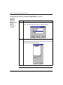
Configuring the Module with Concept . . . . . . . . . . . . . . 51
Selecting Your PLC . . . . . . . . . . . . . . . . . . . . . . . . . . . . . . . . . . 52
Procedure . . . . . . . . . . . . . . . . . . . . . . . . . . . . . . . . . . . . . . . 52
Next. . . . . . . . . . . . . . . . . . . . . . . . . . . . . . . . . . . . . . . . . . . . 55
Setting the Number of NOEs . . . . . . . . . . . . . . . . . . . . . . . . . . .
Introduction . . . . . . . . . . . . . . . . . . . . . . . . . . . . . . . . . . . . . .
Memory Requirements . . . . . . . . . . . . . . . . . . . . . . . . . . . . .
Procedure . . . . . . . . . . . . . . . . . . . . . . . . . . . . . . . . . . . . . .
Next. . . . . . . . . . . . . . . . . . . . . . . . . . . . . . . . . . . . . . . . . . . .
viii
56
56
56
57
58
840 USE 116 00 Version 1.0
Contents
Chapter 5
840 USE 116 00 Version 1.0
Accessing and Editing the I/O Map . . . . . . . . . . . . . . . . . . . . . .
Introduction . . . . . . . . . . . . . . . . . . . . . . . . . . . . . . . . . . . . . .
Procedure . . . . . . . . . . . . . . . . . . . . . . . . . . . . . . . . . . . . . . .
Next . . . . . . . . . . . . . . . . . . . . . . . . . . . . . . . . . . . . . . . . . . .
59
59
59
62
Configuring the Ethernet Address Parameters . . . . . . . . . . . . .
Introduction . . . . . . . . . . . . . . . . . . . . . . . . . . . . . . . . . . . . .
Procedure . . . . . . . . . . . . . . . . . . . . . . . . . . . . . . . . . . . . . . .
How the Module Derives It’s IP Address . . . . . . . . . . . . . . .
63
63
63
65
Transferring Data with the I/O Scanner
140 NOE 771 00 only . . . . . . . . . . . . . . . . . . . . . . . . . . . . 67
I/O Scanner Concepts . . . . . . . . . . . . . . . . . . . . . . . . . . . . . . . .
Introduction . . . . . . . . . . . . . . . . . . . . . . . . . . . . . . . . . . . . . .
I/O Scan List . . . . . . . . . . . . . . . . . . . . . . . . . . . . . . . . . . . . .
I/O Scanner Definitions . . . . . . . . . . . . . . . . . . . . . . . . . . . . .
Peer Cop and Enhanced Modbus/TCP Scanners . . . . . . . .
Peer Cop I/O Scanner Features . . . . . . . . . . . . . . . . . . . . . .
Enhanced Modbus I/O Scanner Features . . . . . . . . . . . . . .
I/O Scanner Support . . . . . . . . . . . . . . . . . . . . . . . . . . . . . .
68
68
68
69
69
70
70
71
Configuring the I/O Scan List Using Concept . . . . . . . . . . . . . . .
Introduction . . . . . . . . . . . . . . . . . . . . . . . . . . . . . . . . . . . . .
IP Address. . . . . . . . . . . . . . . . . . . . . . . . . . . . . . . . . . . . . . .
Unit ID . . . . . . . . . . . . . . . . . . . . . . . . . . . . . . . . . . . . . . . . .
Health Timeout . . . . . . . . . . . . . . . . . . . . . . . . . . . . . . . . . . .
Rep Rate . . . . . . . . . . . . . . . . . . . . . . . . . . . . . . . . . . . . . . .
Read . . . . . . . . . . . . . . . . . . . . . . . . . . . . . . . . . . . . . . . . . .
Write . . . . . . . . . . . . . . . . . . . . . . . . . . . . . . . . . . . . . . . . . . .
Read and Write . . . . . . . . . . . . . . . . . . . . . . . . . . . . . . . . . .
Description . . . . . . . . . . . . . . . . . . . . . . . . . . . . . . . . . . . . . .
Configuring the Health Block . . . . . . . . . . . . . . . . . . . . . . . .
Starting Location of Health Block . . . . . . . . . . . . . . . . . . . . .
72
72
72
72
72
73
73
74
74
74
75
75
Completing the I/O Configuration . . . . . . . . . . . . . . . . . . . . . . . .
Introduction . . . . . . . . . . . . . . . . . . . . . . . . . . . . . . . . . . . . .
Copy and Paste . . . . . . . . . . . . . . . . . . . . . . . . . . . . . . . . . .
Cut and Paste . . . . . . . . . . . . . . . . . . . . . . . . . . . . . . . . . . .
Delete . . . . . . . . . . . . . . . . . . . . . . . . . . . . . . . . . . . . . . . . . .
76
76
76
77
77
ix
Contents
Sort . . . . . . . . . . . . . . . . . . . . . . . . . . . . . . . . . . . . . . . . . . . 77
Fill Down . . . . . . . . . . . . . . . . . . . . . . . . . . . . . . . . . . . . . . . . 78
Configuring the I/O Scan List Using ProWORX NxT . . . . . . . . .
Introduction . . . . . . . . . . . . . . . . . . . . . . . . . . . . . . . . . . . . . .
Selecting Your PLC . . . . . . . . . . . . . . . . . . . . . . . . . . . . . . .
Accessing and Editing the Traffic Cop . . . . . . . . . . . . . . . . .
Setting the Number of NOE’s and
Configuring the Ethernet Address Parameters . . . . . . . . . .
Setting Up the I/O Scanner Using ProWORX NxT . . . . . . .
Specify the Specific I/O Groups to be Scanned . . . . . . . . . .
Configure the Transaction Parameters . . . . . . . . . . . . . . . . .
79
79
80
83
Establishing Configuration Extension Memory for Peer Cop . . .
Introduction . . . . . . . . . . . . . . . . . . . . . . . . . . . . . . . . . . . . .
How Much Memory? . . . . . . . . . . . . . . . . . . . . . . . . . . . . . .
Procedure . . . . . . . . . . . . . . . . . . . . . . . . . . . . . . . . . . . . . .
90
90
90
91
85
88
88
89
Configuring the I/O Scan List Using Modsoft . . . . . . . . . . . . . . . 94
Introduction . . . . . . . . . . . . . . . . . . . . . . . . . . . . . . . . . . . . . 94
Current Limitations . . . . . . . . . . . . . . . . . . . . . . . . . . . . . . . . 95
Storage Requirements . . . . . . . . . . . . . . . . . . . . . . . . . . . . . 95
Specific Input/Output Configuration . . . . . . . . . . . . . . . . . . . 96
Specific Input . . . . . . . . . . . . . . . . . . . . . . . . . . . . . . . . . . . . 98
Specific Input/Output Summary . . . . . . . . . . . . . . . . . . . . . . 99
Other Menu Selectable Support Functions . . . . . . . . . . . . . . 99
The GoToNode Function . . . . . . . . . . . . . . . . . . . . . . . . . . . 99
The AddNode Function . . . . . . . . . . . . . . . . . . . . . . . . . . . 100
The Timeout Function . . . . . . . . . . . . . . . . . . . . . . . . . . . . . 100
Health Bits . . . . . . . . . . . . . . . . . . . . . . . . . . . . . . . . . . . . . 101
OnError Function . . . . . . . . . . . . . . . . . . . . . . . . . . . . . . . . 101
Device IP Address Generation . . . . . . . . . . . . . . . . . . . . . . 101
Chapter 6
Transferring Data with the MSTR Instruction . . . . . . . 103
MSTR Description . . . . . . . . . . . . . . . . . . . . . . . . . . . . . . . . . .
Introduction . . . . . . . . . . . . . . . . . . . . . . . . . . . . . . . . . . . .
MSTR Operations . . . . . . . . . . . . . . . . . . . . . . . . . . . . . . . .
No. of MSTR Instructions Allowed . . . . . . . . . . . . . . . . . . .
x
104
104
104
104
840 USE 116 00 Version 1.0
Contents
MSTR Characteristics. . . . . . . . . . . . . . . . . . . . . . . . . . . . . . . . 105
MSTR Characteristics . . . . . . . . . . . . . . . . . . . . . . . . . . . . 105
MSTR Ladder Logic Representation . . . . . . . . . . . . . . . . . . . .
Ladder Logic Diagram . . . . . . . . . . . . . . . . . . . . . . . . . . . .
Inputs . . . . . . . . . . . . . . . . . . . . . . . . . . . . . . . . . . . . . . . . .
Outputs . . . . . . . . . . . . . . . . . . . . . . . . . . . . . . . . . . . . . . .
Top Node Content . . . . . . . . . . . . . . . . . . . . . . . . . . . . . . .
Middle Node Content . . . . . . . . . . . . . . . . . . . . . . . . . . . . .
Bottom Node Content . . . . . . . . . . . . . . . . . . . . . . . . . . . . .
106
106
106
106
107
107
107
MSTR Function Error Codes . . . . . . . . . . . . . . . . . . . . . . . . . .
Where Displayed. . . . . . . . . . . . . . . . . . . . . . . . . . . . . . . . .
TCP/IP Ethernet Error Codes . . . . . . . . . . . . . . . . . . . . . . .
TCP/IP Ethernet Network Errors . . . . . . . . . . . . . . . . . . . .
CTE Error Codes . . . . . . . . . . . . . . . . . . . . . . . . . . . . . . . .
108
108
108
109
110
Read and Write MSTR Operations . . . . . . . . . . . . . . . . . . . . . 111
Introduction . . . . . . . . . . . . . . . . . . . . . . . . . . . . . . . . . . . . 111
Control Block Utilization . . . . . . . . . . . . . . . . . . . . . . . . . . . 111
Get Local Statistics MSTR Operation . . . . . . . . . . . . . . . . . . . 112
Introduction . . . . . . . . . . . . . . . . . . . . . . . . . . . . . . . . . . . . 112
Control Block Utilization . . . . . . . . . . . . . . . . . . . . . . . . . . . 112
Clear Local Statistics MSTR Operation . . . . . . . . . . . . . . . . . . 113
Introduction . . . . . . . . . . . . . . . . . . . . . . . . . . . . . . . . . . . . 113
Control Block Utilization . . . . . . . . . . . . . . . . . . . . . . . . . . . 113
Get Remote Statistics MSTR Operation . . . . . . . . . . . . . . . . . 114
Introduction . . . . . . . . . . . . . . . . . . . . . . . . . . . . . . . . . . . . 114
Control Block Utilization . . . . . . . . . . . . . . . . . . . . . . . . . . . 114
Clear Remote Statistics MSTR Operation . . . . . . . . . . . . . . . . 115
Introduction . . . . . . . . . . . . . . . . . . . . . . . . . . . . . . . . . . . . 115
Control Block Utilization . . . . . . . . . . . . . . . . . . . . . . . . . . . 115
Peer Cop Health MSTR Operation . . . . . . . . . . . . . . . . . . . . .
Introduction . . . . . . . . . . . . . . . . . . . . . . . . . . . . . . . . . . . .
Control Block Utilization . . . . . . . . . . . . . . . . . . . . . . . . . . .
Peer Cop Communications Health Status Information . . . .
Peer Cop Communications Health Bit State . . . . . . . . . . .
840 USE 116 00 Version 1.0
116
116
116
117
119
xi
Contents
Reset Option Module MSTR Operation . . . . . . . . . . . . . . . . . . 120
Introduction . . . . . . . . . . . . . . . . . . . . . . . . . . . . . . . . . . . . 120
Control Block Utilization . . . . . . . . . . . . . . . . . . . . . . . . . . . 120
Chapter 7
Read CTE (Config Extension Table) MSTR Operation . . . . . .
Introduction . . . . . . . . . . . . . . . . . . . . . . . . . . . . . . . . . . . .
Control Block Utilization . . . . . . . . . . . . . . . . . . . . . . . . . . .
CTE Display Implementation . . . . . . . . . . . . . . . . . . . . . . .
121
121
121
122
Write CTE (Config Extension Table) MSTR Operation . . . . . .
CTE Write Implementation . . . . . . . . . . . . . . . . . . . . . . . . .
Network Implementation . . . . . . . . . . . . . . . . . . . . . . . . . .
Control Block Utilization . . . . . . . . . . . . . . . . . . . . . . . . . . .
CTE Display Implementation . . . . . . . . . . . . . . . . . . . . . . .
123
123
123
123
124
TCP/IP Ethernet Statistics . . . . . . . . . . . . . . . . . . . . . . . . . . . .
Introduction . . . . . . . . . . . . . . . . . . . . . . . . . . . . . . . . . . . .
Board Status Word Bit Definition . . . . . . . . . . . . . . . . . . . .
Board Status Word Bit Definition by Module Type . . . . . . .
125
125
126
126
Embedded Web Pages . . . . . . . . . . . . . . . . . . . . . . . . . 127
Accessing the Web Utility Home Page . . . . . . . . . . . . . . . . . .
Introduction . . . . . . . . . . . . . . . . . . . . . . . . . . . . . . . . . . . . .
How to Access It . . . . . . . . . . . . . . . . . . . . . . . . . . . . . . . .
Schneider Web Utility Home Page . . . . . . . . . . . . . . . . . . .
128
128
128
129
Quantum Welcome Page . . . . . . . . . . . . . . . . . . . . . . . . . . . . 130
Quantum Welcome Page Overview . . . . . . . . . . . . . . . . . . 130
Quantum Welcome Page Links . . . . . . . . . . . . . . . . . . . . . 131
Quantum Local Rack Page . . . . . . . . . . . . . . . . . . . . . . . . . . . 132
Quantum Local Rack Page Overview . . . . . . . . . . . . . . . . 132
Quantum Local Rack Page Links . . . . . . . . . . . . . . . . . . . . 132
CPU Configuration Screen Page . . . . . . . . . . . . . . . . . . . . . . .
CPU Configuration Screen Page Overview . . . . . . . . . . . .
Description Fields . . . . . . . . . . . . . . . . . . . . . . . . . . . . . . .
Register Fields . . . . . . . . . . . . . . . . . . . . . . . . . . . . . . . . . .
ASCII Fields . . . . . . . . . . . . . . . . . . . . . . . . . . . . . . . . . . . .
CPU Configuration Screen Page Links. . . . . . . . . . . . . . . .
xii
133
133
134
134
134
135
840 USE 116 00 Version 1.0
Contents
Ethernet Module Statistics Page . . . . . . . . . . . . . . . . . . . . . . . 136
Ethernet Module Statistics Page Overview . . . . . . . . . . . . . 136
Ethernet Module Statistics Page Links . . . . . . . . . . . . . . . . 137
Remote I/O Communication Status Page . . . . . . . . . . . . . . . . 138
Remote I/O Communication Status Page Overview . . . . . . 138
Remote I/O Communications Status Page Links . . . . . . . . 139
Quantum PLC Data Monitor Page . . . . . . . . . . . . . . . . . . . . . . 140
Quantum PLC Data Monitor Page Overview . . . . . . . . . . . 140
Quantum PLC Data Monitor Page Links . . . . . . . . . . . . . . 141
Configure NOE Page . . . . . . . . . . . . . . . . . . . . . . . . . . . . . . . . 142
Configure NOE Page Overview . . . . . . . . . . . . . . . . . . . . . 142
Configure NOE Page Links . . . . . . . . . . . . . . . . . . . . . . . . 142
Configure SNMP Page . . . . . . . . . . . . . . . . . . . . . . . . . . . . . .
Configure SNMP Page Overview . . . . . . . . . . . . . . . . . . . .
SNMP Page Fields . . . . . . . . . . . . . . . . . . . . . . . . . . . . . . .
Configure SNMP Page Links . . . . . . . . . . . . . . . . . . . . . . .
Completion Message . . . . . . . . . . . . . . . . . . . . . . . . . . . . .
143
143
144
144
145
Configure BOOTP Process . . . . . . . . . . . . . . . . . . . . . . . . . . .
Configure BOOTP Initial Page . . . . . . . . . . . . . . . . . . . . . .
Bootp Node Configuration Form Page . . . . . . . . . . . . . . . .
Initial Configuration . . . . . . . . . . . . . . . . . . . . . . . . . . . . . .
Adding to the BOOTP Database File . . . . . . . . . . . . . . . . .
Changing the BOOTP Database File . . . . . . . . . . . . . . . . .
Deleting from the BOOTP Database File . . . . . . . . . . . . . .
Resetting the Form . . . . . . . . . . . . . . . . . . . . . . . . . . . . . . .
Displaying the BOOTP Database File . . . . . . . . . . . . . . . .
Bootp Node Configuration Form Links . . . . . . . . . . . . . . . .
146
146
147
147
148
148
148
149
149
150
NOE Properties Page . . . . . . . . . . . . . . . . . . . . . . . . . . . . . . . 151
NOE Properties Page Overview . . . . . . . . . . . . . . . . . . . . . 151
NOE Properties Page Links . . . . . . . . . . . . . . . . . . . . . . . . 151
NOE Diagnostics Page . . . . . . . . . . . . . . . . . . . . . . . . . . . . . . . 152
NOE Diagnostics Page Overview . . . . . . . . . . . . . . . . . . . 152
NOE Diagnostics Page Links . . . . . . . . . . . . . . . . . . . . . . . 152
840 USE 116 00 Version 1.0
xiii
Contents
Crash Log Diagnostics . . . . . . . . . . . . . . . . . . . . . . . . . . . . . . 153
Crash Log Diagnostics Page . . . . . . . . . . . . . . . . . . . . . . 153
Crash Log Diagnostics Links . . . . . . . . . . . . . . . . . . . . . . . 154
Contacting Schneider Automation Page. . . . . . . . . . . . . . . . . . 155
Contacting Schneider Automation Page Overview . . . . . . 155
Chapter 8
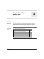
Using the Network Options Ethernet Tester . . . . . . . . 157
Installing the Network Options Ethernet Tester . . . . . . . . . . . . 158
Introduction . . . . . . . . . . . . . . . . . . . . . . . . . . . . . . . . . . . . 158
Installation Procedure . . . . . . . . . . . . . . . . . . . . . . . . . . . . 158
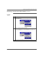
Establishing a Connection with an Ethernet Module . . . . . . . . 159
What You Must Know . . . . . . . . . . . . . . . . . . . . . . . . . . . . 159
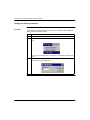
Getting and Clearing Statistics . . . . . . . . . . . . . . . . . . . . . . . . 162
Procedure . . . . . . . . . . . . . . . . . . . . . . . . . . . . . . . . . . . . . . 162
Statistics . . . . . . . . . . . . . . . . . . . . . . . . . . . . . . . . . . . . . . . . . 166
Statistics Description. . . . . . . . . . . . . . . . . . . . . . . . . . . . . . 166
Reading Registers . . . . . . . . . . . . . . . . . . . . . . . . . . . . . . . . . . 168
Reading Registers Procedure. . . . . . . . . . . . . . . . . . . . . . . 168
Writing Registers . . . . . . . . . . . . . . . . . . . . . . . . . . . . . . . . . . . 169
Writing Registers Procedure . . . . . . . . . . . . . . . . . . . . . . . 169
Read or Write Request Error . . . . . . . . . . . . . . . . . . . . . . . 170
Chapter 9
Maintenance . . . . . . . . . . . . . . . . . . . . . . . . . . . . . . . . . . 171
Responding to Errors . . . . . . . . . . . . . . . . . . . . . . . . . . . . . . . .
Detecting Errors . . . . . . . . . . . . . . . . . . . . . . . . . . . . . . . . .
Active LED Error . . . . . . . . . . . . . . . . . . . . . . . . . . . . . . . . .
Ready LED Error . . . . . . . . . . . . . . . . . . . . . . . . . . . . . . . .
Link LED Error . . . . . . . . . . . . . . . . . . . . . . . . . . . . . . . . . .
Kernel LED Error. . . . . . . . . . . . . . . . . . . . . . . . . . . . . . . . .
Fault LED . . . . . . . . . . . . . . . . . . . . . . . . . . . . . . . . . . . . . .
Collision LED Error . . . . . . . . . . . . . . . . . . . . . . . . . . . . . . .
Collision LED, Normal Condition . . . . . . . . . . . . . . . . . . . .
Run LED . . . . . . . . . . . . . . . . . . . . . . . . . . . . . . . . . . . . . . .
Application LED . . . . . . . . . . . . . . . . . . . . . . . . . . . . . . . . .
xiv
172
172
172
173
173
174
174
175
176
176
176
840 USE 116 00 Version 1.0
Contents
Reading and Clearing the Crash Log . . . . . . . . . . . . . . . . . . .
Introduction . . . . . . . . . . . . . . . . . . . . . . . . . . . . . . . . . . . .
The Crash Log . . . . . . . . . . . . . . . . . . . . . . . . . . . . . . . . . .
Reading the Crash Log . . . . . . . . . . . . . . . . . . . . . . . . . . .
Reading the Crash Log via FTP . . . . . . . . . . . . . . . . . . . . .
Clearing the Crash Log . . . . . . . . . . . . . . . . . . . . . . . . . . .
Clearing the Crash Log via FTP . . . . . . . . . . . . . . . . . . . . .
177
177
177
177
177
178
178
Downloading a New NOE Exec . . . . . . . . . . . . . . . . . . . . . . . . 179
Introduction . . . . . . . . . . . . . . . . . . . . . . . . . . . . . . . . . . . . . 179
The Concept Exec Loader . . . . . . . . . . . . . . . . . . . . . . . . . . . . 180
Process . . . . . . . . . . . . . . . . . . . . . . . . . . . . . . . . . . . . . . . 180
Downloading a new NOE Exec via FTP . . . . . . . . . . . . . . . . . . 185
Procedure . . . . . . . . . . . . . . . . . . . . . . . . . . . . . . . . . . . . . . 185
Appendix A
NOE 771 00 Module Specifications . . . . . . . . . . . . . . . 187
Specifications . . . . . . . . . . . . . . . . . . . . . . . . . . . . . . . . . . . . . 188
Specification Table . . . . . . . . . . . . . . . . . . . . . . . . . . . . . . . 188
Appendix B
Ethernet Developers Guide . . . . . . . . . . . . . . . . . . . . . . 189
Overview. . . . . . . . . . . . . . . . . . . . . . . . . . . . . . . . . . . . . . . . . .
Introduction . . . . . . . . . . . . . . . . . . . . . . . . . . . . . . . . . . . . .
References . . . . . . . . . . . . . . . . . . . . . . . . . . . . . . . . . . . . .
What the Sample Application Does. . . . . . . . . . . . . . . . . . .
Development Environment . . . . . . . . . . . . . . . . . . . . . . . . .
190
190
190
190
191
Class Descriptions . . . . . . . . . . . . . . . . . . . . . . . . . . . . . . . . . . 192
List of Classes . . . . . . . . . . . . . . . . . . . . . . . . . . . . . . . . . . 192
The CSample_doc Class . . . . . . . . . . . . . . . . . . . . . . . . . . . . . 194
Description . . . . . . . . . . . . . . . . . . . . . . . . . . . . . . . . . . . . . 194
The CSample_View Class . . . . . . . . . . . . . . . . . . . . . . . . . . . .
What it Does . . . . . . . . . . . . . . . . . . . . . . . . . . . . . . . . . . . .
Accessing TCP/IP . . . . . . . . . . . . . . . . . . . . . . . . . . . . . . .
Application Message Format . . . . . . . . . . . . . . . . . . . . . . .
840 USE 116 00 Version 1.0
195
195
195
196
xv
Contents
Timers and Transaction Processing . . . . . . . . . . . . . . . . . . . . 197
Timers . . . . . . . . . . . . . . . . . . . . . . . . . . . . . . . . . . . . . . . . . 197
Transaction Processing . . . . . . . . . . . . . . . . . . . . . . . . . . . 197
Transmit State Machine . . . . . . . . . . . . . . . . . . . . . . . . . . . . . . 198
Description . . . . . . . . . . . . . . . . . . . . . . . . . . . . . . . . . . . . . 198
Receive State Machine . . . . . . . . . . . . . . . . . . . . . . . . . . . . . . 201
Description . . . . . . . . . . . . . . . . . . . . . . . . . . . . . . . . . . . . . 201
Displaying on the Screen . . . . . . . . . . . . . . . . . . . . . . . . . . . . . 203
Description . . . . . . . . . . . . . . . . . . . . . . . . . . . . . . . . . . . . . 203
Appendix C
Quantum Ethernet TCP/IP
Modbus Application Protocol . . . . . . . . . . . . . . . . . . . 205
Overview . . . . . . . . . . . . . . . . . . . . . . . . . . . . . . . . . . . . . . . . . 206
Introduction . . . . . . . . . . . . . . . . . . . . . . . . . . . . . . . . . . . . 206
Modbus Application Protocol PDU . . . . . . . . . . . . . . . . . . . . . . 207
Example . . . . . . . . . . . . . . . . . . . . . . . . . . . . . . . . . . . . . . . 208
Modbus Application Protocol Service Classes . . . . . . . . . . . .
Introduction . . . . . . . . . . . . . . . . . . . . . . . . . . . . . . . . . . . . .
Data Access . . . . . . . . . . . . . . . . . . . . . . . . . . . . . . . . . . . .
Online Programming . . . . . . . . . . . . . . . . . . . . . . . . . . . . . .
Image Download/Upload . . . . . . . . . . . . . . . . . . . . . . . . . .
Configuration . . . . . . . . . . . . . . . . . . . . . . . . . . . . . . . . . . .
Device Execution State Control . . . . . . . . . . . . . . . . . . . . .
209
209
209
209
209
209
209
Modbus Application Protocol PDU Analysis . . . . . . . . . . . . . . 210
Introduction . . . . . . . . . . . . . . . . . . . . . . . . . . . . . . . . . . . . . 210
Analysis. . . . . . . . . . . . . . . . . . . . . . . . . . . . . . . . . . . . . . . . 210
TCP/IP Specific Issues . . . . . . . . . . . . . . . . . . . . . . . . . . . . . . . 212
Broadcast/Multicast . . . . . . . . . . . . . . . . . . . . . . . . . . . . . . 212
TCP Port Number . . . . . . . . . . . . . . . . . . . . . . . . . . . . . . . . 212
Reference Documents . . . . . . . . . . . . . . . . . . . . . . . . . . . . . . . 213
Introduction . . . . . . . . . . . . . . . . . . . . . . . . . . . . . . . . . . . . 213
xvi
840 USE 116 00 Version 1.0
Contents
Appendix D
NOE 771 00 Module
I/O Scanner Performance Statistics . . . . . . . . . . . . . . 215
140 NOE 771 00 I/O Scanner Performance . . . . . . . . . . . . . .
Quantum 113 CPU . . . . . . . . . . . . . . . . . . . . . . . . . . . . . . .
Quantum 213 CPU . . . . . . . . . . . . . . . . . . . . . . . . . . . . . . .
Quantum 424 CPU . . . . . . . . . . . . . . . . . . . . . . . . . . . . . . .
Quantum 534 CPU . . . . . . . . . . . . . . . . . . . . . . . . . . . . . . .
216
216
217
218
219
Glossary
. . . . . . . . . . . . . . . . . . . . . . . . . . . . . . . . . . . . . . . . . . . . . 221
Index
. . . . . . . . . . . . . . . . . . . . . . . . . . . . . . . . . . . . . . . . . . . . . 229
840 USE 116 00 Version 1.0
xvii
Contents
xviii
840 USE 116 00 Version 1.0
Introduction
1
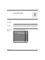
At a Glance
Introduction
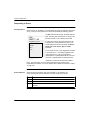
This chapter contains general information about the manual
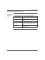
What’s in this
Chapter
This chapter contains the following topics.
Topic
840 USE 116 00
Version 1.0
Page
About this manual
2
System Requirements
6
Related Documentation and Customer Support
7
1
Chapter 1 Introduction
About this Manual
Document Scope
This manual describes all the features of the Quantum 140 NOE 771 00,10/100
Megabit Ethernet module and the Quantum 140 NOE 771 10 Factory/Cast module.
It should provide you with the knowledge to begin using a Quantum Programmable
Logic Controller (PLC) to communicate with devices over an Ethernet network.
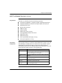
The manual covers:
z
z
z
z
z
z
z
z
z
The hardware architecture of a Quantum Ethernet TCP/IP module designed to
fit into a single slot on the standard Quantum backplane.
The capabilities of the NOE 771 x0 modules.
The installation of the NOE 771 x0 module on a Quantum backplane.
Instructions on configuring the module from your programming panel using
Concept.
Instructions on setting up the module for I/O scanner capabilities (-00 only),
including procedures for configuring the I/O scan list using Concept, ProWORX
NxT, and Modsoft.
Instructions on how to set up the modules to transfer data to and from nodes
on a TCP/IP network through the use of a special master instruction (MSTR).
How to use a World Wide Web embedded server to access diagnostics and
online configurations for the module and its associated controller (PLC).
How to use the FactoryCast web server to customize your configuration via
embedded web pages (-10 module only)
Instructions on using the Network Options Ethernet Tester with a Windows
based PC to monitor the network.
Note: NOE 771 x0 is used in this manual when the information applies to both the
NOE 771 00 and NOE 771 10 modules.
Continued on next page
2
840 USE 116 00
Version 1.0
Chapter 1 Introduction
About this Manual, continued
Who Should Use
this Manual
This manual is intended to support anyone using a Quantum Programmable Logic
Controller that needs to communicate with devices over an Ethernet network. You
are expected to have a knowledge of the use of Programmable Logic Controller
systems and possess of a working knowledge of either the Concept, ProWORX
NxT, or Modsoft programming tools. You also need to understand the use of an
Ethernet network and TCP/IP.
Continued on next page
840 USE 116 00
Version 1.0
3
Chapter 1 Introduction
About this Manual, continued
How this Manual
is Organized
This manual is organized as follows:
Chapter
Description
Chapter 1
Introduction
Presents an introduction to this manual--its scope, who should use
it, how it is organized, and a listing of related publications.
Chapter 2
Product Description
Describes the hardware makeup of the NOE 771 x0, 10/100
Megabit Ethernet Module, and discusses the capabilities of the
features.
Chapter 3
Installing the Module
Describes how to physically install the NOE 771 x0 module into a
Quantum backplane, and how to configure its IP parameters,
SNMP agent, and BOOTP server.
Chapter 4
Configuring the
Module with Concept
Describes how to configure the NOE 771 module from your
programming panel using Concept 2.2 or later.
Chapter 5
Transferring Data with
the I/O Scanner
Discusses the NOE 771 00 module’s I/O scanner capabilities and
includes procedures for configuring the I/O scan list using Concept,
ProWORX NxT, and Modsoft. Module configuration with ProWORX
NxT and Modsoft is also described here.
Chapter 6
Transferring Data with
the MSTR Instruction
Describes how to transfer data to and from nodes on a TCP/IP
network through the use of a special MSTR (master instruction).
The operational statistics and error codes for reading and writing
the controller information are also included.
Chapter 7
Embedding Web
Pages
Discusses how to use an embedded web server to access
diagnostics and through embedded web pages view and change
configurations of the module and its associated controller (PLC).
Chapter 8
Using the Network
Options Ethernet
Tester
Describes how to use the Network Options Ethernet Tester with a
Windows based PC to monitor the network by supplying you with
operational statistics and providing the capability of reading and
writing PLC registers.
Chapter 9
Maintenance
Describes how to obtain information for system maintenance
including accessing and clearing the crash log and downloading the
new NOE Exec.
Continued on next page
4
840 USE 116 00
Version 1.0
Chapter 1 Introduction
About this Manual, continued
Appendices
840 USE 116 00
The manual contains the following Appendices:
Version 1.0
Appendix
Description
Appendix A
NOE 771 x0 Module
Specifications
Describes the main specifications for the Quantum 140 NOE 771
Ethernet Module.
Appendix B
Ethernet Developers
Guide
Describes a sample TCP/IP application named Network Options
Ethernet Tester (NOET) used to verify the installation of the
Quantum Ethernet TCP/IP modules and serves as a sample
application for developers.
Appendix C
Quantum Ethernet
TCP/IP Modbus
Application Protocol
Describes the Modbus Application Protocol used to transport
Modbus Application Protocol PDUs over TCP/IP.
Appendix D
NOE 771 00 Module
I/O Scanner
Performance
Statistics
Provides graphs of performance statistics for the I/O Scanner used
with various CPUs.
5
Chapter 1 Introduction
System Requirements
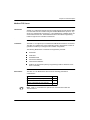
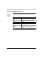
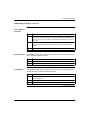
Minimum System
Requirements
6
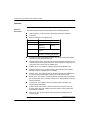
The following table details the minimum versions for systems used with the NOE
771 x0 modules:
System
Minimum Version Number
Quantum Executive
2.0
Concept
2.2
Modlink
2.0
Modsoft
2.6
ProWORX NxT
2.0 IP Address Configuration
2.1 I/O Scanning
840 USE 116 00
Version 1.0
Chapter 1 Introduction
Related Documentation and Customer Support
Related Paper
Documentation
In addition to the manual, the following documents may prove helpful to you:
z
z
z
z
z
z
z
z
Concept 2.2 User’s Manual, 840 USE 483 00
BOOTP Lite User Documentation, 31002087
FactoryCast User Guide, 890 USE 152 00
Ladder Logic Library User Guide, 890 USE 100 00
Modbus Protocol Reference Guide, PI-MBUS-300
Open Modbus Specification, www.modicon.com/openmbus
ProWORX NxT User Guide, 372 SPU 680 01 NMAN
RIO Manual, 890 USE 101 00
Related
Electronic
Documentation
The NOE 771 x0 contains an embedded web server to provide online diagnostics,
configuration, and support. The NOE 77710 module has additional functionality
provided by the FactoryCast module.
Customer
Support
If you have any problems, please consult the documentation listed above or MSWindows documentation first. If you still have a question or need assistance, help
is available from our Schneider hotline:
z
z
z
z
Tel: USA and Canada 800-468-5342
Tel: International 978-975-9557
Fax: All 978-975-9301
BBS: Bulletin Board 978-975-9779
When calling the Schneider 800 telephone number, you will get a recording asking
you to enter a one-digit code for the type of service you request, provided you use
a touch tone telephone.
Continued on next page
840 USE 116 00
Version 1.0
7
Chapter 1 Introduction
Related Documentation and Customer Support, continued
Customer
Support,
continued
8
Visit Our Web Site: Please access the Schneider web site, www.modicon.com or
schneider.com for the most up-to-date NOE Ethernet Controller information, such
as resolutions to product issues, and product announcements. When you access
the web site, look under technical information, and choose Quantum from the list of
cross-product families. Then access Resolutions for resolutions to product issues,
Product Manuals for the most recently published user documentation, and so on.
840 USE 116 00
Version 1.0
Product Description
2
At a Glance
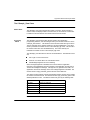
Introduction
This chapter presents a product overview of the Quantum 140 NOE 771 00 10/100
Megabit Ethernet Module and the Quantum 140 NOE 771 10 FactoryCast Module.
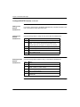
What’s in this
Chapter
This chapter contains the following topics.
Topic
NOE 771 x0 Module Overview
840 USE 116 00
Version 1.0
Page
10
LED Indicators
13
Connectors and Cabling
15
I/O Scanner
16
Peer-to-Peer Communications
18
Modbus/TCP Server
19
FTP and HTTP Services
20
BOOTP Server
22
SNMP
23
9
Chapter 2 Product Description
NOE 771 x0 Module Overview
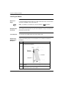
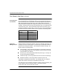
General
Description
The Quantum 140 NOE 771 00,10/100 Ethernet module, shown below, is the latest
model in a line of Quantum Ethernet TCP/IP modules designed to make it possible
for a Quantum Programmable Logic Controller (PLC) to communicate with devices
over an Ethernet network. The NOE 771 x0 module’s electronics are contained in a
standard Quantum single width housing that takes up one slot in a Quantum
backplane. The module can be plugged into any available slot in the backplane and
is capable of being hot swapped.
The NOE 771 00 provides real-time
peer-to-peer communications, as well
as, I/O scanning, and a Modbus/TCP
server. The included HTTP services
provide maintenance and
configuration utilities to the module.
The NOE 771 10 provides all the
services of the -00 except the I/O
Scanner. It also has the following
additional features:
z user programmable web pages
z the FactoryCast application,
including:
creating and viewing of graphic
real-time templates using Java beans
creating and viewing of text realtime templates in spreadsheet format
use of Concept symbols or direct
addresses.
Continued on next page
10
840 USE 116 00
Version 1.0
Chapter 2 Product Description
NOE 771 x0 Module Overview, continued
Key Features
The NOE 771 x0 module provides the following key features:
z
z
z
z
z
z
z
z
z
z
z
z
Front Panel
Components
Integrated 10/100BASE-TX, full duplex capable, shielded twisted pair port
Integrated 100BASE-FX multimode, full duplex capable, fiber optic port
Embedded HTTP server
BOOTP client and server
SNMP V2 agent
Flash file system
Modbus I/O scanner (-00 only)
Field upgradeable software over TCP/IP
Modbus/TCP client
Modbus/TCP server
User Programmable Web Pages (-10 only)
FactoryCast Application (-10 only)
The front panel of NOE 771 x0 module contains identification marking, color code,
and LED display. A writable area for an Internet Protocol (IP) address, a global
address label, and two Ethernet cable connectors are located behind the
removable front panel door. The following table provides a description of the front
panel components which are shown on the opposite page.
Component
Description
LED indicator Panel
Indicates the operating status of the module, and the fiber
optic and Modbus communications networks it is connected
to. (See LED Indicators in this chapter.)
IP Address Writable
Area
Provides a writable area to record the module’s assigned IP
address.
Global Address Label
Indicates the module’s global Ethernet MAC address
assigned at the factory.
100 BASE-FX
Connector
Provides an MT-RJ receptacle for connection to a 100
megabit fiber optic Ethernet cable.
10/100BASE-T
Connector
Provides an RJ-45 receptacle for connection to a shielded,
twisted pair Ethernet cable.
Continued on next page
840 USE 116 00
Version 1.0
11
Chapter 2 Product Description
NOE 771 x0 Module Overview, continued
Front View
The front of the NOE 771 00 Ethernet module is shown below. The 140 NOE 771
10 is identical, with the exception of the Module Description, which reads 140 NOE
771 10 FactoryCast.
Model Number
Module Description
Color Code
LED Display
140
NOE 771 00
Ethernet 10/100
Active
Ready Fault
Run
Coll
Link
Tx Act
Rx Act
10MB
Removable Door
100MB Fduplex
Kernel Appl
WRITE ASSIGNED IP ADDRESS ABOVE
Do Not Duplicate Address
Use Permanent Felt-tip Pen
IP Address
Writable Area
Global Address Label
100 Base Fx
MT-RJ Cable Connector
10/100 Base-T
RJ-45 Cable Connector
12
Base
Fx
00
-T
840 USE 116 00
Version 1.0
Chapter 2 Product Description
LED Indicators
LED Indicator
Panel
The LED indicator panel, shown below, provides continuous operating information
about the NOE 771 x0 module and its connection to the network. The functions of
the LED indicators are described in the following table
LED
Color
Description
Active
Green Indicates the backplane is configured.
Ready
Green Indicates module is healthy.
Fault
Red
Run
Green Flashes to indicate diagnostic code, as
described in “Run LED Status” (below).
Tx Act
Coll.
Red
Rx Act
Link
Green On when Ethernet link is active.
10MB
Tx Act
Green Flashes to indicate Ethernet transmission.
100MB
Fduplex
Rx Act
Green Flashes to indicate Ethernet reception.
Kernel
Appl
Kernel
Amber On when in Kernel Mode.
10MB
Green On when the module is connected to a 10
Megabit network.
100MB
Green On when the module is connected to a
100 Megabit network.
Fduplex
Appl
Indicates when the NOE is in a crash state
Flashes when Ethernet collisions occur.
Active
Ready
Fault
Run
Coll
Link
On when Ethernet is operating in the full
duplex mode.
Green On when crash log entry exists.
Continued on next page
840 USE 116 00
Version 1.0
13
Chapter 2 Product Description
LED Indicators, continued
Run LED Status
The state of the Run LED indicator provides the following diagnostic information:
Indicator State
Status
On (steady)
Normal operation: The NOE module is ready for network
communication.
Number of flashes in sequence
one
14
Not used
two
Not used
three
No Link: the network cable is not connected or is defective
four
Duplicate IP address: The module will stay off-line.
five
No IP address: The module is attempting to obtain an IP address
from a BOOTP server.
six
Using default IP address
seven
No valid executive NOE present
840 USE 116 00
Version 1.0
Chapter 2 Product Description
Connectors and Cabling
10/100 BASE-T
Twisted Pair
Connector
The NOE 771 x0 module’s 10/100 BASE-T connector (shown below) is a standard
RJ-45 twisted pair receptacle.
Pins
8
1
Schneider Automation recommends that you use Category 5 STP cabling, which is
rated to 100 Mbps, with an RJ-45 connector.
The eight pins are arranged vertically and numbered in order from the bottom to the
top. The RJ-45 pinout used by this module is:
z
z
z
z
100 BASE-FX
Receive Data (+)
3
Receive Data (-)
6
Transmit Data (+)
1
Transmit Data (-)
2
The NOE 771 x0 module’s 100 BASE-FX connector is a MT-RJ receptacle with it’s
mating fiber optic cable connector (see figure on page 4).
For the NOE 771 x0, you may need an MT-RJ to SC (Duplex) Multimode fiber optic
cable assembly 62.5/125µm. Schneider Electric recommends Cable Number
490NOC00005 to connect to fiber hubs/switches.
Note: The NOE 771 x0 is a one channel device. It is capable of communicating
over either a 10/100BASE-T or a 100BASE-FX Ethernet network at any given time,
but not both at the same time.
840 USE 116 00
Version 1.0
15
Chapter 2 Product Description
I/O Scanner (140 NOE 771 00 only)
Introduction
The functionality of your NOE 771 00 module is further enhanced by the addition of
a Modbus I/O Scanner which you can configure with either the Modsoft or Concept
programming panel. This allows you a way to transfer data between network
nodes without using the MSTR instruction.
You can configure the NOE 771 Modbus I/O Scanner by either of two methods:
z
z
Peer Cop
Ethernet I/O Scanner
Note: It is recommended that the enhanced Modbus I/O Scanner be used for all
new installations. Peer Cop functionality is provided only on as an easy migration
path for an existing installation. The enhanced Modbus I/O Scanner provides
greater functionality than the Peer Cop based I/O scanner.
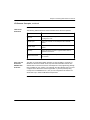
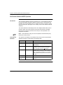
Peer Cop Based
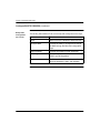
I/O Scanner
The Peer Cop based Modbus I/O Scanner has the following characteristics:
Parameter
Value
Max. No. of Devices
64
Max. No. of Input Words
500
Max. No. of Output Words
500
HealthTimeout Value
Global Setting (20 Msec to 2 Secs in 20 mSec increments)
Input TimeOutState
Global Setting (Zero or Hold)
IP Address
Derived from Modbus Address (must be on NOE’s Subnet)
Remote Register Reference Not configurable - 400001 is used
Continued on next page
16
840 USE 116 00
Version 1.0
Chapter 2 Product Description
I/O Scanner (140 NOE 771 00 only), continued
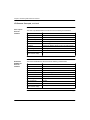
Enhanced
Modbus I/O
Scanner
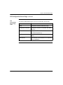
The Enhanced based Modbus I/O Scanner has the following characteristics
Parameter
Value
Max. No. of Devices
64
Max. No. of Input Words
4,000
Max. No. of Output Words
4,000
HealthTimeout Value
Individual Setting (1 Msec to 2 Secs in 1 mSec increments)
Input TimeOutState
Individually Settable
IP Address
Individually Settable
Remote Register Reference Configurable
Min. Update Rate
Settable
Refer to Chapter 5 to learn how to configure the Modbus I/O Scanner.
Refer to Appendix D for detailed performance data.
Performance
840 USE 116 00
Version 1.0
Refer to Appendix D for detailed performance data.
17
Chapter 2 Product Description
Peer-to-Peer Communications
Introduction
All NOE 771 x0 Quantum Ethernet TCP/IP modules provide the user with the
capability of transferring data to and from nodes on a TCP/IP network through the
use of a special MSTR (master instruction). All PLCs that support networking
communication capabilities over Ethernet can use the MSTR ladder logic
instruction to read or write controller information.
MSTR
Operations
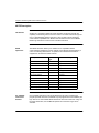
The MSTR instruction allows you to initiate one of 12 possible network
communications operations over the network. Each operation is designated by a
code. The following table lists the 12 operations and indicates those that are
supported on an Ethernet TCP/IP network.
MSTR Operation
Performance
Code
TCP/IP Ethernet Support
Write data
1
supported
Read Data
2
supported
Get local statistics
3
supported
Clear local statistics
4
supported
Write global database
5
not supported
Read global database
6
not supported
Get remote statistics
7
supported
Clear remote statistics
8
supported
Peer Cop health
9
supported
Reset Option Module
10
supported
Read CTE(config extension)
11
supported
Write CTE (config extension)
12
supported
Performance information to be inclused in manual revision 1.1.
Refer to Chapter 6 for the Number of MSTR Instructions allowed.
18
840 USE 116 00
Version 1.0
Chapter 2 Product Description
Modbus/TCP Server
Introduction
All NOE 771 x0 Quantum Ethernet TCP/IP modules provide the user with the ability
to access data from the controller using the standard Modbus/TCP protocol. Any
device: PC, HMI package, another PLC, or any Modbus/TCP compliant device can
access data from the PLC. The Modbus/TCP Server also allows Programming
Panels to login into the controller over Ethernet.
L
Limitations
The NOE 771 x0 supports up to 32 simultaneous Modbus/TCP Server connections.
The NOE 771 x0 allows only one Programming Panel to be logged in at a time to
guarantee consistency of changes to the controller configuration.
The following Modbus/TCP commands are supported by the NOE:
z
z
z
z
z
z
Performance
Read Data
Write Data
Read/Write Data
Get Remote Statistics
Clear Remote Statistics
Modbus 125 Commands (used by Programming Panels to download a new
Exec to the NOE)
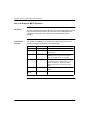
The NOE 771 x0’s Modbus/TCP Server has the following performance
characteristics:
Parameter
Value
Typical Response Time (mSec)
0.6
Number of Modbus/TCP Server Connections
32
Number of Simultaneous Login Channels
1
Note: NOE 771 x0 Modbus/TCP performance measurements made with
140 CPU 534 14.
840 USE 116 00
Version 1.0
19
Chapter 2 Product Description
FTP and HTTP Services
FTP Server
The NOE 771 x0’s File Transfer Protoc Protocol (FTP) server is available as soon
as the module has received an IP address. Any FTP client can logon to the module
if it has the correct user name and password. The FTP server provides the
following services:
•
•
•
update the NOE’s firmware by downloading a new Exec
error log visibility by uploading error log files
upload/download BOOTP server and SNMP configuration files
The default user name is USER, and the default password is USERUSER. Both the
user name and password are case sensitive. Refer to Chapter 3 for instructions on
how to change the password, and add or delete user names to the FTP server.
There should be only one FTP client per module.
Continued on next page
20
840 USE 116 00
Version 1.0
Chapter 2 Product Description
FTP and HTTP Services, continued
HTTP Server
The NOE 771 x0’s HyperText Transport Protocol (HTTP) server is available as
soon as the module has received an IP address. It can be used with version 4.0 or
greater, of either the Internet Explorer or Netscape browsers, and allows you to
see:
•
•
•
module Ethernet statistics
controller and I/O information
BOOTP server information
The HTTP server’s HTML pages allow you to configure the module’s BOOT server
and SNMP Agent.
The HTTP server is protected with a default name and password. The default name
and password are both USER, and both are case sensitive. They can both be
changed via the Configuration page on the NOE 771 x0’s Web Embedded Pages
(see Chapter 3).
The NOE 771 x0 supports a maximum of 32 HTTP instantaneous connections.
Note: Browsers may open multiple connections so 32 HTTP connections does not
indicate 32 simultaneous users.
Note: The NOE 771 00 module does not support user downloaded Web pages.
You will need to purchase the 140 NOE 771 10 module in order to support that
requirement.
840 USE 116 00
Version 1.0
21
Chapter 2 Product Description
BOOTP Server
Introduction
The BOOTstrap Protocol (BOOTP) software, compliant with RFC 951, is used to
assign IP addresses to nodes on an Ethernet network. Devices (hosts) on the
network issue BOOTP requests during their initialization sequence and a BOOTP
server that receives the requests will extract the required IP address information
from its database and place it in BOOTP response messages to the requesting
devices. The devices will use the assigned IP addresses, received from the
BOOTP server, for all communication occurring on the network.
Your NOE
BOOTP Server
Your NOE 771 x0 module comes supplied with a BOOTP server. This feature
allows you to provide IP addresses to all the I/O devices being serviced by the NOE
771 00. Providing a BOOTP server that is built into your NOE 771 x0 module,
eliminates the need for you to have a dedicated PC on your IO network acting as a
BOOTP server.
Note: The NOE 771 x0’s BOOTP server cannot be used to provide it’s own IP
address.
You can configure your NOE 771 x0’s BOOTP server from the module’s HTTP web
page. Using this feature allows you to add, remove, and edit devices to the BOOTP
server’s database which is maintained on the module’s non-volatile memory. Refer
to Chapter 7 to learn how to configure the BOOTP server’s database.
22
840 USE 116 00
Version 1.0
Chapter 2 Product Description
SNMP
Introduction
Network management software allows a network manager to monitor and control
network components and thus make it possible to isolate problems and find their
causes. It allows a manager to:
z
z
Manager/Agent
Paradigm
interrogate devices such as host computer, routers, switches, and bridges to
determine their status, and
obtain statistics about the networks to which they attach.
Network management software follows the conventional client-server model. To
avoid confusion with other network communication protocols that use the client/
server terminology, network management software uses the terms;
z
z
manager for the client application that runs on the manager’s computer
agent for the application that runs on a network device.
The manager uses conventional transport protocols (e.g., TCP or UDP) to establish
communication with the agent and they then exchange request and responses
according to the network management protocol.
Simple Network
Management
Protocol
Your NOE 771 x0 module is configured with the Simple Network Management
Protocol (SNMP) which is the standard protocol used to manage a local area
network (LAN). It defines exactly how a manager communicates with an agent,
(i.e., the format of the requests that a manager sends to an agent and the format of
the replies that the agent returns to the manager).
The MIB
Each object to which SNMP has access must be defined and given a unique name.
Also, both the manager and agent programs must agree on the names and the
meanings of fetch and store operations. The set of all objects SNMP can access is
known as a Management Information Base (MIB).
Continued on next page
840 USE 116 00
Version 1.0
23
Chapter 2 Product Description
SNMP, continued
ASN.1 Naming
Scheme
Objects in a MIB are defined with the
ASN.1 naming scheme, which assigns
each object a long prefix that
guarantees the name will be unique. For
example, an integer that counts the
number or IP datagrams a device has
received is named:
iso.org.dod.internet.mgmt.mib.ipInReceives
This object name is represented in an
SNMP message by assigning each part
an integer. So, the above message
would appear as follows:
1.3.6.1.2.1.4.3
with each integer having the following
meaning:
1 = ISO (International Organization
for Standardization
3 = identified organization — one of
branches under the ISO root
6 = U. S. Department of Defense
(DOD) — one of the children under
branch1.3
1 = the Internet subtree under 1.3.6
2 = the mgm branch — (one of
seven) of the Internet subtree. It is
managed by the Internet Assigned Numbers Authority, and includes the
standard MIBs.
1 = mib-2(1) group of managed objects
4 = ip — the mib-2(1) IP group (one of 11)
3 = ipinReceivers — the MIB object
The Object
Identifier (OID)
In the above example, the MIB object identified by the notation 1.3.6.1.2.1.4.3 is
referred to as the Object Identifier or OID. All OIDs can be envisioned as part of a
tree structure which begins at the root (ISO) and branches out with each subtree
identified by an integer.
Continued on next page
24
840 USE 116 00
Version 1.0
Chapter 2 Product Description
SNMP, continued
SNMP Protocol
Data Units
SNMP uses Protocol Data Units (PDUs) to carry the requests and responses,
between the manager and the agents, for the information contained in an OID. As
the following figure shows, the SNMP message is the innermost part of a typical
network transmission frame.
The PDUs within the SNMP initiate the communication between the manager and
the agents. The SNMP installed on your NOE 771 00 module uses three PDUs:
•
•
•
GetRequest
SetRequest
Trap
GetRequest PDU
The GetRequest (shortened to Get) PDU is used by the SNMP manager to retrieve
the value of one or more objects (OIDs) from an agent.
SetRequest PDU
The SetRequest (shortened to Set) PDU is used by the SNMP manager to assign a
value to one or more objects (OIDs) residing in an agent.
Trap PDU
The Trap PDU is used by the agent to alert the manager that a predefined event
has occurred.
Continued on next page
840 USE 116 00
Version 1.0
25
Chapter 2 Product Description
SNMP, continued
Version &
Community
Identifiers
The version identifies the version number of the SNMP software being used by the
manager and the agent. Your NOE 771 x0 supports Version 2 of the SNMP. The
community is an identifier that you assign to your SNMP network. If community
names for the manager and the agent don’t agree, the agent will send an
authentication failure trap message to the manager. If the community names and
version number agree, the SNMP PDU will be processed.
What can be
Configured
Your NOE 771 x0 module can be configured to send an authentication trap to two
SNMP managers if it receives a community name in a Get/Set request that does
not match the configured name. Also, you can configure the Sys Contact and Sys
Location via the configuration page in the module’s Embedded Web pages. Please
refer to Chapter 7 to learn how to configure the NOE 771 x0 SNMP.
26
840 USE 116 00
Version 1.0
Installing the Module
3
At a Glance
Introduction
This chapter describes how to physically install the NOE 771 x0 module into a
Quantum backplane, and configure its IP parameters, SNMP agent, and BOOTP
server.
What’s in this
Chapter
This chapter contains the following topics.
Topic
840 USE 116 00
Version 1.0
Page
Before You Begin
28
Cabling Schemes
30
Security
33
Installing the module
34
Connecting the Cable
35
Assigning Ethernet Address Parameters
36
Establishing the FTP Password
41
Establishing the HTTP Password
46
Using BOOTP Lite to Assign Address Parameters
49
27
Chapter 3 Installing the Module
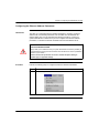
Before You Begin
Initial Checks
Before you install your module, you need to:
z
z
determine how the NOE 771 x0 module will be assigned its Ethernet address
parameters (the default method is BOOTP)
verify that your Ethernet network is properly constructed
CAUTION
DUPLICATE ADDRESS HAZARD
Do not connect the module to your network until you have ensured that its IP address will
be unique on the network. Having two devices with the same IP address can cause
unpredictable operation of your network.
Failure to observe this precaution can result in network disruption leading to
possible injury or equipment damage.
Determining the
Appropriate
Ethernet
Address
Parameters
Consult your system administrator to determine if you must configure a new IP
address and appropriate gateway and subnet mask addresses, or whether the
module will obtain its Ethernet address parameters from a BOOTP server. If the
administrator assigns new address parameters, follow the directions in Chapter 4
to configure the module from your programming panel.
Note: If you will be changing the default configuration, you should stop the
controller, then install the module, then change the configuration before starting the
controller again.
The NOE 771 x0 module only reads its configuration data at power-up and when it
is reset. Whenever the configuration data is changed, the module must be reset,
either by hot swapping or through a reset command in the MSTR block (see Reset
Option Module MSTR Operation section in Chapter 6). Once the module is
installed, stopping and restarting the controller will not reset it.
Continued on next page
28
840 USE 116 00
Version 1.0
Chapter 3 Installing the Module
Before You Begin, continued
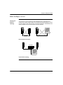
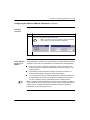
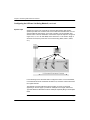
Verifying the
Network
Topology
You should not connect an Ethernet web embedded server module directly to
another device with a length of cable. For the network to operate properly, you must
route the cable for each device through an Ethernet hub/switch. Hubs/switches are
widely available and can be purchased from many suppliers.
NOE
NOE
NOE
Improper Network Topologies
NOE
NOE
Hub/Switch
Proper Network Topology
840 USE 116 00
Version 1.0
29
Chapter 3 Installing the Module
Cabling Schemes
Introduction
In a standard Ethernet cabling scheme, each device connects via a cable to a port
on a central Ethernet hub/switch.
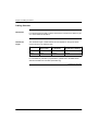
Twisted Pair
Length
The maximum length of cable between devices depends on the type of device
used, as shown in the following table:
Type of Device
Max. Cable from
Device to Hub
Max. Hubs Between Max. Cable Between Most
Any Two Nodes
Distant Nodes on Network
Hub
100 m
4
500 m
Switch
100 m
Unlimited
Unlimited
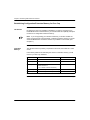
For Fast Ethernet (100 Base-T) specifications, please refer to the IEEE 802.3u
Standard available from the IEEE (www.IEEE.org).
Continued on next page
30
840 USE 116 00
Version 1.0
Chapter 3 Installing the Module
Cabling Schemes, continued
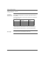
Cabling with
Traditional Hubs
The following illustration and tables show the maximum number of hubs and the
maximum cable length between devices when using hubs.
10 BASE-T Cable
Distances
The illustration below is for 10 BASE-T cable:
100 BASE-T
Cable Distances
The 100 BASE-T cabling allows for two hubs with a link maximum distance of
100 m (325 ft), and a total network diameter of 205 m (665 ft).
The following table details the maximum distance parameters with 100 BASE-T:
Model
Length max. in Twisted pair TX-T2-T4
DTE-DTE (no repeater)
100 m (325 ft)
One Class I repeater
200 m (650 ft)
One Class II repeater
200 m (650 ft)
Two Class II repeaters
205 m (665 ft)
Continued on next page
840 USE 116 00
Version 1.0
31
Chapter 3 Installing the Module
Cabling Schemes, continued
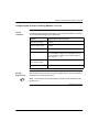
100 BASE-FX
Cable Distances
The 100 BASE-FX cabling allows for two hubs with a link maximum distance of
412 m (1339 ft).
The following table details the maximum distance parameters with 100 BASE-FX
and 100 BASE TX-FX:
Model
Length max. Twisted pair TX
and Fiber FX
DTE-DTE (no repeater) n.a.
Length max.
Fiber FX
412 m (1339 ft)
One Class I repeater
260.8 m (1)
272 m (884 ft)
One Class II repeater
308.8 m (1)
320 m (1040 ft)
Two Class II repeaters
216.2 m (2)
228 m (741 ft)
(1) Mixed twisted pairs and fiber assumes a 100 m (325 ft) twisted pair links
(2) Mixed twisted pairs and fiber assumes a 105 m (340 ft) twisted pair links
Fiber Length
32
The maximum length for 850 nm/Multimode cable is 2 KM.
840 USE 116 00
Version 1.0
Chapter 3 Installing the Module
Security
Overview
To restrict access to your Ethernet controller and I/O network, you may want to
consider a firewall. A firewall is a gateway which controls access to your network.
Types of
Firewalls
There are two types of firewalls:
z
z
Network-level firewalls
Application-level firewalls
Network-Level
Firewalls
Network-level firewalls are frequently installed between the Internet and a single
point of entry to an internal, protected network.
ApplicationLevel Firewalls
An application-level firewall acts on behalf of an application. It intercepts all traffic
destined for that application and decides whether to forward that traffic to the
application. Application-level firewalls reside on individual host computers.
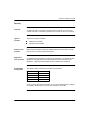
Port Numbers
Used by NOE
The following table contains the port numbers used by NOE.
Protocol
Port Number
Modbus/TCP
TCP 502
HTTP
TCP 80
SNMP
UDP 61
FTP
TCP 21
You may need to provide this information to your system administrator to configure
the firewall to allow access to your PLC from outside of your facility.
840 USE 116 00
Version 1.0
33
Chapter 3 Installing the Module
Installing the Module
Before You
Begin
Locate the backplane that the NOE 771 module will be mounted in. Ensure that an
open slot is available to mount the module in.
Note: The NOE 771 x0 module can only be installed in a local backplane.
Backplane Slot
Placement
The modules may be placed in any slot in the backplane. They do not have to be
placed next to each other.
Tools Required
You will need one Phillips head screw driver-medium size.
Mounting the
Module in the
Backplane
Perform the following steps to mount the NOE 771 x0 module in a Quantum
backplane..
34
Step
Action
1
Holding the module at an angle, mount it on to the two hooks located
near the top of the backplane.
2
Swing the module down so its connector engages the backplane
connector.
3
Using a Phillips head screw driver, tighten the screw at the bottom of the
module between 2 and 4 in-lbs of torque.
840 USE 116 00
Version 1.0
Chapter 3 Installing the Module
Connecting the Cable
+
Note: The 140 NOE 771 x0 is capable of communicating over either a 10/
100BASE-T or a 100BASE-FX Ethernet network at any given time, but not both at
the same time
Shielded
Twisted Pair
If you are using shielded twisted pair cable, Schneider Electric recommends
Category 5, which is rated to 100 Mbps. The following table specifies the Schneider
Electric part numbers:
Purpose/Description
Part Number
Available Lengths in meters
Connection of a device to an Ethernet hub/switch
Shielded Twisted Pair Cable
(SFTP, Cat 5, RJ-45,
Low Smoke Free Halogen)
490NTW000nn
02, 05, 12, 40, 80
(where nn is the
length in meters)
Connection of the Ethernet hub/switch together
Shielded Twisted Pair crossed
Cable (SFTP, Cat 5, RJ-45,
Low Smoke Free Halogen)
490NTC000nn
05,15,40, 80
(where nn is the
length in meters)
Use RJ-45 connectors. Slip the connector into the port. It should snap into place.
Fiber Optic
840 USE 116 00
Remove the protective plug from the module’s MT-RJ connector port and the
protective cap from the tip of the black connector on the MT-RJ fiber optic cable
(see figure below). Note the position of the keyway on the module’s connector port
and the matching key on the cable connector, and then insert the connector into the
port. It should snap into place.
Version 1.0
35
Chapter 3 Installing the Module
Assigning Ethernet Address Parameters
Overview
As shipped from the factory, the NOE 771 x0 module does not contain an IP
address. This is also true if you have not programmed the unit with an Ethernet
configuration extension. In this condition, when the module starts up, it will attempt
to obtain an IP address from the network’s BOOTP server.
You can use Concept to assign an IP address, default gateway and sub network
mask. See Configuring the Ethernet Address Parameters in Chapter 4.
You can also assign IP address parameters using the BOOTP Lite software utility.
See Using BOOTP Lite to Assign Address Parameters in this chapter.
CAUTION
DUPLICATE ADDRESS HAZARD
Be sure that your NOE 771 x0 module will receive a unique IP address. Having two or more
devices with the same IP address can cause unpredictable operation of your network.
Failure to observe this precaution can result in injury or equipment damage.
Using a BOOTP
Server
A BOOTP server is a program which manages the IP addresses assigned to
devices on the network. Your system administrator can confirm whether a BOOTP
server exists on your network and can help you use the server to maintain the
adapter’s IP address.
How an
unconfigured
(“as shipped”)
module obtains
an IP address
On startup, an unconfigured NOE 771 x0 module will attempt to obtain an IP
address by issuing BOOTP requests. When a response from a BOOTP server is
obtained, that IP address will be used. If there is no BOOTP response received in
two minutes, the module will use the default IP Address.
Continued on next page
36
840 USE 116 00
Version 1.0
Chapter 3 Installing the Module
Assigning Ethernet Address Parameters, continued
Using the Default
IP Address
To use the default IP address with your PC, set up an active route from your PC. To
do this with either Windows 95 or Windows NT, use the following procedure.
Step
Action
1
Be sure the NOE module is running
2
Obtain the default IP address of the NOE
3
Open an MS-DOS Window
4
Print the current active routes by typing:
C:\>route print
5
Add an active route for the local NOE by typing:
C:\>route add 84.0.0.0 mask 255.0.0.0 205.217.193.205
The result is that Windows 95/98/ NT will now talk to any address that starts with
an 84 that is directly connected to a hub or switch directly accessible to your
machine, or that can be seen by the route/gateway specified.
Continued on next page
840 USE 116 00
Version 1.0
37
Chapter 3 Installing the Module
Assigning Ethernet Address Parameters, continued
Using the Default
IP Address,
continued
Step
Action
6
Confirm that there is a new entry in the active route table by typing:
C:>route print
7
Verify that a connection is made by typing
C:\>ping 84.0.0.2
Specifying
Address
Parameters
Consult your system administrator to obtain a valid IP address and appropriate
gateway and subnet mask, if required. Then follow the instructions in Configuring
the Ethernet Address Parameters in Chapter 4.
Continued on next page
38
840 USE 116 00
Version 1.0
Chapter 3 Installing the Module
Assigning Ethernet Address Parameters, continued
Assigning an IP
address Via
Concept’s
“Specify IP
Address” option.
You can select the NOE 771 x0 module’s “Specify IP Address” mode via Concept to
assign an IP address (as well as default gateway and sub network mask) to the
module.
Assigning an IP
address Via
Concept’s “Use
Bootp Server”
option
You can select the NOE 771 x0 module’s “Use Bootp Server” mode via Concept to
instruct the module to obtain its IP address from a network BOOTP server. In this
mode, only an address obtained from a BOOTP server will be accepted by the
module.
If BOOTP Server
Responds
If the server responds with address parameters, the NOE 771 x0 module will use
those parameters as long as power remains applied to the module.
If the server doesn’t respond, the module will retry its request for two minutes.
If BOOTP Server
Doesn’t Respond
If no BOOTP response is received, the NOE 771 x0 module will use the default IP
Address.
During this time the Run indicator will display a pattern of three flashes.
840 USE 116 00
Version 1.0
39
Chapter 3 Installing the Module
Assigning Ethernet Address Parameters, continued
NOE 771 00
Duplicate IP
Address Test
In all cases, when the NOE 771 x0 module receives an IP address, it will test for
duplicate addresses by sending broadcast ARP requests three times at 5 second
intervals.
If a Duplicate IP Address is found on the network, the NOE 771 x0 will stay off-line
to avoid a network disruption. It will display a pattern of four flashes to indicate a
Duplicate IP Address detection.
Gratuitous ARP
40
If there are no replies to its requests, it will send gratuitous ARP three times at 2
second intervals to announce its presence on the network.
840 USE 116 00
Version 1.0
Chapter 3 Installing the Module
Establishing the FTP Password
Establishing the
FTP Password
The FTP Password is established using the Embedded Web Server. This section
contains information on initially accessing the web server. The first thing the
system administrator should do upon accessing the web server is change the FTP
password. Doing this restricts access to the web server functionality to the system
administrator.
This section contain information on how to access the web server for purposes of
changing the FTP and HTTP passwords. Chapter 7 contains detailed information
on the web server pages and their functionality.
Introduction to
Accessing the
Web Server
Each Quantum 140 NOE 771 x0 10/100 Megabit Ethernet module contains a
World Wide Web embedded server that allows you to access diagnostics and
online configurations for the module and it’s associated controller (PLC).
The web pages can only be viewed across the World Wide Web using version 4.0
or greater of either Netscape Navigator or Internet Explorer, both of which support
JDK 1.1.4 or higher.
For information on the additional functionality provided by the FactoryCast system
in the 140 NOE 771 10 module, see the FactoryCast Manual, 890 USE 152 00.
How to Access It
Before you can access the module’s home page, you must enter the full IP address
or URL in the Address or Location box in the browser window.
For example: http://hostname (hostname is full IP address or DNS host name.)
Once you do this the Schneider Automation Web Utility home page will appear.
Continued on next page
840 USE 116 00
Version 1.0
41
Chapter 3 Installing the Module
Establishing the FTP Password, continued
Schneider Web
Utility Home
Page
From this page you can do the following:
z
z
z
Access the pages to change the FTP password
Access the pages to change the HTTP password
Access the pages for diagnostic and configuration information, see Chapter 7
Embedded Web Pages for further information.
Continued on next page
42
840 USE 116 00
Version 1.0
Chapter 3 Installing the Module
Establishing the FTP Password, continued
Modifying the
FTP Server
Password
The following step details how to link to the web page that allows the modifying of
the FTP Password:
Step
1
Action
Enter the URL, for example:
http://hostname /secure/embedded/ftp_passwd_config.htm
Result: The user is requested to supply a user name and password.
Upon supplying the user name, password, and clicking the <OK> button, the
Modify FTP Server User Name and Password Page appears.
Note: The default User Name is USER, and the default Password is
USERUSER. Both should be changed by the system administrator during module
installation.
Continued on next page
840 USE 116 00
Version 1.0
43
Chapter 3 Installing the Module
Establishing the FTP Password, continued
FTP Username
and Password
Modify Page
Overview
This page is used for modifying the FTP user name and password.
Change the
Username and
Password
At this point the system administrator should change the Username and Password
to restrict future access to the system. The steps to do this are:
Step
Action
1
Type in the new Username in the New User Name block
2
Type in the new Password in the New Password block
3
Click on the Submit FTP Password Change button
Continued on next page
44
840 USE 116 00
Version 1.0
Chapter 3 Installing the Module
Establishing the FTP Password, continued
Modify FTP
Server User
Name and
Password
Message
The following message is generated when you click on the Submit FTP Password
Change button:
Clicking the Reboot Device button will reset the Username and Password for the
NOE 771 x0 board.
Note: The Reboot will take approximately 40 seconds.
840 USE 116 00
Version 1.0
45
Chapter 3 Installing the Module
Establishing the HTTP Password
Modifying the
HTTP Password
The following step details how to link to the web page that allows the modifying of
the HTTP Password:
Step
1
Action
Enter the URL, for example:
http://hostname/secure/embedded/http_passwd_config.htm
Result: The user is requested to supply a user name and password.
Upon supplying the user name, password, and clicking the <OK> button, the
Modify HTTP Server User Name and Password Page appears.
Note: The default User Name is USER. and the default Password is USER. Both
should be changed by the system administrator during module installation.
Continued on next page
46
840 USE 116 00
Version 1.0
Chapter 3 Installing the Module
Establishing the HTTP Password, continued
Modify Web
Server User
Name and
Password Page
Overview
This page is used for modifying the HTTP user name and password.
Change the
Username and
Password
At this point the system administrator should change the Username and Password
to restrict future access to the system. The steps to do this are:
Step
Action
1
Type in the new Username in the New User Name block
2
Type in the new Password in the New Password block
3
Click on the Submit Password Change button
Continued on next page
840 USE 116 00
Version 1.0
47
Chapter 3 Installing the Module
Establishing the HTTP Password, continued
Modify Web
Server Username
and Password
Page Message
The following message is generated when you click the Submit Password Change
button:
Clicking the Reboot Device button will reset the Username and Password for the
NOE 771 x0 board.
Note: The Reboot will take approximately 40 seconds.
48
840 USE 116 00
Version 1.0
Chapter 3 Installing the Module
Using BOOTP Lite to Assign Address Parameters
CAUTION
INCORRECT MAC ADDRESS HAZARD
Be sure to verify the MAC address of the target device before invoking BOOTP Lite. If
you do not enter the correct parameters of the target controller, it will run in its old
configuration. An incorrect MAC address may also result in an unwanted change to
another device and cause unexpected results.
Failure to observe this precaution can result in injury or equipment damage.
BOOTP Lite
Utility
Instead of a BOOTP server, Schneider Electric’s BOOTP Lite utility software can be
used to provide the IP address, subnet mask and default gateway to the NOE 771
x0 module.
Refer to the BOOTP Lite user documentation for instructions.
Note: BOOTP Lite and the user document are available for download at
www.modicon.com.
840 USE 116 00
Version 1.0
49
Chapter 3 Installing the Module
50
840 USE 116 00
Version 1.0
Configuring the Module with
Concept
4
At a Glance
Introduction
This chapter describes how to configure the NOE 771 module from your
programming panel using Concept 2.2 or later. This is used to configure the
module’s IP parameters using Concept. The module can function as a network
interface to the CPU without I/O services, as long as the IP parameters are
provided by a BOOTP server, or with the module’s default IP address.
What’s in this
Chapter
This chapter contains the following topics.
Topic
840 USE 116 00
Version 1.0
Page
Selecting your PLC
52
Setting the Number of NOEs
56
Accessing and Editing the I/O Map
59
Configuring the Ethernet Address Parameters
63
51
Chapter 4 Configuring the Module with Concept
Selecting Your PLC
Procedure
+
Once the NOE 771 module has been installed in a Quantum backplane (refer to
Chapter 3), you can begin to configure it using Concept 2.2. You start by selecting
your CPU (PLC).
Note: For complete details on the use of Concept, refer to the set of manuals
shipped with the software.
Perform the following steps to select a CPU.
Step
Action
1
Open Concept 2.2 on your programming panel (PC)
2
From the File menu, select New project.
Result: A new project is opened and the file name (untitled) appears over the
menu bar.
3
From the Project menu, select Configurator.
Continued on next page
52
840 USE 116 00
Version 1.0
Chapter 4 Configuring the Module with Concept
Selecting Your PLC,
continued
Procedure,
continued
Step
Action
3,
(con’t)
Result: The PLC Configuration screen appears.
Continued on next page
840 USE 116 00
Version 1.0
53
Chapter 4 Configuring the Module with Concept
Selecting Your PLC ,
continued
Procedure,
continued
Step
Action
4
Double click on the Type field in the PLC section of the Configure menu.
Result: The PLC Selection dialog box appears. The default selection is Quantum.
5
From the CPU/Executive scroll box, select the CPU that is installed in your
Quantum backplane
Note: Depending on the CPU selected, you may need to select
the correct memory size applicable to it in the Memory Size
dialog Box.
+
Continued on next page
54
840 USE 116 00
Version 1.0
Chapter 4 Configuring the Module with Concept
Selecting Your PLC, continued
Initial Setup
Procedure,
continued
Next
840 USE 116 00
Step
Action
6
Click the <OK> button.
Result: Your PLC type and default configuration parameters are displayed in the
PLC Configuration screen.
Next, you must configure the number of Ethernet modules that your system will
contain.
Version 1.0
55
Chapter 4 Configuring the Module with Concept
Setting the Number of NOEs
Introduction
You may configure from two to six Ethernet modules in a single controller,
depending on the model. A 140 CPU 113 or 213 will accept a total of two network
option modules, including NOE, NOM, NOP, and CRP 811. A 140 CPU 424, 434 or
534 will accept six. Refer to the table in the I/O Scanner Concepts section in
Chapter 5 regarding the mix of I/O scanners and NOE modules per CPU.
Memory
Requirements
The first Ethernet TCP/IP module configured requires 20 words of memory. Each
additional module requires an additional 16 words of memory.
Continued on next page
56
840 USE 116 00
Version 1.0
Chapter 4 Configuring the Module with Concept
Setting the Number of NOEs, continued
Procedure
From the PLC Configuration screen, follow the steps below to select the number of
NOE modules.
Step
Action
1
From the Configure menu, select Config extensions or, double-click anywhere in
the Config Extensions region of the screen.
Result: The Configuration Extension dialog box appears (next page).
Continued on next page
840 USE 116 00
Version 1.0
57
Chapter 4 Configuring the Module with Concept
Setting the Number of NOEs, continued
Procedure,
continued
Next
58
Step
Action
2
In the TCP/IP Ethernet scroll box, select the number of NOE modules to be
configured.
3
Click on the <OK> button.
Result: The Ethernet status changes from 0 to the number selected in Step 2.
Next, you need to create an I/O map for the NOEs in your configuration.
840 USE 116 00
Version 1.0
Chapter 4 Configuring the Module with Concept
Accessing and Editing the I/O Map
Introduction
This procedure is required to determine the number of NOEs in the system and
their slot numbers.
As part of the configuration process, you need to create an I/O Map for the local
backplane including the NOE 771 x0 module. This step is required to determine the
number of NOEs in the system and their slot locations.
Procedure
Perform the following steps to access and edit an I/O Map from the PLC
Configuration screen.
Step
Action
1
From the Configure menu, select I/O map.
Continued on next page
840 USE 116 00
Version 1.0
59
Chapter 4 Configuring the Module with Concept
Accessing and Editing the I/O Map, continued
Procedure,
continued
Step
Action
1,
(con’t)
Result: The I/O Map dialog box appears:
2
Click the <Edit> button at the end of the Quantum I/O row.
Result: The Local Quantum Drop I/O dialog box appears.
Continued on next page
60
840 USE 116 00
Version 1.0
Chapter 4 Configuring the Module with Concept
Accessing and Editing the I/O Map, continued
Procedure,
continued
Step
Action
3
Click on the ... button under Module.
Result: The I/O Module Selection dropdown menu appears.
Continued on next page
840 USE 116 00
Version 1.0
61
Chapter 4 Configuring the Module with Concept
Accessing and Editing the I/O Map, continued
Procedure,
continued
Step
Action
4
Click on NOE-771-00 that appears in the Special column and then click on the
<OK> button.
Result: The Local Quantum Drop I/O dialog box reappears and the NOE-771-00 is
now listed under Module and is described in the Description column
Next
62
5
Repeat Steps 3 and 4 if other modules need to be added to the I/O map.
6
Click the <OK> buttons to return to the PLC Configuration screen.
Next, you will configure the Ethernet address parameters from the Ethernet/ I/O
Scanner screen.
840 USE 116 00
Version 1.0
Chapter 4 Configuring the Module with Concept
Configuring the Ethernet Address Parameters
Introduction
The NOE 771 x0 module’s Ethernet address parameters, consisting of Internet,
Subnet mask, and Gateway addresses, are accessible from the Ethernet/ I/O
Scanner dialog box. Prior to performing the following procedure, consult your
system administrator to determine if you must configure new Ethernet address
parameters, or whether the module will obtain them from the BOOTP server.
CAUTION
DUPLICATE ADDRESS HAZARD
Always obtain your IP addresses from your system administrator to avoid the possibility of
duplicate addresses. Having two devices with the same IP address can cause unpredictable
operation of your network.
Failure to observe this precaution can result in network disruption leading to
possible injury or equipment damage.
Procedure
Perform the following steps to configure the Ethernet Address Parameters.
Step
Action
1
From the Configure menu, select Ethernet/ I/O Scanner
Continued on next page
840 USE 116 00
Version 1.0
63
Chapter 4 Configuring the Module with Concept
Configuring the Ethernet Address Parameters, continued
Procedure,
continued
Step
Action
1,
(con’t)
Result: The Ethernet/ I/O Scanner dialog box appears.
2
To configure new Ethernet address parameters, click on the Specify IP Address
radio button.
3
Type in the new IP, Subnet Mask, and Gateway addresses in the applicable text
boxes.
4
Select the correct Internet frame type from the Frame Type scroll box.
Continued on next page
64
840 USE 116 00
Version 1.0
Chapter 4 Configuring the Module with Concept
Configuring the Ethernet Address Parameters, continued
Procedure,
continued
Step
Action
5
If the Ethernet address parameters are to be assigned by the module’s BOOTP
server, click on the Use Bootp Server radio button
Note: If you select this option, the address parameter text boxes
will be grayed out and will not display the addresses.
+
How the Module
Derives It’s IP
Address
During initialization, the NOE 771 module attempts to read the address parameter
information from the PLC and determines it’s IP Address in the following fashion:
z
z
z
+
840 USE 116 00
If the PLC has the IP Address and the BOOTP server is not selected, the
module will use the configured IP address that you assigned in Step 2 of the
above procedure.
If the BOOTP server was selected in Step 5 of the above procedure, the
module will send BOOTP requests to receive it’s IP Address.
If no Configuration Extension exists, the NOE sends out BOOTP requests. If
the module does not receive it’s IP Address from the BOOTP server after 2
minutes, it will then use the IP Address derived from it’s MAC address.
Note: The MAC address is assigned at the factory and is recorded on a label on
the front panel, above the cable connector. This is a unique 48-bit global assigned
address. It is set in PROM. The Ethernet address is recorded on the label in
hexadecimal, in the form 00.00.54.xx.xx.xx
Version 1.0
65
Chapter 4 Configuring the Module with Concept
66
840 USE 116 00
Version 1.0
Transferring Data with the
I/O Scanner
140 NOE 771 00 only
5
At a Glance
Introduction
This chapter discusses the NOE 771 00 module’s I/O scanner capabilities and
includes procedures for configuring the I/O scan list using Concept 2.2, ProWORX
NxT 2.1, and Modsoft.
What’s in this
Chapter
This chapter contains the following topics.
Topic
840 USE 116 00
Version 1.0
Page
I/O Scanner Concepts
68
Configuring the I/O Scan List Using Concept
72
Completing the I/O Configuration
76
Configuring the I/O Scan List Using ProWORX NxT
79
Establishing Configuration Extension Memory for Peer Cop
90
Configuring the I/O Scan List Using Modsoft
94
67
Chapter 5 Transfering Data with the I/O Scanner
I/O Scanner Concepts
Introduction
All NOE 771 00 modules provide an I/O scanner which the user configures with the
Concept 2.2, ProWORX NxT 2.1, or Modsoft programming panel. This allows the
user a way to configure data and transfer it between network nodes without using
the MSTR instruction.
I/O Scan List
The I/O Scanner is a feature of the NOE module, which allows the reading and/or
writing to Input/Output devices repetitively.
The I/O scan list is a configuration table which identifies the targets with which
repetitive communication is authorized. The list contains enough information for
each target to construct the Modbus message addressed to that particular remote
device and to designate where on the local controller the input and output data is to
be mapped at the end of the scan. While the controller is running the NOE module
transfer data to and from the controller’s registers and coils as indicated by the I/O
scan list.
The user configures the I/O scan list with the Concept, ProWORX NxT, or Modsoft
programming panel. There can be multiple instances of the I/O scan list (Peer
Coop restrictions apply). The individual scan lists for each module are identified by
the Quantum backplane slot number where the NOE is installed.
Continued on next page
68
840 USE 116 00
Version 1.0
Chapter 5 Transfering Data with the I/O Scanner
I/O Scanner Concepts, continued
I/O Scanner
Definitions
The following defined terms are used to describe the I/O Scanner operation.
Peer Cop and
Enhanced
Modbus/TCP
Scanners
Term
Definition
Scan List
The list of input and/or output devices which the NOE module
is configured to scan.
Specific Input
Input to the controller, on the backplane where the NOE
resides.
Specific Output
Output from the controller, on the backplane where the NOE
resides.
Peer Cop
Legacy I/O Scanner support to upgrade Modbus Plus I/O
applications to Ethernet.
Ethernet I/O Scanner
Provides high performance cyclic communication service to
the controller.
The NOE 771 00 module’s design provides you with the ability to configure it’s
Modbus I/O Scanner as either a Peer Cop or Enhanced Modbus scanner. The
determination as to which scanner is used depends on the programming package
that is installed on your system. If you presently are using Modsoft, than you must
configure the I/O Scanner for Peer Cop operation. If your are presently using
Concept 2.2 or ProWORX NxT 2.1, than you can configure the I/O Scanner for
either Peer Cop or enhanced Modbus/TCP operation.
Continued on next page
840 USE 116 00
Version 1.0
69
Chapter 5 Transfering Data with the I/O Scanner
I/O Scanner Concepts, continued
Peer Cop I/O
Scanner
Features
The Peer Cop based Modbus I/O Scanner has the following characteristics:
Parameter
Value
Max. No. of Devices
64
Max. No. of Input Words
500
Max. No. of Output Words
500
Timeout Value
Global Setting (20 Msec to 2 Secs in 20 mSec increments)
Input TimeOutState
Global Setting (Zero or Hold)
IP Address
Derived from Modbus Address (must be on NOE’s Subnet)
Remote Register Reference Not configurable - 400001 is used
Enhanced
Modbus I/O
Scanner
Features
Destination ID
Not settable, set to 0
Operation thru a Modbus
Plus to Ethernet bridge
Not supported
The Enhanced Modbus I/O Scanner has the following characteristics
Parameter
Value
Max. No. of Devices
64
Max. No. of Input Words
4,000
Max. No. of Output Words
4,000
Timeout Value
Individual Setting (1 Msec to 2 Secs in 1 mSec increments)
Input TimeOutState
Global set to zero. Individual set table with Concept 2.5.
IP Address
Individually Settable
Remote Register Reference Configurable
Min. Update Rate
Settable
Destination ID
Not settable, set to 0
Operation thru a Modbus
Plus to Ethernet bridge
Not supported
Continued on next page
70
840 USE 116 00
Version 1.0
Chapter 5 Transfering Data with the I/O Scanner
I/O Scanner Concepts, continued
I/O Scanner
Support
A maximum of two NOE modules can be configured as I/O scanners per controller.
The mix of I/O scanners and NOE modules per CPU is summarized in the following
table.
Quantum CPU
Type
840 USE 116 00
Version 1.0
No. of
NOEs
Supported
Max No. of NOEs
Configured as
Peer Cop I/O
Scanners
Max No. of NOEs
Configured as
Ethernet I/O
Scanners
140 CPU 113 02
2
2
2
140 CPU 113 03
2
2
2
140 CPU 213 04
2
2
2
140 CPU 424 02
6
2
6
140 CPU 434 12
6
2
6
140 CPU 534 14
6
2
6
71
Chapter 5 Transfering Data with the I/O Scanner
Configuring the I/O Scan List Using Concept
Introduction
Once the NOE 771 00 has been configured using Concept (see Chapter 4), you
can assign parameters for I/O scanning. This involves creating the I/O scan list
containing all the input and output devices that the NOE module will scan.
IP Address
Type the IP address of the slave module in the IP address column. This address
will be stored in a pulldown menu, so that you may use it in another row by clicking
on the down arrow and selecting it, as shown:
Unit ID
If the slave module is an I/O device attached to the specified slave module, use the
Unit ID column to indicate the device number. The Unit ID is used with the Modbus
Plus to Ethernet bridge to route to Modbus Plus networks.
Health Timeout
The Health Timeout is used for setting the health bit. If the response arrives before
the HealthTimeout, the health bit is set, otherwise it is cleared. If the Health
Timeout is zero, the health bit is set true once communications is established, and
it is never cleared.
Continued on next page
72
840 USE 116 00
Version 1.0
Chapter 5 Transfering Data with the I/O Scanner
Configuring the I/O Scan List Using Concept, continued
Rep Rate
Use this column to specify the lower bound in milliseconds (ms) between
transactions to this node. Valid values are 0 ... 65,000 ms (1 min). The NOE
module takes this value and rounds up to a multiple of 17 ms. Since the update of I/
O is synchronized to the CPU scan, if the CPU scan is greater than the configured
lower bound, then the actual update rate will be at the rate of the CPU scan. To
obtain the maximum rate specify a zero.
For example, if a user specifies 10 ms, then it is rounded up to 17 ms. If the
controller’s scan time is 5 ms, then the time between transactions must be greater
than or equal to 17 ms. On the other hand, if the controller’s scan time is 200 ms,
the time between transactions must be greater than or equal to 200 ms.
Read
Use the read function to read data from the remote node. The Read Ref Slave
column specifies the first 4x register of the remote node to be read. The Read
Count column specifies the number of registers to read. The Read Ref Master
column specifies the local address for the read response.
Continued on next page
840 USE 116 00
Version 1.0
73
Chapter 5 Transfering Data with the I/O Scanner
Configuring the I/O Scan List Using Concept, continued
Write
Use the write function to write data to the remote node. The Write Ref Master
column specifies the local address of the write data. The Write Count column
specifies the number of registers to write. The Write Ref Slave column specifies
the first 4x register to be written to the remote node
.
Read and Write
You may include read and write commands on the same line, as shown:
Description
You can type a brief description (up to 32 characters) of the transaction in the
Description column.
Continued on next page
74
840 USE 116 00
Version 1.0
Chapter 5 Transfering Data with the I/O Scanner
Configuring the I/O Scan List Using Concept, continued
Configuring the
Health Block
The Health Block is located at a block of 3x registers or 1x coils. For 1x coils it must
start on a 16-bit boundary. Each device that is configured has a corresponding
health bit in the Health Block. If the health bit is one, the remote device is healthy. It
the health bit is 0 (zero), the remote device is unhealthy.
Each row that is configured is mapped to a bit position as shown below.
Word 1 Bit Positions
1
2
3
4
5
6
7
8
9
10
11
12
13
14
15
16
22
23
24
25
26
27
28
29
30
31
32
38
39
40
41
42
43
44
45
46
47
48
54
55
56
57
58
59
60
61
62
63
64
Word 2 Bit Positions
17
18
19
20
21
Word 3 Bit Positions
33
34
35
36
37
Word 4 Bit Positions
49
Starting Location
of Health Block
840 USE 116 00
Version 1.0
50
51
52
53
To specify the starting 1x/3x location of the Health Block, enter the desired address
into the Health Block text box as shown below.
75
Chapter 5 Transfering Data with the I/O Scanner
Completing the I/O Configuration
Introduction
This section describes how to complete your Ethernet I/O configuration using the
Copy, Cut, Paste, Delete, Sort, and Fill Down buttons.
Copy and Paste
To save time when typing similar read and write commands, you may copy and
paste entire rows within your configuration. Follow the steps in the table below:
Step
Action
1
Select the row you want to copy by clicking on the row number at the far left.
2
Click the Copy button above the I/O configuration list.
3
Select the row where you would like to paste the data (by clicking on the row
number at the far left).
4
Click the Paste button above the I/O configuration list.
Continued on next page
76
840 USE 116 00
Version 1.0
Chapter 5 Transfering Data with the I/O Scanner
Completing the I/O Configuration, continued
Cut and Paste
To move a row within the configuration list, follow the directions for copying, only
use the Cut button instead of the Copy button.
Delete
To delete a row from the configuration list, select the row by clicking on the row
number at the far left. Then click the Delete button.
Sort
To sort the I/O configuration list, select a column by clicking on the column heading
(i.e.. Read Ref Master). Then click the Sort button.
Continued on next page
840 USE 116 00
Version 1.0
77
Chapter 5 Transfering Data with the I/O Scanner
Completing the I/O Configuration, continued
Fill Down
To copy part of any row to the next row or to a series of adjoining rows, use the Fill
Down button, following the steps in the table below:
Step
Action
1
Use your mouse to select the data you would like to copy and the cells you
would like to copy it to.
Note: You must select one contiguous block of cells, with the data to be copied
in the first row. You cannot select two separate blocks.
2
Click the Fill Down button.
Result: The data from the first row is copied to the selected cells below.
78
840 USE 116 00
Version 1.0
Chapter 5 Transfering Data with the I/O Scanner
Configuring the I/O Scan List Using ProWORX NxT
Introduction
This section discusses how to configure the NOE 771 module from your
programming panel using ProWORX NxT program. This process assumes you
have switched to an Ethernet network so you can choose I/O Scanner instead of
the Peer Cop. This allows you to configure data blocks to be transferred between
controllers on a TCP/IP network.
There are three procedures to the configuration process:
z
z
z
Selecting Your PLC
Accessing and Editing the Traffic Cop
Setting the Number of NOE’s and Configuring the Ethernet Address
Parameters
Continued on next page
840 USE 116 00
Version 1.0
79
Chapter 5 Transfering Data with the I/O Scanner
Configuring the I/O Scan List Using ProWORX NxT, continued
Selecting Your
PLC
Perform the following steps to select a CPU.
Step
Action
1
Open ProWORX NxT on your programming panel (PC).
Result: ProWORX NxT initial screen will appear.
2
From the File menu, select New.
Result: The New dialogue box appears.
Continued on next page
80
840 USE 116 00
Version 1.0
Chapter 5 Transfering Data with the I/O Scanner
Configuring the I/O Scan List Using ProWORX NxT, continued
Selecting Your
PLC
continued
Step
Action
3
Type a file name in the File Name text box. Select the drive from the drop down
box labeled “Drivers” . Select the file folder where you want to save the new
database labeled “Folders”. Press the <OK> button
Result: The Database Setup screen appears.
4
Fill in the text boxes as you require. Press the <OK> button.
Result: The Select Controller Type dialog box appears.
Continued on next page
840 USE 116 00
Version 1.0
81
Chapter 5 Transfering Data with the I/O Scanner
Configuring the I/O Scan List Using ProWORX NxT, continued
Selecting Your
PLC
continued
Step
Action
5
From the Controller Groups list box on the left, select the Quantum group.
From the Controllers list box on the right, select the CPU that is installed in
your Quantum backplane. Click the <OK> button.
Result: The Controller Configuration screen appears.
6
You must define a value in the Conf Extension Size on the right side of the
Controller Configuration screen. This value is the amount of memory you
require. Press the <OK> button.
Continued on next page
82
840 USE 116 00
Version 1.0
Chapter 5 Transfering Data with the I/O Scanner
Configuring the I/O Scan List Using ProWORX NxT, continued
Accessing and
Editing the
Traffic Cop
Perform the following steps to access and edit the Traffic Cop.
Step
Action
1
From the Configuration menu, select Traffic Cop.
Result: the Traffic Cop screen appears.
2
From the Quantum Traffic Cop menu on the left, click the “+” sign to expand the
Traffic Cop tree. Choose the Rack and Slot where you want the NOE 771
module inserted.
Continued on next page
840 USE 116 00
Version 1.0
83
Chapter 5 Transfering Data with the I/O Scanner
Configuring the I/O Scan List Using ProWORX NxT, continued
Accessing and
Editing the
Traffic Cop
continued
Step
Action
3
From the Net Adpt menu of the Traffic Cop screen, select NOE 771,
Result: The NOE 771 module is inserted into the specified location, within the
Edit Drop field of the Traffic Cop screen.
4
Press the <OK> button.
Continued on next page
84
840 USE 116 00
Version 1.0
Chapter 5 Transfering Data with the I/O Scanner
Configuring the I/O Scan List Using ProWORX NxT, continued
Setting the
Number of
NOE’s and
Configuring the
Ethernet
Address
Parameters
From the Configuration Expansion screen, follow the steps below to do the
following:
z
z
Select the number of NOE 771 modules
Configure the Ethernet Address Parameters, TCP/IP
Step
Action
1
From the Configuration menu, select Config Extensions.
Result: The Config Extension screen appears.
Continued on next page
840 USE 116 00
Version 1.0
85
Chapter 5 Transfering Data with the I/O Scanner
Configuring the I/O Scan List Using ProWORX NxT, continued
Setting the
Number of
NOE’s and
Configuring the
Ethernet
Address
Parameters
continued
Step
Action
2
Click the Add Extension button.
Result: The Add Configuration Extension dialog box appears.
3
Select TCP/IP from the list and click the <OK> button.
Result: The TCP/IP Configuration Extension is added to the left menu
of the Configuration Extensions screen.
Continued on next page
86
840 USE 116 00
Version 1.0
Chapter 5 Transfering Data with the I/O Scanner
Configuring the I/O Scan List Using ProWORX NxT, continued
Setting the
Number of
NOE’s and
Configuring the
Ethernet
Address
Parameters
continued
Step
Action
4
Click the TCP/IP Config Extension in the left menu.
Result: The details of the TCP/IP configuration appear on the right of the
Configuration Extension screen.
5
Select the Card Number (Rack Number) by pressing the
button in the Card Number combo box.
6
Complete the fields for each Card Number. The Head Number text box
represents the Rack in which the NOE 771 module is located.
Click the <OK> button when complete.
Continued on next page
840 USE 116 00
Version 1.0
87
Chapter 5 Transfering Data with the I/O Scanner
Configuring the I/O Scan List Using ProWORX NxT, continued
Setting Up the
I/O Scanner
Using ProWORX
NxT
At this point you are ready to set up the I/O Scanner. The I/O Scanner provides
data transfer between two or more NOE 771 00 and other Modbus or TCP/IP
devices. It allows you to simultaneously configure up to 64 connections. To
configure the I/O Scanner, follow the steps below to do the following:
z
z
z
Specify the
Specific I/O
Groups to be
Scanned
Specify the specific I/O groups to be scanned
Configure the transaction parameters
Set the hardware clock for when the data is to be collected
Follow the steps below to specify the I/O groups to be scanned:
Step
Action
1
From the Network Editor, on the Configuration menu, click Config
Extensions. The Configurations Extensions dialog box appears.
2
In the Config Extensions tree, right-click on Config Extensions and select Add
Extension.
3
Select Ethernet I/O Scanner. The parameters for the CDE appear in the
details area.
4
In the Health Block field, type a 1xxxxx or 3xxxxx address.
Note: All 1xxxxx addresses are based on a 16-bit boundary. For
example: 100001, 100017, 100033, etc.
5
Double-click on an empty transaction to add a new transaction or double-click
on an existing transaction to edit it. The Transaction dialog box appears.
Continued on next page
88
840 USE 116 00
Version 1.0
Chapter 5 Transfering Data with the I/O Scanner
Configuring the I/O Scan List Using ProWORX NxT, continued
Configure the
Transaction
Parameters
840 USE 116 00
Version 1.0
Follow the steps below to configure the transaction parameters:
Step
Action
1
Double-click on an empty transaction to add a new transaction or double-click
on an existing transaction to edit it. The Transaction dialog box appears.
2
Configure the transaction parameters.
89
Chapter 5 Transfering Data with the I/O Scanner
Establishing Configuration Extension Memory for Peer Cop
Introduction
By default, the Peer Cop capability is disabled. If you want to use Peer Cop to
handle Modbus Plus communications, you need to enable this capability and adjust
the amount of configuration extension memory.
Note: If you are upgrading your network to Ethernet, you should consider the
option of ignoring Peer Cop and instead, configuring extension memory to use the
enhanced Modbus/TCP IO Scanner feature of your NOE 771 00 module. (See
Chapter 6.)
How Much
Memory?
The minimum Peer Cop memory requirement is 20 words; the maximum is 1366
words.
Follow these guidelines for estimating the amount of extension memory you will
need for your Peer Cop database:
For...
Add...
Up to a maximum of...
Overhead
9 words
--
Global output
5 words
--
Global input
number of words=
number of devices x
(1 + 2 x number of device subentries)
1088 words
Specific output
2 words for every device entry in Peer Cop
128 words
Specific input
2 words for every device entry in Peer Cop
128 words
Continued on next page
90
840 USE 116 00
Version 1.0
Chapter 5 Transfering Data with the I/O Scanner
Establishing Configuration Extension Memory for Peer Cop, continued
Procedure
From the PLC Configuration screen, follow the steps below to enable Peer Cop and
adjust the amount of Configuration Extension memory.
Step
Action
1
From the Configure menu, select Config extensions or, double-click anywhere in
the Config Extensions region of the screen.
Result: The Configuration Extension dialog box appears.
Continued on next page
840 USE 116 00
Version 1.0
91
Chapter 5 Transfering Data with the I/O Scanner
Establishing Configuration Extension Memory for Peer Cop, continued
Procedure,
continued
Step
Action
2
Click on the check box next to Peer Cop, then click the <OK> button.
Result: Peer Cop status changes from Disabled to Enabled in the PLC
Configuration screen.
Continued on next page
92
840 USE 116 00
Version 1.0
Chapter 5 Transfering Data with the I/O Scanner
Establishing Configuration Extension Memory for Peer Cop, continued
Procedure,
Continued
Step
Action
3
From the Configure menu, select Peer Cop.
Result: The Peer Cop dialog box appears.
840 USE 116 00
Version 1.0
4
Modify the amount of configuration extension memory allocated to Peer Cop by
typing a new value in the Expansion Size field or, by adjusting the sliding scale
next to the field.
5
Click the <OK> button.
93
Chapter 5 Transfering Data with the I/O Scanner
Configuring the I/O Scan List Using Modsoft
Introduction
The Peer Cop input screens in the Modsoft program will be used to configure the
I/O scan list.
The Peer Cop configuration extension allows you to configure certain continuous,
fixed format communications between the controller (in which its is defined) and all
other nodes on the same subnet.
Each Peer Cop configured communication specifies a source data block. The
source data block is of fixed location and length and is continuously moved, to a
fixed destination data block. This data transfer type is useful for transferring state
information between controllers and for communicating with slave devices on the
Ethernet.
Peer Cop communication is not appropriate for sequence dependent
communication that must be performed exactly once. The standard MSTR element
is used for those logic dependent requirements with certain restrictions.
Like the I/O Map, the Peer Cop can only be configured with the controller stopped.
Once the PLC is configured and started, the transfers are performed automatically.
A menu item in the Peer Cop is available to delete the current node on the screen.
A warning is given and the node is deleted if (Y) is answered. If the last node is
deleted, a window opens to allow entry of a node. This condition is identical to the
initial screen of an empty Peer Cop.
Continued on next page
94
840 USE 116 00
Version 1.0
Chapter 5 Transfering Data with the I/O Scanner
Configuring the I/O Scan List Using Modsoft, continued
Current
Limitations
The following table describe the limitations of the operating parameters, as well as,
the recommended settings for other parameters.
Storage
Requirements
Parameter
Limitation/Special Recommendation
Maximum Input Length
32 Words
Maximum Output Length
32 Words
Total I/O Scan Data Length
500 Words
IP Address
An I/O device is currently limited to having an IP address in the
form of AAA.BBB.CCC.DDD, where AAA.BBB.CCC are the
same as the NOE’s IP address and the subnet address of
DDD is limited to 1 ... 64
Operation thru a Modbus
Plus to Ethernet bridge
Not supported
Destination ID
Not user supportable; fixed at 0
Before selecting Peer Cop from the Cfg Ext pulldown list, you must use ExtSize to
set the memory storage requirements.
Note: The remainder of the CfgExt pulldown functions remain disabled until the
ExtSize is set.
Continued on next page
840 USE 116 00
Version 1.0
95
Chapter 5 Transfering Data with the I/O Scanner
Configuring the I/O Scan List Using Modsoft, continued
Storage
Requirements,
continued
z
z
z
z
z
There are four types of Peer Cop requests:
Global data input (not supported)
Global data output (not supported)
Specific data input
Specific data output
CAUTION
GLOBAL DATA EXTENSION HAZARD
For the Ethernet TCP/IP network operations, only the specific data input and output are
supported. Do not fill in the Global input or Global output. The NOE ignores global data
configuration.
Failure to observe this precaution can result in injury or equipment damage.
Depending on your requirements you can estimate the memory needed where:
z
z
Specific
Input/Output
Configuration
96
If Specific Output is configured, then add 2 words for each device entry (64
maximum. Maximum is 64 x 2 = 128 words
If Specific Input is configured, then add 2 words for each device entry (64
maximum). Maximum is 64 x 2 = 128 words. Based on the above, the
minimum size Peer Cop could be 20 words while the maximum could be 1366
words for each of up to 3 links.
The default screen for Peer Cop entry is labeled “Peer Cop” (see figure on next
page). The screen is a data entry template comprising all four data types and
providing a summary of settings that apply to the specific link/node as well as
timeout, error handling and statement of memory words used.
840 USE 116 00
Version 1.0
Chapter 5 Transfering Data with the I/O Scanner
Configuring the I/O Scan List Using Modsoft, continued
Specific
Input/Output
Configuration,
continued
Summary
Information
The cursor is initially in the Head Slot field. If you are not editing an initial template
you may press the Esc key which re-positions the cursor to the SPECIFIC INPUT
field. To traverse the Heads and Nodes you can re-display the Add Node select box
from the main Menu line.
Specific Output
Specific output comes from the Controller, located in the same rack, where the
NOE resides. Specific out data can be set from the NOE to the remote node on the
subnet by a Modbus Write. The source of each specific output block is a contiguous
region of 0x, 1x, 3x or 4x state RAM, which varies from 1 to 32 words in length. If
discretes are used, they must start on a word boundary (00001, 00017, 00033,
etc.).
The Type default (BIN or BCD) is put in by the controller. Where different types can
be specified, you make the entry from a display list displayed by keying the return
key while the cursor is on the TYPE field.
Note: The NOE 771 00 ignores the BIN BCDs setting and always uses a BIN
format.
Continued on next page
840 USE 116 00
Version 1.0
97
Chapter 5 Transfering Data with the I/O Scanner
Configuring the I/O Scan List Using Modsoft, continued
Specific Input
Specific input goes to the Controller in which the NOE resides. NOE obtains
specific input data from a remote node on the subnet with a Modbus read. You can
specify all Specific Input blocks, sent to this controller, from the specified other
stations on the node. The destination of each block of specific input is a contiguous
region of 0x, 1x, 3x or 4x state RAM, which varies from 1 to 32 words in length. If
discretes are used, they must start on a word boundary (00001, 00017, 00033,
etc.).
In the above figure, the Quantum NOE is configured to write 1 word from 400050,
to the Momentum EIO at IP Address 198.202.137.2, and read 1 word from the EIO
into register 400100.
The Modsoft menu that reflects the above situation, is shown on the figure
appearing on the next page. It provides an example of the Length, Source and
Type data fields and illustrates the above example completely filling in the template
fields.
Continued on next page
98
840 USE 116 00
Version 1.0
Chapter 5 Transfering Data with the I/O Scanner
Configuring the I/O Scan List Using Modsoft, continued
Specific Input,
continued
.
Specific Input/
Output Summary
Given the proper configuration, if you complete the above template for node 2 with
a specific input of length of 1 and Specific output Length of 1 will result in:
z
z
reading of 1 word from node 2, destination of data is 400100
writing of 1 word to node 2, source of data is 400050
Other Menu
Selectable
Support
Functions
In addition to the Standard Utility Menu line entry, you have Peer Cop related
functions available from the GoToNode,AddNode,Timeout and OnError
entries.
The GoToNode
Function
GoToNode - Displays the Peer Cop menu that allows you to configure that node.
This function has a pulldown as shown in the figure on the following page.
Continued on next page
840 USE 116 00
Version 1.0
99
Chapter 5 Transfering Data with the I/O Scanner
Configuring the I/O Scan List Using Modsoft, continued
The GoToNode
Function,
continued
If you select GoToNode and the node number you enter is not found you are asked
if it should be created for you. You can also transverse the node structure using
the PgUp and Pg dn keys.
The AddNode
Function
This is very similar to GoToNode in that you select the Link and Node number that
you want to add parameters for.
The Timeout
Function
This field allows you to specify a value for the Health Time–out interval. The default
value is 500 Milliseconds. You can change it to any value in the range of 60ms. to 2
seconds. The value you use specifies the minimum time period that a Peer Cop
configured communication must fail before the associated health bit is cleared. You
should choose values in 20 ms. increments to account for implementation latency
i.e., the configured time plus the time to assure the health bit is cleared.
For example, if your choice is 60 ms. the health bit is cleared no sooner than 60
ms. and no later than 79 ms. after communication has been lost.
Continued on next page
100
840 USE 116 00
Version 1.0
Chapter 5 Transfering Data with the I/O Scanner
Configuring the I/O Scan List Using Modsoft, continued
Health Bits
There is a health bit for each Peer Copped node. If Peer Cop Data is successfully
communicated within the set timeout, the associated bit is set to 1. Otherwise, it is
set to 0 and all data associated with that group is cleared (to 0). You must use the
MSTR element with proper sub-function code (0009) to retrieve the peer cop health
information. (See Peer Cop Health MSTR Operation in Chapter 6.)
Note: All configured Specific output health bits are initialized to 1 for the first few
scans to allow complete synchronization between controller, health bit time factor
and line latency
OnError
Function
You have the choice of Clearing (CLEAR) the last set of received values or
retaining the last set of received values (HOLD) if any error is detected.
z
Device IP
Address
Generation
DelNode - Once Deleted, you can re-enter node information, or you can exit.
Exit with the node deleted removes it. When the DelNode is selected, and the
Key Verification UPF entry is selected, you are prompted to confirm the intent
to clear the node. The default will be “N” for NO. Pressing “Y” for YES and
Enter will perform the clear
The IP addresses of the I/O devices in the Scan Table are calculated from the
Modbus Address entered in the Peer Cop Configuration Extension, as well as, the
IP address of the NOE. Currently, the I/O devices are required to be on the same
subnet as the NOE. The device’s IP address is calculated by AND’ing the NOE’s IP
address with the NOE’s subnet mask, and then OR’ing the result with the devices’s
MB address from the configuration extension table.
The following example illustrates the device IP generation.
840 USE 116 00
Version 1.0
NOE IP Address:
AAA.BBB.CCC.DDD
Subnet Mask:
255.255.255.0
Device’s Modbus
Address from
Configuration Extension
(Range of 1 ... 64):
MB
Resulting Device
IP Address:
AAA.BBB.CCC.MB
101
Chapter 5 Transfering Data with the I/O Scanner
102
840 USE 116 00
Version 1.0
Transferring Data with the MSTR
Instruction
6
At a Glance
Introduction
This chapter describes how to transfer data to and from nodes on a TCP/IP
network through the use of a special MSTR (master instruction). Included in this
chapter are the operational statistics and error codes for reading and writing the
controller information.
What’s in this
Chapter
This chapter contains the following topics.
840 USE 116 00
Version 1.0
Topic
Page
MSTR Description
104
MSTR Characteristics
105
MSTR Ladder Logic Representation
106
MSTR Function Error Codes
108
Read and Write MSTR Operations
111
Get Local Statistics MSTR Operation
112
Clear Local Statistics MSTR Operation
113
Get Remote Statistics MSTR Operation
114
Clear Remote Statistics MSTR Operation
115
Peer Cop Health MSTR Operation
116
Reset Option Module MSTR Operation
120
Read CTE (Config Extension Table) MSTR Operation
121
Write CTE (Config Extension Table) MSTR Operation
123
TCP/IP Ethernet Statistics
125
103
Chapter 6 Transfering Data with the MSTR Instruction
MSTR Description
Introduction
All NOE 771 x0 Quantum Ethernet TCP/IP modules provide the user with the
capability of transferring data to and from nodes on a TCP/IP network through the
use of a special MSTR (master instruction). All PLCs that support networking
communication capabilities over Modbus Plus and Ethernet can use the MSTR
ladder logic instruction to read or write controller information.
MSTR
Operations
The MSTR instruction allows you to initiate one of 12 possible network
communications operations over the network. Each operation is designated by a
code. The following table lists the 12 operations and indicates those that are
supported on an Ethernet TCP/IP network.
No. of MSTR
Instructions
Allowed
104
MSTR Operation
Operation
Type
TCP/IP Ethernet Support
Write data
1
supported
Read Data
2
supported
Get local statistics
3
supported
Clear local statistics
4
supported
Write global database
5
not supported
Read global database
6
not supported
Get remote statistics
7
supported
Clear remote statistics
8
supported
Peer Cop health
9
supported
Reset Option Module
10
supported
Read CTE(config extension)
11
supported
Write CTE (config extension)
12
supported
Up to16 MSTR instructions can be simultaneously serviced in a ladder logic
program per NOE. More than 16 MSTRs may be programmed to be enabled by the
logic flow as one active MSTR block releases the resources it has been using and
becomes deactivated, the next MSTR operation encountered in logic can be
activated.
840 USE 116 00
Version 1.0
Chapter 6 Transfering Data with the MSTR Instruction
MSTR Characteristics
MSTR
Characteristics
The characteristics of the MSTR instruction are described below.
Size: Three nodes high
PLC Compatibility:
z
z
z
Standard in PLCs that have built-in Modbus Plus capabilities (Modbus Plus
functionality only)
Standard in all Quantum PLCs with Modbus Plus functionality and/or TCP/IP
Ethernet option modules
Available as a loadable in chassis mount PLCs (Modbus Plus functionality
only)
Opcode: BF hex
840 USE 116 00
Version 1.0
105
Chapter 6 Transfering Data with the MSTR Instruction
MSTR Ladder Logic Representation
Ladder Logic
Diagram
Inputs
The MSTR Block is represented in Ladder Logic diagrams as shown in the figure
below and described the in the paragraphs that follow the figure.
control
block
Terminates active
MSTR operation
data
area
Operation terminated
unsuccessfully
MSTR
length
Operation successful
Operation is active
The MSTR instruction has two control inputs:
z
z
Outputs
Enables selected
MSTR operation
the input to the top node enables the instruction when it is ON
the input to the middle node terminates the active operation when it is ON
The MSTR instruction can produce three possible outputs:
z
z
z
the output from the top node echoes the state of the top input - it goes ON
while the instruction is active
the output from the middle node echoes the state of the middle input - it goes
ON if the MSTR operation is terminated prior to completion or if an error occurs
in completing the operation
the output from the bottom node goes ON when an MSTR operation has been
completed successfully
All outputs are zero is an indication that four MSTR instructions are already in
progress.
Continued on next page
106
840 USE 116 00
Version 1.0
Chapter 6 Transfering Data with the MSTR Instruction
MSTR Ladder Logic Representation, continued
The 4x register entered in the top node is the first of several (network dependent)
holding registers that comprise the network control block. The control block
structure differs according to the network in use. For the TCP/IP Ethernet network
the control block structure is as follows:
Top Node
Content
Middle Node
Content
Register
Content
Displayed
Identifies one of ten MSTR operations legal for TCP/IP
(1 ... 4 and 7 ... 12).
First implied
Displays error status.
Second implied
Displays length (number of registers transferred).
Third implied
Displays MSTR operation-dependent information.
Fourth implied
High byte: Destination index.
Low byte: Quantum backplane slot address of the NOE
module.
Fifth implied
Byte 4 of the 32-bit destination IP Address.
Sixth implied
Byte 3 of the 32-bit destination IP Address.
Seventh implied
Byte 2 of the 32-bit destination IP Address.
Eight implied
Byte 1 of the 32-bit destination IP Address.
The 4x register entered in the middle node is the first in a group of contiguous
holding registers that comprise the data area. For operations that provide the
communication processor with data such as a Write operation, the data area is the
source of the data. For operations that acquire data from the communication
processor, such as a Read operation, the data area is the destination for the data.
In the case of the Ethernet Read and Write CTE operations (see pages 121 and
123), the middle node stores the contents of the Ethernet configuration extension
table in a series of registers.
Bottom Node
Content
840 USE 116 00
Version 1.0
The integer value entered in the bottom node specifies the length - the maximum
number of registers in the data area. The length must be in the range 1 ... 100.
107
Chapter 6 Transfering Data with the MSTR Instruction
MSTR Function Error Codes
Where Displayed
If an error occurs during an MSTR operation, a hexadecimal error code will be
displayed in the first implied register in the control block (the top node). Function
error codes are network-specific.
TCP/IP Ethernet
Error Codes
An error in an MSTR routine over TCP/IP Ethernet may produce one of the
following errors in the MSTR control block:
Hex Error Code Meaning
1001
User has aborted the MSTR element.
2001
An unsupported operation type has been specified in the control block .
2002
One or more control block parameters has been changed while the
MSTR element is active (applies only to operations that take multiple
scans to complete). Control block parameters may be changed only
when the MSTR element is not active.
2003
Invalid value in the length field of the control block.
2004
Invalid value in the offset field of the control block.
2005
Invalid values in the length and offset fields of the control block.
2006
Invalid slave device data area.
3000
Generic Modbus fail code.
30ss*
Modbus slave exception response.
4001
Inconsistent Modbus slave response.
F001
Option Module not responding
* The ss subfield in error code 30ss is shown in the following table.
ss Hex value
Meaning
01
Slave device does not support the requested operation.
02
Nonexistent slave device registers requested.
03
Invalid data value requested.
04
05
Slave has accepted long-duration program command.
06
Function can’t be performed now; a long-duration command is
in effect.
07
Slave rejected long-duration program command.
Continued on next page
108
840 USE 116 00
Version 1.0
Chapter 6 Transfering Data with the MSTR Instruction
MSTR Function Error Codes, continued
TCP/IP Ethernet
Network Errors
An error on the TCP/IP Ethernet network itself may produce one of the following
errors in the MSTR control block:
Hex Error Code
Meaning
04
Interrupted system call.
05
I/O error.
06
No such address.
09
The socket descriptor is invalid.
0C
Not enough memory.
0D
Permission denied.
11
Entry exists.
16
An argument is invalid.
17
An internal table has run out of space.
20
The connection is broken.
28
Destination address required
29
Protocol wrong type for socket
2A
Protocol not available
2B
Protocol not supported
2C
Socket type not supported
2D
Operation not supported on a socket
2E
Protocol family not supported
2F
Address family not supported
30
Address already in use
31
Can’t assign requested address
32
Socket operation on a non-socket
33
Network is unreachable
34
Network dropped connection on reset
35
Network caused connection abort
36
Connection reset by peer
37
No buffer space available
Continued on next page
840 USE 116 00
Version 1.0
109
Chapter 6 Transfering Data with the MSTR Instruction
MSTR Function Error Codes, continued
TCP/IP Ethernet
Network Errors,
continued
CTE Error Codes
110
Hex Error Code
Meaning
38
Socket is already connected
39
Socket is not connected
3A
Can’t send after socket shutdown
3B
Too many references, can’t splice
3C
Connection timed-out
3D
Connection refused
3E
Network is down
3F
Text file busy
40
Too many levels of links
41
No route to host
42
Block device required
43
Host is down
44
Operation now in progress
45
Operation already in progress
46
Operation would block
47
Function not implemented
The following error codes are returned if there is a problem with the Ethernet
configuration extension table (CTE) in your program configuration.
Hex Error Code
Meaning
7001
There is no Ethernet configuration extension.
7002
The CTE is not available for access.
7003
The offset is invalid.
7004
The offset + length is invalid.
7005
Bad data field in the CTE.
840 USE 116 00
Version 1.0
Chapter 6 Transfering Data with the MSTR Instruction
Read and Write MSTR Operations
Introduction
An MSTR Write operation (operation type 1 in the displayed register of the top
node) transfers data from a master source device to a specified slave destination
device on the network. An MSTR Read operation (operation type 2 in the displayed
register of the top node) transfers data from a specified slave source device to a
master destination device on the network. Read and Write use one data master
transaction path and may be completed over multiple scans
Note: TCP/IP Ethernet routing must be accomplished via standard third-party
Ethernet IP router products.
Control Block
Utilization
The registers in the MSTR control block (the top node) contain the Read or Write
information as described in the following table:
Register
Function
Content
Displayed
Operation Type
1 = Write, 2 = Read.
First Implied
Error status
Displays a hex value indicating an MSTR error.
Exception response, where Exception code
response size is incorrect. + 3000
Exception response where
response size is incorrect.
4001
Read Write
840 USE 116 00
Version 1.0
Register
Function
Content
Second implied
Length
Write = number of registers to be sent to slave.
Read = number of registers to be read from slave.
Third implied
Slave device data
area
Specifies starting 4x register in the slave to be
read from or written to (1 = 4001, 49 =40049).
Fourth implied
Low byte
Quantum backplane slot address of the NOE
module.
Fifth ... eighth
implied
Destination
Each register contains one byte of the 32-bit IP
address.
111
Chapter 6 Transfering Data with the MSTR Instruction
Get Local Statistics MSTR Operation
Introduction
The Get Local Statistics operation (operation type 3 in the display register of the top
node) obtains information related to the local node where the MSTR has been
programmed. (See page 125 for a listing of the TCP/IP Ethernet Network
Statistics).
Control Block
Utilization
The registers in the MSTR control block (the top node) contain the Get Local
Statistics information as described in the following table
112
Register
Function
Content
Displayed
Operation Type
3
First implied
Error status
Displays a hex value indicating an MSTR error,
when relevant.
Second implied
Length
Starting from offset, the number of words of
statistics from the local processor’s statistics
table; the length must be > 0 < data area.
Third implied
Offset
An offset value relative to the first available word
in the local processor’s statistics table. If the
offset is specified as 1, the function obtains
statistics starting with the second word in the
table.
Fourth implied
Low byte
Quantum backplane slot address of the NOE
module.
Fifth .. Eighth
implied
Not applicable
840 USE 116 00
Version 1.0
Chapter 6 Transfering Data with the MSTR Instruction
Clear Local Statistics MSTR Operation
Introduction
The Clear LocalStatistics operation (operation type 4 in the displayed register of the
top node) clears statistics relative to the local node where the MSTR has been
programmed.
Control Block
Utilization
The registers in the MSTR control block (the top node) contain the Clear Local
Statistics information as described in the following table
Register
Function
Content
Displayed
Operation Type
4
First implied
Error status
Displays a hex value indicating an MSTR error,
when relevant.
Second implied Not applicable
840 USE 116 00
Version 1.0
Third implied
Not applicable
Fourth implied
Low byte
Fifth ... Eighth
implied
Not applicable
Quantum backplane slot address of the NOE
module.
113
Chapter 6 Transfering Data with the MSTR Instruction
Get Remote Statistics MSTR Operation
Introduction
The Get Remote Statistics operation (operation type 7 in the displayed register of
the top node) obtains information relative to remote nodes on the network. This
operation may require multiple scans to complete and does not require a master
data transaction path. (See page 125 for a listing of the TCP/IP Ethernet Network
Statistics).
The remote Ethernet module always returns its complete statistics table when a
request is made, even if the request is for less than the full table. The MSTR
instruction then copies only the amount of words you have requested to the
designated 4x registers.
Note: TCP/IP Ethernet routing must be accomplished via standard third-party
Ethernet IP router products.
Control Block
Utilization
114
The registers in the MSTR control block (the top node) contain the Get Remote
Statistics information as described in the following table:
Register
Function
Content
Displayed
Operation Type
7
First implied
Error status
Displays a hex value indicating an MSTR error,
when relevant.
Second implied Length
Starting from an offset, the number of words of
statistics from the local processor’s statistics
table. The length must be > 0 < data area.
Third implied
Offset
Specifies an offset value relative to the first
available word in the local processor’s statistics
table. If the offset is specified as 1, the function
obtains statistics starting with the second word in
the table.
Fourth implied
High byte
Destination index.
Fifth ... Eighth
implied
Destination
Each register contains one byte of the 32-bit IP
address.
840 USE 116 00
Version 1.0
Chapter 6 Transfering Data with the MSTR Instruction
Clear Remote Statistics MSTR Operation
Introduction
The Clear Remote Statistics operation (operation type 8 in the displayed register of
the top node) clears statistics relative to a remote network node from the data area
in the local node. This operation may require multiple scans to complete and uses a
single data master transaction path.
Control Block
Utilization
The registers in the MSTR control block (the top node) contain the Clear Remote
Statistics information as described in the following table.
Register
Function
Content
Displayed
Operation Type
8
First implied
Error status
Displays a hex value indicating an MSTR error,
when relevant.
Second implied Not applicable
840 USE 116 00
Version 1.0
Third implied
Not applicable
Fourth implied
High byte
Destination index.
Fifth ... Eighth
implied
Destination
Each register contains one byte of the 32-bit IP
address.
115
Chapter 6 Transfering Data with the MSTR Instruction
Peer Cop Health MSTR Operation
Introduction
The Peer Cop Health operation (operation type 9 in the displayed register of the top
node) reads selected data from the peer cop communications health table and
loads that data to specified 4x registers in state RAM. The Peer Cop
communications health table is12 words long, and the words are indexed via this
MSTR operation as words 0 ... 11.
Note: The Peer Cop Health MSTR block is only operational when a Peer Cop
based I/O Scanner has been configured.
Control Block
Utilization
The registers in the MSTR control block (the top node) contain information for a
Peer Cop Health operation as described in the following table:
Register
Function
Displayed
Operation Type
Content
9
First implied
Error status
Displays a hex value indicating an MSTR error,
when relevant.
Second implied Data Size
Number of words requested from Peer Cop table
(range 1 ... 12).
Third implied
Index
First word from the table to be read (range 0 ...
11, where 0 = the first word in the Peer Cop table
and 11 = the last word in the table).
Fourth implied
Low byte
Quantum backplane slot address of the NOE
module.
Fifth ... Eighth
implied
Destination
Each register contains one byte of the 32-bit IP
address.
Continued on next page
116
840 USE 116 00
Version 1.0
Chapter 6 Transfering Data with the MSTR Instruction
Peer Cop Health MSTR Operation, continued
Peer Cop
Communications
Health Status
Information
The Peer Cop communications health table (shown on next page) comprises 12
contiguous register that can be indexed in an MSTR operation as words 0 ... 11.
Each bit in each of the table words is used to represent an aspect of
communications health relative to a specific node on the TCP/IP network:
z
z
z
The bits in words 0 ... 3 represent the health of the global input communication
expected from nodes 1 ... 64. Since global input is not supported these bits are
set to zero.
The bits in words 4 ... 7 represent the health of the output from a specific node.
The bits in words 8 ... 11 represent the health of the input to a specific node.
Continued on next page
840 USE 116 00
Version 1.0
117
Chapter 6 Transfering Data with the MSTR Instruction
Peer Cop Health MSTR Operation, continued
Peer Cop
Communications
Health Status
Information,
continued
Type of Word
Status Index
Global
Input
Specific
Output
Specific
Input
Bit-To-Network Node Relationship
0
0
0
0
0
0
0
0
0 0
1
0
0
0
0
0
0
0
0
2
0
0
0
0
0
0
0
3
0
0
0
0
0
0
0
0 0 0
0
0
0
0 0
0
0 0
0
0
0
0 0
0
0
0
0 0
0
0
0
0 0
0
0 0
0
0
2
1
0
0
4
16 15 14 13 12 11 10 9 8
7
5
3 2 3 1 3 0 2 9 2 8 2 7 2 6 2 5 2 4 2 3 22 2 1 2 0 1 9 1 8 1 7
6
48 47 46 45 44 43 42 41 40 39 38 37 36 35 34 33
7
64 63 62 61 60 59 58 57 56 55 54 53 52 51 50 49
8
16 15 14 13 12 11 10 9 8
9
3 2 3 1 3 0 2 9 2 8 2 7 2 6 2 5 2 4 2 3 22 2 1 2 0 1 9 1 8 1 7
10
48 47 46 45 44 43 42 41 40 39 38 37 36 35 34 33
11
64 63 62 61 60 59 58 57 56 55 54 53 52 51 50 49
7
6 5 4
6 5 4
3
3
2
1
Continued on next page
118
840 USE 116 00
Version 1.0
Chapter 6 Transfering Data with the MSTR Instruction
Peer Cop Health MSTR Operation, continued
Peer Cop
Communications
Health Bit State
The state of a Peer Cop health bit reflects the current communication status of its
associated node:
z
z
z
z
840 USE 116 00
Version 1.0
A health bit is set when data is successfully exchanged with its corresponding
node.
A health bit is cleared when no communication has occurred with the
corresponding node within the configured Peer Cop health time-out period.
All health bits are cleared at PLC start time. The health bit for a given node is
always zero when its associated Peer Cop entry is null.
All global health bits are always reported as zero.
119
Chapter 6 Transfering Data with the MSTR Instruction
Reset Option Module MSTR Operation
Introduction
The Reset Option Module operation (operation type 10 in the displayed register of
the top node) causes a Quantum NOE option module to enter a reset cycle to reset
its operational environment.
Control Block
Utilization
The registers in the MSTR control block (the top node) contain the Reset Option
Module information as described in the following table:
Register
Function
Content
Displayed
Operation Type
10
First implied
Error status
Displays a hex value indicating an MSTR error,
when relevant.
Second implied Not applicable
120
Third implied
Not applicable
Fourth implied
Low byte
Fifth ... Eighth
implied
Not applicable
Quantum backplane slot address of the NOE
module.
840 USE 116 00
Version 1.0
Chapter 6 Transfering Data with the MSTR Instruction
Read CTE (Config Extension Table) MSTR Operation
Introduction
The Read CTE operation (operation type 11 in the displayed register of the top
node) reads a given number of bytes from the Ethernet configuration extension
table to the indicated buffer in PLC memory. The bytes to be read begin at a byte
offset from the beginning of the CTE. The content of the Ethernet CTE table is
displayed in the middle node of the MSTR block.
Control Block
Utilization
The registers in the MSTR control block (the top node) contain the Read CTE
information as described in the following table:
Register
Function
Content
Displayed
Operation Type
11
First implied
Error status
Displays a hex value indicating an MSTR error,
when relevant.
Second implied Not applicable
Third implied
Not applicable
Fourth implied
Low byte
Fifth ... Eight
implied
Not applicable
Quantum backplane slot address of the NOE
module.
Continued on next page
840 USE 116 00
Version 1.0
121
Chapter 6 Transfering Data with the MSTR Instruction
Read CTE (Config Extension Table) MSTR Operation, continued
CTE Display
Implementation
The values in the Ethernet configuration extension table (CTE) are displayed in a
series of registers in the middle node of the MSTR instruction when a Read CTE
operation is implemented. The middle node contains the first of 11 contiguous 4x
registers. The registers display the following CTE data:
Parameter
Register
Content
Frame type
Displayed
1 = 802.3
IP Address
First implied
2 = Ethernet
First byte of the IP address
Second implied
Second byte of the IP address
Third implied
Third byte of the IP address
Fourth implied
Fourth byte of the IP address
Subnetwork mask
Fifth implied
Hi word
Sixth implied
Low word
Gateway
Seventh implied
First byte of the gateway
122
Eighth implied
Second byte of the gateway
Ninth implied
Third byte of the gateway
Tenth implied
Fourth byte of the gateway
Eleventh implied
High byte
Low byte
Software defined Module Type
(Ignored by M1 and NOE modules)
0 = NOE211
1 = NOE251
2 = NOE77100
3 = NOE77110
4 = M1
IP Address Algorithm
0: Take IP Address from above
definition (default)
(All modules support this)
1: Always take IP Address from
BOOTP Server
(M1 and NOE 771 x0 support this)
2: Disable Ethernet functionality
(M1 only)
840 USE 116 00
Version 1.0
Chapter 6 Transfering Data with the MSTR Instruction
Write CTE (Config Extension Table) MSTR Operation
CTE Write
Implementation
The Write CTE operation writes an indicated number of bytes from PLC memory,
starting at a specified byte address, to an indicated Ethernet configuration
extension table at a specified offset. The content of the Ethernet CTE table is
contained in the middle node of the MSTR block.
Network
Implementation
The Write CTE operation (type 12 in the displayed register of the top node) can be
implemented for TCP/IP Ethernet networks, via the appropriate network adapter.
Note: Modbus Plus networks do not use this operation.
Control Block
Utilization
In a Write CTE operation, the registers in the MSTR control block (the top node)
differ according to the network in user. The following table displayed the registers in
the Control Block for TCP/IP Ethernet:
Register
Function
Content
Displayed
Operation type
12
First implied
Error status
Displays a hex value indicating an MSTR
error, when relevant
Second implied
Not applicable
Third implied
Map index
Either a value displayed in the high byte of
the register or not used
Fourth implied
Slot ID
Number displayed in the low byte, in a range
1 ... 16 indicating the slot in the local
backplane where the option resides.
Fifth ... Eighth implied
Not applicable
Continued on next page
840 USE 116 00
Version 1.0
123
Chapter 6 Transfering Data with the MSTR Instruction
Write CTE (Config Extension Table) MSTR Operation, continued
CTE Display
Implementation
The values in the Ethernet configuration extension table (CTE) are displayed in a
series of registers in the middle node of the MSTR instruction when a Write CTE
operation is implemented. The middle node contains the first of 11 contiguous 4x
registers. The registers display the following CTE data:
Parameter
Register
Content
Frame type
Displayed
1 = 802.3
IP Address
First implied
First byte of the IP address
Second implied
Second byte of the IP address
Third implied
Third byte of the IP address
2 = Ethernet
Fourth implied
Fourth byte of the IP address
Subnetwork mask
Fifth implied
Hi word
Sixth implied
Low word
Gateway
Seventh implied
First byte of the gateway
124
Eighth implied
Second byte of the gateway
Ninth implied
Third byte of the gateway
Tenth implied
Fourth byte of the gateway
Eleventh implied
High byte
Low byte
Software defined Module Type
(Ignored by M1 and NOE
modules)
0 = NOE211
1 = NOE251
2 = NOE77100
3 = NOE77110
4 = M1
IP Address Algorithm
0: Take IP Address from above
definition (default)
(All modules support this)
1: Always take IP Address from
BOOTP Server
(M1 and NOE 771 x0 support this)
2: Disable Ethernet functionality (M1
only)
840 USE 116 00
Version 1.0
Chapter 6 Transfering Data with the MSTR Instruction
TCP/IP Ethernet Statistics
Introduction
A TCP/IP Ethernet board responds to “Get Local Statistics” and “Set Local
Statistics” commands with the following information:
Word
Meaning
00 ... 02
MAC address
03
Board Status (see following table for Board
Status Bit Definition)
04 and 05
Number of receiver interrupts
06 and 07
Number of transmitter interrupts
08 and 09
Transmit _ timeout error count
10 and 11
Collision_detect error count
12 and 13
Missed packets
14 and 15
Memory error
16 and 17
Number of times driver has restarted
18 and 19
Receive framing error
20 and 21
Receiver overflow error
22 and 23
Receive CRC error
24 and 25
Receive buffer error
26 and 27
Transmit silo underflow
28 and 29
Late collision
30 and 31
Lost carrier
32 and 33
Number of retries
34 and 35
IP address
Continued on next page
840 USE 116 00
Version 1.0
125
Chapter 6 Transfering Data with the MSTR Instruction
TCP/IP Ethernet Statistics, continued
Board Status
Word Bit
Definition
Board Status
Word Bit
Definition by
Module Type
126
The following table details the word bit definitions for the Board Status
Bit #
Definition
15
0 = 10 Mbit, 1 = 100 Mbit
14
0 = Twisted Pair, 1 = Fiber
13
0 = APPL LED off, 1 = APPL LED on
12
0 = Link LED off, 1 = Link LED on
11 ... 4
Module Type
(See Module Type table below.)
3
0 = CPU Stopped, 1 = CPU Running
2
0 = PLC Not Configured, 1 = PLC Configured
1 ... 0
Reserved
The following table defines the values of the Module Types:
Value of Bits 11...4
Module Type
0
NOE 2x1
1
ENT
2
M1E
3
NOE 771 00
4
ETY 410
5 ... 9
Currently Reserved
10
NOE 771 10
840 USE 116 00
Version 1.0
Embedded Web Pages
7
At a Glance
Introduction
This chapter presents the contents of the embedded web pages contained in the
Quantum 140 NOE 771 x0. These web pages enable you to access diagnostic
information, view configuration information, and change the online configurations
for the module.
What’s in this
Chapter
This chapter contains the following topics:
Topic
Accessing the Web Utility Home Page
840 USE 116 00
Version 1.0
Page
128
Quantum Welcome Page
130
Quantum Local Rack Page
132
CPU Configuration Screen Page
133
Ethernet Module Statistics Page
136
Remote I/O Communications Status Page
138
Quantum PLC Data Monitor Page
140
Configure NOE Page
142
Configure SNMP Page
143
Configure BOOTP Process
146
NOE Properties Page
151
NOE Diagnostics Page
152
Crash Log Diagnostics Page
153
Contacting Schneider Automation Page
155
127
Chapter 7 Embedded Web Pages
Accessing the Web Utility Home Page
Introduction
Each Quantum 140 NOE 771 x0 10/100 Megabit Ethernet module contains a
World Wide Web embedded server that allows you to access diagnostics and
online configurations for the module and it’s associated controller (PLC). Pages on
the embedded web site display:
z
z
z
z
z
z
z
configurable menus for the BOOTP server and SNMP
the Ethernet statistics for the node
crash file log statistics
the controller’s configuration (Controller Status on menu)
the controller’s register values
the status, configuration and register values of remote I/O
the status, configuration and register values of distributed I/O
The web pages can only be viewed across the World Wide Web using version 4.0
or greater of either Netscape Navigator or Internet Explorer, both of which support
JDK 1.1.4 or higher.
For information on the additional functionality provided by the FactoryCast system
in the 140 NOE 771 10 module, see the FactoryCast Manual, 890 USE 152 00.
How to Access It
Before you can access the module’s home page, you must learn its full IP address
or URL from your system administrator. Type the address or URL in the Address or
Location box in the browser window. Once you do this the Schneider Automation
Web Utility home page will appear (see next page).
Continued on next page
128
840 USE 116 00
Version 1.0
Chapter 7 Embedded Web Pages
Accessing the Web Utility Home Page, continued
Schneider Web
Utility Home
Page
Click on the “Diagnostics and Online Configuration”.
Result: The user is requested to supply a user name and password.
Upon supplying the user name, password, and clicking the <OK> button, the
Quantum Welcome Page appears.
Note: The default User Name is USER. and the default Password is USER. Both
may be changed.
Result: The Quantum Welcome Page which provides the links to all the Quantum
Configuration and Diagnostic Pages and to the Run-Time Data Editor.
840 USE 116 00
Version 1.0
129
Chapter 7 Embedded Web Pages
Quantum Welcome Page
Quantum
Welcome Page
Overview
The Quantum Welcome Page provides links to all the Configuration and Diagnostic
Pages and to the Run-Time Data Editor.
Continued on next page
130
840 USE 116 00
Version 1.0
Chapter 7 Embedded Web Pages
Quantum Welcome Page, continued
Quantum
Welcome Page
Links
The following table details the links on the Quantum Welcome Page :
Link
Results
Home
Restarts the process
Configured
Local Rack
Displays the Quantum Local Rack with NOE
and CPU
Controller Status
Displays the CPU Configuration.
Ethernet Statistics
Displays the Ethernet Module Statistics with
the Reset Counters link
RIO Status
Displays the Remote I/O Communications
Status
Data Monitor
Allows access to the Quantum PLC Data with
editing capabilities.
Configure NOE
Provides the ability to configure and change
the NOE through the Ethernet Configuration
page
NOE Properties
Provides information on the NOE properties
NOE Diagnostics
Displays the links to Ethernet Statistics and
the Crash Log File Diagnostics
Support
Displays contact information for technical
assistance, sales, and feedback
To view the pages related to each of these topics, click on the topic.
840 USE 116 00
Version 1.0
131
Chapter 7 Embedded Web Pages
Quantum Local Rack Page
Quantum Local
Rack Page
Overview
The Quantum Local Rack page displays a visual of the current configuration.
Quantum Local
Rack Page Links
The following table details the links on the Quantum Local Rack Page:
132
Link
Results
Home
Displays the Quantum Welcome Page
Controller Status
Displays the CPU Configuration
Ethernet Statistics
Displays the Ethernet Module Statistics with
the Reset Counters link
RIO Status
Displays the Remote I/O Communications
Status
Data Monitor
Allows access to the Quantum PLC Data with
editing capabilities
840 USE 116 00
Version 1.0
Chapter 7 Embedded Web Pages
CPU Configuration Screen Page
CPU
Configuration
Screen Page
Overview
The top eight fields identify the CPU Configuration. See the following tables for
further information on the content of the other fields.
Continued on next page
840 USE 116 00
Version 1.0
133
Chapter 7 Embedded Web Pages
CPU Configuration Screen Page, continued
Description
Fields
Field
Information Supplied
System Memory [Kb]
Amount of system memory used
Extended Memory [Kb] Amount of Extended Memory used
Total Memory (Bytes)
Total memory used in bytes
I/O Map Words
Number of I/O words mapped.
Segments
Number of segments
DCP Drop ID
Drop number for Distributed Control
Memory Protect
Position of the Memory Protect Switch
Constant Sweep
Current status of Constant Sweep
Optimize
Current status of Optimization
Field
Information Supplied
0xxxxx
Valid Address of 0x
1xxxxx
Valid Address of 1x
3xxxxx
Valid Address of 3x
4xxxxx
Valid Address of 4x
6xxxxx
Valid Addres of 6x
Battery Coil
Address of Battery Coil
Timer Register
Address of Timer Register
Time of Day Clock
Address of Time of Day Clock
Stopped Codes
Reason for controlled stopping
Register Fields
ASCII Fields
This column contains information concerning the ASCII fields.
Continued on next page
134
840 USE 116 00
Version 1.0
Chapter 7 Embedded Web Pages
CPU Configuration Screen Page, continued
CPU
Configuration
Screen Page
Links
840 USE 116 00
Version 1.0
The following table details the links on the CPU Configuration Screen Page
Link
Results
Home
Displays the Quantum Welcome Page
Configured Local Rack
Displays the Quantum Local Rack with NOE
and CPU
Ethernet Statistics
Displays the Ethernet Module Statistics with
the Reset Counters link
RIO Status
Displays the Remote I/O Communications
Status
Data Monitor
Allows access to the Quantum PLC Data with
editing capabilities
135
Chapter 7 Embedded Web Pages
Ethernet Module Statistics Page
Ethernet Module
Statistics Page
Overview
These statistics are for information only. If you wish to retain the information, you
must copy it offline. The counters may be reset to zero by clicking the Reset
Counter button.
Continued on next page
136
840 USE 116 00
Version 1.0
Chapter 7 Embedded Web Pages
Ethernet Module Statistics Page, continued
Ethernet Module
Statistics Page
Links
840 USE 116 00
Version 1.0
The following table details the links on the Ethernet Module Statistics Page:
Link
Results
Home
Displays the Quantum Welcome Page
Configured Local Rack
Displays the Quantum Local Rack with NOE
and CPU
Controller Status
Displays the CPU Configuration
RIO Status
Displays the Remote I/O Communications
Status
Data Monitor
Allows access to the Quantum PLC Data with
editing capabilities
137
Chapter 7 Embedded Web Pages
Remote I/O Communication Status Page
Remote I/O
Communication
Status Page
Overview
Note: The Graphic Editor Link is only available on the 140 NOE 771 10.
This page is for information only. There are no fields you can change. The
following tables discuss the information supplied for each cable.
For more information concerning the Remote I/O Communications Status, see the
RIO Manual, 890 USE 101 00.
138
840 USE 116 00
Version 1.0
Chapter 7 Embedded Web Pages
Remote I/O Communication Status Page, continued
Remote I/O
Communications
Status Page
Links
840 USE 116 00
Version 1.0
The following table details the links on the Remote I/O Communication Status
Page:
Link
Results
Home
Displays the Quantum Welcome Page
Configured Local Rack
Displays the Quantum Local Rack with NOE
and CPU
Controller Status
Displays the CPU Configuration
Ethernet Statistics
Displays the Ethernet Module Statistics with
the Reset Counters link
Data Monitor
Allows access to the Quantum PLC Data with
editing capabilities
139
Chapter 7 Embedded Web Pages
Quantum PLC Data Monitor Page
Quantum PLC
Data Monitor
Page Overview
This is the web page that allows you to alter the displayed Quantum PLC data.
You can insert additional rows of data by clicking on the Insert Rows button.
You can delete specific rows of data by clicking on the Cut Rows button.
You can copy in rows of data by clicking on the Paste Rows button.
Continued on next page
140
840 USE 116 00
Version 1.0
Chapter 7 Embedded Web Pages
Quantum PLC Data Monitor Page, continued
Quantum PLC
Data Monitor
Page Links
840 USE 116 00
Version 1.0
The following table details the links on the Quantum PLC Data Monitor Page:
Link
Results
Home
Displays the Quantum Welcome Page
Configured Local Rack
Displays the Quantum Local Rack with NOE
and CPU
Controller Status
Displays the CPU Configuration
Ethernet Statistics
Displays the Ethernet Module Statistics with
the Reset Counters link
RIO Status
Displays the Remote I/O Communications
Status
141
Chapter 7 Embedded Web Pages
Configure NOE Page
Configure NOE
Page Overview
This page provides links to individual configuration pages for the NOE.
Configure NOE
Page Links
The following table details the links on the Configure NOE Page:
142
Link
Results
Configure SNMP
Provides the ability to configure the SNMP
Agent in the NOE
Configure BOOTP
Provides the ability to configure the BOOTP
IP assignments including showing the
BOOTP database
Home
Returns you to the Quantum Welcome Page
NOE Properties
Provides information on NOE properties
NOE Diagnostics
Displays links to Ethernet Statistics and the
Crash Log File Diagnostics
Support
Provides you with contact information for
technical assistance, sales, and feedback
840 USE 116 00
Version 1.0
Chapter 7 Embedded Web Pages
Configure SNMP Page
Configure SNMP
Page Overview
If the SNMP is not configured, enter the appropriate information in the fields.
To display the current SNMP configuration, click on Show SNMP Configuration.
To change the SNMP configuration, change the information on the page and click
on Update SNMP. The NOE must also be reset for the change to take affect, see
the Successful Update Message Screen.
To clear the fields, click on Reset the Form.
Continued on next page
840 USE 116 00
Version 1.0
143
Chapter 7 Embedded Web Pages
Configure SNMP Page, continued
SNMP Page
Fields
Configure SNMP
Page Links
The following SNMP configuration fields can be changed on the Configure SNMP
Page:
Field
Information to be Supplied
Manager I
IP Address of first SNMP Manager
Manager II
IP Address of second SNMP Manager
Location [SysLocation]
Location of the module
Contact [SysContact]
Name of the responsible systems engineer
Set
Designation of level of user who can set the configuration
Get
Designation of level of user who can view the configuration
Trap
Designation of level of user who can capture information
Authentication Failure
Trap Enabled
Turns on Community Name Checking
The following table details the links on the Configure SNMP Page:
Link
Results
Home
Returns you to the Quantum Welcome Page
Configure NOE
Provides the ability to configure and change
the NOE through the Ethernet Configuration
Page
NOE Properties
Provides information on NOE properties
NOE Diagnostics
Displays links to Ethernet Statistics and the
Crash Log File Diagnostics
Support
Provides you with contact information for
technical assistance, sales, and feedback
Continued on next page
144
840 USE 116 00
Version 1.0
Chapter 7 Embedded Web Pages
Configure SNMP Page, continued
Completion
Message
Clicking on the Update SNMP button results in a new page with the following
message:
The NOE module has to be reset for the changes to take effect.
This page contains the same links as the Configure SNMP Page.
840 USE 116 00
Version 1.0
145
Chapter 7 Embedded Web Pages
Configure BOOTP Process
Configure
BOOTP Initial
Page
he BOOTP Database File does not exist, this page will display so a BOOTP
Database File can be created.
Press the Configure Bootp Entry button to configure a BOOTP Database File.
The result will be the Bootp Node Configuration Form Page.
Continued on next page
146
840 USE 116 00
Version 1.0
Chapter 7 Embedded Web Pages
Configure BOOTP Process, continued
Bootp Node
Configuration
Form Page
Initial
Configuration
If this is an initial BOOTP configuration fill in the fields on the Bootp Node
Configuration Form and press the Add a New Entry.
Field
Information to be Supplied
Hostname
Text to identify device
Host IP address
IP Address from System Administrator - read from sticker on
device
Host Mac Address
IEEE Global Address
Subnet Mask
Supplied by system
Gateway
Define the address of route to access nodes off the devices
subnet
Continued on next page
840 USE 116 00
Version 1.0
147
Chapter 7 Embedded Web Pages
Configure BOOTP Process, continued
Adding to the
BOOTP
Database File
If you want to add an entry to the BOOTP Database File, complete the fields on the
form, and press the Add a New Entry button.
Changing the
BOOTP
Database File
Use the following steps to change an entry in the BOOTP Database File:
Deleting from the
BOOTP
Database File
Step
Action
1
Enter the new information on the Bootp Node Configuration Page
2
Click on the Change an Entry button
Result: The a new entry will be made at the bottom of the
Database Table and you will get a successful entry message.
3
Click on Configure NOE to return to Configure NOE page
4
Click on Configure BOOTP
5
Enter the information to be old information
6
Click on Delete an Entry
Use the following steps to delete an entry on the BOOTP Database File:
Step
Action
1
Enter the information for the item to be deleted
2
Click on the Delete an Entry button
Result: A delete successful message.
3
Click on Configure NOE
4
Click on Configure BOOTP
5
Click on Refresh Bootp Database Table to view revised
Database file.
Continued on next page
148
840 USE 116 00
Version 1.0
Chapter 7 Embedded Web Pages
Configure BOOTP Process, continued
Resetting the
Form
To clear the fields in the Bootp Node Configuration Form, press the Reset the Form
button. You will then be able to fill in the information of Database File entries to be
added, changed, or deleted.
Displaying the
BOOTP
Database File
To display the current BOOTP Database File, press the Show Bootp Database
button.
Continued on next page
840 USE 116 00
Version 1.0
149
Chapter 7 Embedded Web Pages
Configure BOOTP PROCESS, continued
Bootp Node
Configuration
Form Links
150
The following table details the links on the Bootp Node Configuration Form Page:
Link
Results
Home
Returns you to the Quantum Welcome Page
Configure NOE
Provides the ability to configure and change
the NOE through the Ethernet Configuration
Page
NOE Properties
Provides information on NOE properties
NOE Diagnostics
Displays links to Ethernet Statistics and the
Crash Log File Diagnostics
Support
Provides you with contact information for
technical assistance, sales, and feedback
840 USE 116 00
Version 1.0
Chapter 7 Embedded Web Pages
NOE Properties Page
NOE Properties
Page Overview
The NOE Properties Page displays the Exec, Kernel, Web Pages versions being
used, and the Physical Media in use.
This is for information only. The fields cannot be changed.
NOE Properties
Page Links
840 USE 116 00
Version 1.0
The following table details the links on the NOE Properties Page:
Link
Results
Home
Returns you to the Quantum Welcome Page
Configure NOE
Provides the ability to configure and change
the NOE through the Ethernet Configuration
Page
NOE Diagnostics
Displays links to Ethernet Statistics and the
Crash Log File Diagnostics
Support
Provides you with contact information for
technical assistance, sales, and feedback
151
Chapter 7 Embedded Web Pages
NOE Diagnostics Page
NOE Diagnostics
Page Overview
NOE Diagnostics
Page Links
152
The following table details the links on the NOE Diagnostics Page:
Link
Results
Ethernet Statistics
Displays the Ethernet Module Statistics Page
where you can display the Ethernet statistics
and reset the counters.
Crash Log File
Diagnostics
Displays the Crash Log entries for use in
diagnosing the cause of crashes.
Home
Returns you to the Quantum Welcome Page
Configure NOE
Provides the ability to configure and change
the NOE through the Ethernet Configuration
Page
NOE Properties
Provides information on NOE properties
Support
Provides you with contact information for
technical assistance, sales, and feedback
840 USE 116 00
Version 1.0
Chapter 7 Embedded Web Pages
Crash Log Diagnostics
Crash Log
Diagnostics
Page
Following is an example of a Crash Diagnostics Page:
Press Clear Crash Log File to clear the file.
If there have been no crashes, the following message displays.
Continued on next page
840 USE 116 00
Version 1.0
153
Chapter 7 Embedded Web Pages
Crash Log Diagnostics, continued
Crash Log
Diagnostics
Links
154
The following table details the links on the Crash Log Diagnostics Page:
Link
Results
Home
Returns you to the Quantum Welcome Page
Configure NOE
Provides the ability to configure and change
the NOE through the Ethernet Configuration
Page
NOE Properties
Provides information on NOE properties
NOE Diagnostics
Displays links to Ethernet Statistics and the
Crash Log File Diagnostics
Support
Provides you with contact information for
technical assistance, sales, and feedback
840 USE 116 00
Version 1.0
Chapter 7 Embedded Web Pages
Contacting Schneider Automation Page
Contacting
Schneider
Automation
Page Overview
840 USE 116 00
Version 1.0
The Contacting Schneider Automation Page contains information on how to obtain
support for the NOE 771 x0 modules.
155
Chapter 7 Embedded Web Pages
156
840 USE 116 00
Version 1.0
Using the Network Options
Ethernet Tester
8
At a Glance
Introduction
This chapter describes how to use the Network Options Ethernet Tester with a
Windows based PC to monitor the network by supplying you with operational
statistics and to provide the capability of reading and writing PLC registers.
What’s in this
Chapter
This chapter contains the following topics.
Topic
840 USE 116 00
Version 1.0
Page
Installing the Network Options Ethernet Tester
158
Establishing a Connection with an Ethernet Module
159
Getting and Clearing Statistics
162
Statistics
166
Reading Registers
168
Writing Registers
169
157
Chapter 8 Using the Network Options Ethernet Tester
Installing the Network Options Ethernet Tester
Introduction
An Ethernet module may act as a client or as a server.
If it will be acting as a client -- that is, initiating transactions on the network for its
Quantum controller -- then you must program an MSTR block in ladder logic. For
details about the MSTR block, please refer to Chapter 6.
The Ethernet module may also act as a server, responding to requests and
commands from devices on the network for its Quantum controller.
The Network Options Ethernet Tester utility allows you to get and clear statistics
and to read and write registers over the network, using a Windows-based PC.
You may also create your own program using the Ethernet module as a server. For
guidance in creating your own program, refer to Appendix B.
Note: In its capacity as server, the Ethernet module can only accept 32
connections at any one time. If a new connection is attempted and the server has
already reached its limit, it will terminate the least used connection in order to make
room for the new one.
Installation
Procedure
158
The Network Options Ethernet Tester is supplied to you on a utility diskette. To
install the tester on your PC perform the following steps:
Step
Action
1
Insert the Network Options Ethernet Tester utility disk into drive A:
2
Select Run from the Program Manager file menu.
3
Type A:\SETUP and click on the OK button–the Welcome dialog will appear.
4
Click on the Next button and follow the instructions that appear in each of the
dialogs to complete the installation.
Note: Each installation dialog has Back and Next buttons that allow
you to move back to the previous dialog or move forward to the next
dialog.
840 USE 116 00
Version 1.0
Chapter 8 Using the Network Options Ethernet Tester
Establishing a Connection with an Ethernet Module
What You Must
Know
To establish a connection with an Ethernet module using the Network Options
Ethernet Tester, you must know the module’s IP network address or host name.
Procedure
Perform the following steps to establish a connection with an Ethernet module
using the Network Options Ethernet Tester:
Step
Action
1
From the initial menu, select File and choose New from the options in the
pulldown menu
or click on the new connection button in the toolbar.
Clear statistics
Get statistics
Write register
Read register
Disconnect
Connect
Create new connection
This will bring up the Remote IP Address dialog box.
Continued on next page
840 USE 116 00
Version 1.0
159
Chapter 8 Using the Network Options Ethernet Tester
Establishing a Connection with an Ethernet Module, continued
Procedure,
continued
Step
Action
2
Type the module’s IP network address or host name in the IP Address box.
Click on the OK button. This dedicates a connection from your PC to the
designated Ethernet module and brings you to the main menu.
3
You may establish several connections with the same module or with other
modules by repeating step 2 for each new connection.
Continued on next page
160
840 USE 116 00
Version 1.0
Chapter 8 Using the Network Options Ethernet Tester
Establishing a Connection with an Ethernet Module, continued
Procedure,
continued
Step
Action
4
When you are ready to disconnect, select Management and choose Disconnect
from the pulldown menu:
or click on the disconnect button in the toolbar.
5
After disconnecting from one module, you may reassign its dedicated connection
by selecting Management and choosing Set IP Addr from the pulldown menu.
Type the new IP network address or host name in the box provided.
840 USE 116 00
Version 1.0
161
Chapter 8 Using the Network Options Ethernet Tester
Getting and Clearing Statistics
Procedure
To get statistics from the Ethernet module using your Network Options Ethernet
Tester, perform the following steps:
Step
Action
1
Establish a connection with the Ethernet module (see previous procedure).
2
Select Messages from the main menu and choose Get Stats from the pulldown
menu:
or click on the get statistics button in the toolbar. The Get Statistics dialog box will
appear.
3
Type a polling interval (the number of seconds between transactions) in the box
provided and click on the OK button.
Continued on next page
162
840 USE 116 00
Version 1.0
Chapter 8 Using the Network Options Ethernet Tester
Getting and Clearing Statistics, continued
Procedure,
continued
Step
Action
4
Complete statistics for the module will be printed in the window for this
connection.
5
To change the polling interval without interrupting communication with the
Ethernet module, select Messages and choose Poll Interval.
Continued on next page
840 USE 116 00
Version 1.0
163
Chapter 8 Using the Network Options Ethernet Tester
Getting and Clearing Statistics, continued
Procedure,
continued
Step
Action
6
Type the new polling interval in the box provided, and click on the OK button.
7
To clear statistics, select Messages and choose Clear Stats from the pulldown
menu:
or click on the clear statistics button in the toolbar.
Continued on next page
164
840 USE 116 00
Version 1.0
Chapter 8 Using the Network Options Ethernet Tester
Getting and Clearing Statistics, continued
Procedure,
continued
Step
Action
8
When the Clear Statistics dialog box appears,
click on the OK button. This will bring up the Clear Statistics Request for the
connection.
840 USE 116 00
Version 1.0
165
Chapter 8 Using the Network Options Ethernet Tester
Statistics
Statistics
Description
The Network Options Ethernet Tester will provide the following statistics:
z
z
z
Total Transaction Count. How many transactions have been completed.
IP Address.
Status Information in the following form:
Parameter
Information
Model:
Model number
Media:
10 BASE-T
100 BASE-T
100 BASE-FX
Controller:
Running
Stopped
HALF DUPLEX
DUPLEX
Crash Log Empty? Yes
No - there is a crash log entry present
z
z
z
z
z
z
z
z
z
Receive Interrupts and Transmit Interrupts. The number of times the PCNET
controller chip has generated interrupts.
Transmit timeout errors. The number of times the transmitter has been on the
channel longer than the interval required to send the maximum length frame of
1519 bytes. This is also known as a babble error.
Collision errors. The number of collisions detected by the Ethernet chip.
Missed packet errors. The number of times a received frame was dropped
because a receive descriptor was not available.
Memory errors. The number of times an Ethernet controller chip experienced
an error accessing shared RAM. A memory error will cause a restart.
Restart count. The number of times the Ethernet controller chip was restarted
due to fatal runtime errors, including memory errors, transmit buffer errors and
transmit underflow.
Framing error. The number of times an incoming frame contained a noninteger multiple of eight bits.
Overflow errors. The number of times the receiver has lost part or all of an
incoming frame, due to an inability to store the frame in memory before the
internal FIFO overflowed.
CRC errors. The number of times a CRC (FCS) error was detected on an
incoming frame.
Continued on next page
166
840 USE 116 00
Version 1.0
Chapter 8 Using the Network Options Ethernet Tester
Statistics, continued
z
Statistics,
continued
z
z
z
z
z
Receive buffer errors. The number of times a receive buffer was not available
while data chaining a received frame.
Transmit buffer errors. The number of times the end packet flag on the current
buffer was not set and the Ethernet controller did not own the next buffer. A
transmit buffer error causes a restart.
Silo Underflow. The number of times a packet was truncated due to data late
from memory. A Silo Underflow will cause a restart.
Late Collision. The number of times a collision was detected after the slot time
of the channel had elapsed.
Lost Carrier. The number of times a carrier was lost during a transmission.
Transmit retries. The number of times the transmitter has failed after 16
attempts to transmit a message, due to repeated collisions.
These statistics also may be obtained from the MSTR block. Refer to the Ladder
Logic Block Library User Guide, 890 USE 100 00 for details.
840 USE 116 00
Version 1.0
167
Chapter 8 Using the Network Options Ethernet Tester
Reading Registers
Reading
Registers
Procedure
To read registers from the Ethernet module using your Network Options Ethernet
Tester, perform the following steps:
Step
Action
1
Establish a connection with the Ethernet module (see procedure on page __).
2
Select Messages from the main menu.
3
Choose Read Register from the pulldown menu:
or click on the read register button in the toolbar. The Read Register dialog box
will appear.
168
4
Type in a polling interval (the number of seconds between transactions) in the
Polling Interval box.
5
Type in the number of the first 4x register you want to read in the Starting 4x
Register box. When typing the 4x register number, omit the leading 40 or 400, as
shown in the figure above.
6
Type in the number of register to read in the Number of registers to read box.
7
Click on the <OK> button. The register values will be displayed in the window for
this connection. Five values will be listed in each row, with the number of the first
register at the beginning of the row.
840 USE 116 00
Version 1.0
Chapter 8 Using the Network Options Ethernet Tester
Writing Registers
Writing
Registers
Procedure
To write registers from the Ethernet module using your Network Options Ethernet
Tester, perform the following steps:
Step
Action
1
Establish a connection with the Ethernet module (see procedure on page __).
2
Select Messages from the main menu.
3
Choose Write Register from the pulldown menu:
or click on the write register button in the toolbar. The Write Register dialog box
will appear.
4
Type in a polling interval (the number of seconds between transactions) in the
Polling Interval box.
5
Type in the number of the first 4x register you want to write in the First 4x
register to write box. When typing the 4x register number, omit the leading 40 or
400, as shown in the figure above.
6
Type in the number of register to write in the Number of registers to write box.
Continued on next page
840 USE 116 00
Version 1.0
169
Chapter 8 Using the Network Options Ethernet Tester
Writing Registers, continued
Writing
Registers
Procedure,
continued
Read or Write
Request Error.
170
Step
Action
7
Type in the data to be written to those registers in the Write Data box.
8
Click on the Increment Write Data box if you want the data you have entered to
be increased by one with each transaction.
9
Click on the OK button. The register values will be displayed in the window for this
connection.
If you try to read or write registers and an error occurs, the NOE Tester will display
a Read Request Error or Write Request Error. The error codes correspond with
MSTR block error codes. For more information, refer to the Ladder Logic Block
Library User Guide, 890 USE 100 00.
840 USE 116 00
Version 1.0
Maintenance
9
At a Glance
Introduction
This chapter details information on system maintenance including accessing and
clearing the Crash Log and downloading the new NOE Exec.
What’s in this
Chapter
This chapter contains the following topics.
Topic
Responding to Errors
840 USE 116 00
Version 1.0
Page
172
Reading and Clearing the Crash Log
177
Downloading a new NOE Exec
179
The Concept Exec Loader
180
Downloading a new NOE Exec via FTP
185
171
Chapter 9 Maintenance
Responding to Errors
Detecting Errors
When faults occur, the NOE 771 x0 LED display can help you determine what went
wrong. During normal operation, the LEDs should display the following pattern:
140
NOE 771 00
ETHERNET TCP/IP
Active
Ready
Run
Link
The Run indicator will be solid. The Coll LED may
flash, indicating that collisions are occurring on the
Ethernet network. Such collisions are normal.
If a fault has occurred, the normal LEDs may be
extinguished or other indicators may light. This
section will discuss errors reported by the Active,
Ready, Coll, Link, Kernel, Appl and Fault
indicators.
For each type of error, try the suggested remedies
in the order given. If no remedy suggested here
overcomes the error, call your local service
representative or call Schneider Electric customer
service at 1-800-468-5342 for further directions.
Certain error codes are recorded in the MSTR
block. For instructions on how to read and interpret those codes through
ProWORX NxT, Modsoft, or Concept, please refer to MSTR Function Error Codes
on page 108.
Active LED Error
When the Active LED fails to light, then the NOE 771 00 module is not
communicating with with the backplane. Perform the following checks:
Step
Action
1
Make sure the NOE 771 module and the controller are installed properly.
2
Verify that the controller is functioning. If it isn’t, replace it.
3
If neither the new controller nor the NOE 771 module will function, replace the
backplane.
Continued on next page
172
840 USE 116 00
Version 1.0
Chapter 9 Maintenance
Responding to Errors, continued
Active LED Error,
continued
Ready LED Error
Link LED Error
Step
Action
4
Make sure that no more than two network option modules -- including NOE,
NOM, NOP and CRP 811 modules -- have been installed in the backplane with a
140 CPU 113 or 213; no more than six network option modules with a 140 CPU
424 or 534.
5
Check the version of the controller executive. You must have version 2.0 or
greater to support the Ethernet module. Earlier versions do not recognize the
module.
6
If steps 4 and 5 above check ok, replace the NOE 771 module.
The Ready LED fails to light, the NOE 771 module has failed internal diagnostic
tests. Perform the following checks:
Step
Action
1
Make sure that power has been applied to the backplane.
2
If step 1 checks ok, replace the NOE 771 module.
If the Link LED fails to light, the NOE 771 module is not communicating with the
Ethernet hub/switch. Perform the following checks:
Step
Action
1
Make sure that the cable has been installed correctly and the module is
functioning properly.
2
Verify that the hub/switch is working properly.
3
If steps 1 and 2 above check ok , replace the NOE 771 module.
Continued on next page
840 USE 116 00
Version 1.0
173
Chapter 9 Maintenance
Responding to Errors, continued
Kernel LED Error
Fault LED
Check for the following Kernel LED error conditions:
If
Then
The Ready LED is on and the Kernel
LED is flashing,
the module has detected an invalid
software image.
The Ready LED is on and the Kernel
LED is shining steadily,
an attempt to download a software image
has failed and the module is in kernel
mode.
Either of the above conditions exist,
download a new NOE Exec (see page
179).
The Fault LED will flash briefly following an error as the module attempts to
recover.
140
NOE 771 00
ETHERNET TCP/IP
Active
Fault
Link
Appl
174
840 USE 116 00
Version 1.0
Chapter 9 Maintenance
Responding to Errors, continued
Collision LED
Error
If the twisted pair cable has not been connected properly, the Coll LED will shine
steadily and the Link LED will be extinguished. (This condition does not occur with
fiber optic modules.)
140
NOE 771 00
ETHERNET TCP/IP
Active
Ready
Coll
Perform the following checks:
Step
Action
1
Make sure the cable has been installed properly and is working properly.
2
Verify that the Ethernet hub/switch is functioning properly.
Continued on next page
840 USE 116 00
Version 1.0
175
Chapter 9 Maintenance
Responding to Errors, continued
Collision LED,
Normal
Condition
140
NOE 771 00
ETHERNET TCP/IP
Active
Ready
Run
Link
Run LED
Coll
The following table indicates the action to be taken if the Run LED is flashing. The
action depends on the number of flashes in sequence.
# of Flashes in Sequence
176
Action
Three
Check Ethernet connection
Four
Change IP address
Five
Provide IP address
Six
Connect using default IP address and configure
Seven
Application LED
If the Coll LED is flashing, the module is reporting
collisions on the Ethernet network. While such
collisions are normal, the frequency of the flashes
is an indication of the volume of traffic on the
network. The flashes may be so frequent that the
LED appears to be shining steadily. Heavy traffic
will slow communications. If response time is
important to your application, you should consider
segmenting your network to reduce the frequency
of collisions.
Download NOE Executive
If the module crashes, it will note the reason in a log. If the module is able to
recover, the Appl LED will light, indicating that an entry has been made in the
crash log. To learn how to read and clear the crash log, refer to the section below.
840 USE 116 00
Version 1.0
Chapter 9 Maintenance
Reading and Clearing the Crash Log
Introduction
The crash log provides you with the ability to capture conditions that lead to an
anomalous condition. By providing the crash log to Schneider Electric technical
support, you can facilitate their assistance in resolving your problems.
Note: The crash log is provided with the understanding that with a complex
product in thousands of customer applications, there may be conditions that require
advance diagnostics. The crash log is one of the tools used to solve complex
problems.
The Crash Log
If the Appl indicator is lit, entries have been made in the crash log. The log may
hold up to 64K of entries.
Reading the
Crash Log
The crash log can be read from the Embedded Web Pages (see Chapter 7) or via
FTP.
Reading the
Crash Log via
FTP
Perform the following steps to access the crash log via FTP.
Step
Action
1
Log into the module’s FTP Server
2
Change the directory to wwwroot/conf/diag
3
Perform an FTP to get the crash log: get crash log
Continued on next page
840 USE 116 00
Version 1.0
177
Chapter 9 Maintenance
Reading and Clearing the Crash Log, continued
Clearing the
Crash Log
The crash log can be cleared from the Embedded Web Pages (see Chapter 7) or
via FTP
Clearing the
Crash Log via
FTP
Perform the following steps to clear the crash log via FTP.
178
Step
Action
1
Log into the module’s FTP Server
2
Change the directory to wwwroot/conf/diag
3
Perform an FTP rm crash.log to delete the crash log file
840 USE 116 00
Version 1.0
Chapter 9 Maintenance
Downloading a New NOE Exec
Introduction
The following tools can be used to download of new NOE Exec:
z
z
Concept Exec Loader
FTP
These tools provide you with the ability to download a new NOE Exec.
840 USE 116 00
Version 1.0
179
Chapter 9 Maintenance
The Concept Exec Loader
Process
The following steps detail downloading a new NOE Exec using the Concept Exec
Loader.
Step
Action
1
Activate the Exec Loader program.
2
Click on the Next button to start the Exec Loader process
Result: The EXECLoader - Communication Protocol screen is displayed.
Click on TCP/IP [Ethernet}
Continued on next page
180
840 USE 116 00
Version 1.0
Chapter 9 Maintenance
The Concept Exec Loader, continued
Process,
continued
Step
3
Action
Click on the Next button
Result: The EXECLoader - TCP/IP Target screen is displayed.
Click on Direct Device
Continued on next page
840 USE 116 00
Version 1.0
181
Chapter 9 Maintenance
The Concept Exec Loader, continued
Process,
continued
Step
4
Action
Click on the Next button
Result: The EXECLoader - Operation screen is displayed.
Click on Transfer EXEC to Device
5
Use Browser to select the file name.
Continued on next page
182
840 USE 116 00
Version 1.0
Chapter 9 Maintenance
The Concept Exec Loader, continued
Process,
Step
6
Action
Click on the Next button
Result: The EXECLoader - File and Device Info screen is displayed.
Continued on next page
840 USE 116 00
Version 1.0
183
Chapter 9 Maintenance
The Concept Exec Loader, continued
Process,
continued
Step
7
Action
Click on the Next button
Result: The EXECLoader - Progress screen is displayed.
When the process is completed, you can click on the Close button.
Continued on next page
184
840 USE 116 00
Version 1.0
Chapter 9 Maintenance
Downloading a new NOE Exec via FTP
Procedure
Use the following steps to download a new NOE Exec via FTP:
Step
Action
1
FTP IP Address
2
: USER
3
FTP Password
4
cd wwwroot/conf/exec
5
put
6
<local file> NOE 77100.bin
7
<remote file> NOE 77100.bin
Following is an example:
840 USE 116 00
Version 1.0
185
Chapter 9 Maintenance
186
840 USE 116 00
Version 1.0
NOE 771 00 Module
Specifications
A
At a Glance
What’s in this
Appendix
This appendix covers the following topics.
Topic
Specifications
840 USE 116 00
Version 1.0
Page
188
187
Appendix A NOE 771 00 Module Specifications
Specifications
Specification
Table
The main specifications for the Quantum 140 NOE 771 x0 Ethernet Module are
described in the following table.
Communication Ports
One auto-sensing 10/100Base-T shielded twisted pair (RJ-45
connector) port and one 100Base-FX (MT-RJ connector) port.
Both ports transmit and receive Modbus commands
encapsulated in TCP/IP protocol.
Bus Current Required
750 mA
Power Dissipation
3.8 W
Fuse
None
Programming Software
Type and version
Concept, Ver. 2.2, or higher
Modlink, Ver. 2.0, or higher
Modsoft, Ver. 2.6, or higher
ProWORX NxT, Ver. 2.1, or higher
Firmware
CPU Type and version
NOE Upgradeable
Quantum Executive, Ver. 2.0, or higher
Field Upgradeable via FTP or Programming Panel.
Operating Conditions
Temperature
0 to +60° C
Humidity
0 to 95% Rh non condensing @ 60° C
Altitude
15,000 ft (4500 m)
Vibration
10-57 Hz @ 0.0075 mm d.a.
57-150 Hz @ 1 g
Storage Conditions
Temperature
188
-40 to +85°C
Humidity
0 to 95% Rh non condensing @ 60°C
Free Fall
1 m unpackaged
Shock
3 shocks / axis, 15 g, 11 ms
840 USE 116 00
Version 1.0
Ethernet Developers Guide
B
At a Glance
What’s in this
Appendix
This appendix covers the following topics.
Topic
840 USE 116 00
Version 1.0
Page
Overview
190
Class Descriptions
192
The CSample_doc Class
194
The CSample_View Class
195
Timers and Transaction Processing
197
Transmit State Machine
198
Receive State Machine
201
Displaying on the Screen
203
189
Appendix B Ethernet Developers Guide
Overview
Introduction
This appendix describes the design of the sample TCP/IP application named
Network Options Ethernet Tester (NOET). The NOET application is a multiple
document interface windows application that verifies the installation of the
Quantum Ethernet TCP/IP module and also serves as a sample application for
developers.
TCP/UDP system port number 502 is used with ASA protocol_id of 0.
References
Inside Visual C++, Second Edition, David J. Kruglinski
Window Sockets, An Open Interface for Network Programming under Microsoft®
Windows Version 1.1
What the Sample
Application Does
The sample application performs the following steps:
z
z
z
z
z
Calls the window socket function socket to create a socket.
Calls the window socket function setsockopt to set the socket attributes.
Calls the window socket function connect to establish a connection.
Encodes the request. The request consists of a header followed by a Modbus
message. The header contains an invoke identifier, a protocol type, the
command length, and a destination identifier
.
Invoke Identifier
z
z
z
Protocol Type
Command Length
Destination ID
Modbus Message
Calls the window socket function send to transmit the request to the remote
node.
Calls the window socket function recv to receive the response from the remote
node.
Calls the window socket function closesocket to close the connection and
release the socket.
The winsock.lib import library provided by the installation is used to link the window
socket calls.
Continued on next page
190
840 USE 116 00
Version 1.0
Appendix B Ethernet Developers Guide
Overview, continued
Development
Environment
840 USE 116 00
Version 1.0
The sample application was developed with Microsoft Visual C++, version 1.52.
The sample application uses Microsoft Foundation Class. The initial application
was generated by the Visual C++ application wizard.
191
Appendix B Ethernet Developers Guide
Class Descriptions
List of Classes
6.
CSample_app. The Csample_app is the application class. This application
was generated by the application wizard, and the source is in the file
sam_app.cpp. The class declaration is in sam_app.h.
7.
CMainFrame. The CMainFrame is derived from the MFC class CMDIFrameWnd and is the application’s main window frame. The source for
CMainFrame is in mainfrm.cpp, and the declaration is in mainfrm.h. The code
for CMainFrame was initially generated by the application wizard, and was
modified to process window timer messages.
8.
CSample_doc. The CSample_doc is the document class. The declaration is
in sam_doc.h and the implementation is in sam_doc.cpp.
9.
CSample_View. The CSample_View is the view of the document. It is
derived from the CScrollView class. The declaration is in the sam_vw.h class,
and it is implemented in the sam_vw.cpp, disp.cpp, tcp_hlp.cpp, and the
tx_rx.cpp files.
10. CIP_dig. The CIP_dlg class is the dialog class for getting the IP address. It is
derived from the CDialog class. The declaration is in the cip_dlg.h file and the
implementation is in the cip_dlg.cpp file. Both of these files were generated by
The Visual C++ class wizard.
11. ClrStatsDlg. The ClrStatsDlg class is the dialog class for clearing statistics. It
is derived from the CDialog class. The declaration is in the cstatdlg.h file and
the implementation is in the cstatdlg.cpp. Both of these files were generated by
The Visual C++ class wizard.
12. GetStatsDlg. The GetStatsDlg class is the dialog class for get statistics. It is
derived from the CDialog class. The declaration is in the gstatdlg.h file and the
implementation is in the gstatdlg.cpp file. Both of these files were generated
by The Visual C++ class wizard.
13. CPollDlg. The CPollDlg class is the dialog class for determining the poll
period. It is derived from the CDialog class. The declaration is in the polldlg.h
file, and the implementation is in the polldlg.cpp file. Both of these files were
generated by The Visual C++ class wizard.
Continued on next page
192
840 USE 116 00
Version 1.0
Appendix B Ethernet Developers Guide
Class Descriptions, continued
List of Classes,
continued
14. CReadDlg. The CReadDlg class is the dialog class for determining the registers to read. It is derived from the CDialog class. The declaration is in the
readdlg.h file, and the implementation is in the readdlg.cpp file. Both of these
files were generated by The Visual C++ class wizard.
15. CWriteDlg. The CWriteDlg class is the dialog class for determining the registers to write and the write data. It is derived from the Cdialog class. The declaration is in the writedlg.h and the implementation is in the writedlg.cpp file.
Both of these files were generated by The Visual C++ class wizard.
16. CAboutDlg. The CAboutDlg class is the dialog class for about. Both the declaration and its implementation are in the sam_app.cpp file.
840 USE 116 00
Version 1.0
193
Appendix B Ethernet Developers Guide
The CSample_doc Class
Description
The CSample_doc (the document class) contains the user data used by the
CSample_View class. The user data consists of the remote node’s IP address, the
transaction type and its associated values. The different transaction types are read
register, write register, clear statistics, and get statistics. In addition to the
transaction type and the associated values, the document class also contains the
poll interval.
A user modifies the user data via a menu or tool bar. The CSample_doc processes
the menu or tool bar window command message by invoking the corresponding
dialog. The state of the various menu items and tool bar buttons depends on the
connection state between the application and the remote node. The
CSample_View class maintains the connection state, and hence sets the state of
the menu items and tool bar buttons.
194
840 USE 116 00
Version 1.0
Appendix B Ethernet Developers Guide
The CSample_View Class
What it Does
The CSample_View class manages the TCP/IP connection, sends requests to
remote nodes, and displays either connection state, or the results of a transaction.
In addition it sets the states of the tool bar buttons and menu items.
Accessing
TCP/IP
The CSample_View interfaces with window sockets via its application
programming interface, and via messages sent by the window sockets DLL to the
CSample_View window. The reference for the window socket API is given above.
The first call made to the window sockets DLL must be WSAStartup. This call is
made by InitInstance member function of the CSample_app class. The last call to
the window socket DLL must be WSACleanup. This call is made by the
ExitInstance member function of the Csample_app class.
The CSample_View allocates and sets the socket attributes. The attributes it sets
are:
z
z
z
Set Linger to cause a hard close
Receive out of band data in the normal data stream
Disable Nagel algorithm for send coalescing
When the Nagel algorithm is disabled, if the stack receives an application
message, it will immediately pass the message to the application and will send a
TCP/IP acknowledgment message. Although this can generate more traffic, the
application receives the message sooner then if Nagel algorithm is enabled. The
member function tcpip_setsocket_options sets the socket attributes.
The window socket interface provides the WSAAsyncSelect function which notifies
the window of network events. The member function tcpip_setsocket_options calls
WSAAsyncSelect function. The different events are given by the following table
Event
Description
FD_READ
A socket can read data
FD_WRITE
A socket can write data
FD_OOB
A socket can read out of band data
FD_CONNECT
A connect response has been received
FD_CLOSE
The connection has been closed
Continued on next page
840 USE 116 00
Version 1.0
195
Appendix B Ethernet Developers Guide
The CSample_View Class, continued
Accessing TCP/
IP, continued
One of the parameters to the WSAAsyncSelect is a user defined message the
window socket DLL sends to the window. The sample application user message is
WM_TCPIP_EVENT and is defined in the file wn_msh.h. MFC architectural
framework calls the CSample_View tcpip_event member function to process this
message. Like all functions which process messages, tcpip_event parameters are
a word and a long word. The word parameter is the socket, and the long word
parameter contains the network event , and an error code. Tcpip_event examines
the network event and calls the member function indicated in the following table.
Network Event
Application
Message Format
Member Function
FD_READ
OnTcpIpRead()
FD_WRITE
OnTcpIpWrite()
FD_OOB
OnTcpIpOob()
FD_CONNECT
⁄OnTcpIpConnect
FD_CLOSE
OnTcpIpClose()
TCP/IP transmits a message as a stream. There is no indication of the start of a
message nor the end of the message. The NOE option module adds a header to
determine the message boundaries. The message is a Modbus message. The
header contains the following fields.
z
z
z
z
Invoke Identifier. This two byte field associates a request with the response.
The client application picks the invoke identifier, and server returns the same
invoke identifier in the response.
Protocol Type. This two byte field identifies the protocol type. Currently, the
only protocol supported is Modbus.
Command Length. This two byte field is the size of the rest of the message.
Destination Identifier. This one byte field is reserved for future use.
The Modbus message follows the header. The message does not contain the
address field, instead, the first byte is the Modbus function code.
The data structure for the header is declared in modbus.h and the CSample_View
encode_header function encodes the header. The member functions
encode_clear_stats, encode_read_stats, encode
196
840 USE 116 00
Version 1.0
Appendix B Ethernet Developers Guide
Timers and Transaction Processing
Timers
CSample_View requires to periodically receive a timer message. This message
triggers the CSample_View to transmit a message. Since window timers are a
limited resource, the window associated with CMainFrame class receives the timer
messages. CMainFrame member AddTimerList function will place a window on its
timer list. When CMainFrame processes the WM_TIMER message, it sends each
window on its time list the user defined WM_POLL_INTERVAL message.
MFC calls CSample_View member OnInitalUpdate function when it is first being
created. OnInitialUpdate calls CMainFrameís AddTimerList in order to receive the
WM_POLL_INTERVAL message. MFC architectural framework calls
CSample_View OnPollInterval member function to process this message.
Transaction
Processing
840 USE 116 00
CSample_View transaction processing consists of establishing a connection,
transmitting the request, receiving the response, and displaying the response.
CSample_View uses both a transmit and a receive state machine to advance a
transaction.
Version 1.0
197
Appendix B Ethernet Developers Guide
Transmit State Machine
Description
The transmit state machine establishes a connection, and periodically transmits a
request. The different states for the transmit state machine are as follows.
z
z
z
z
z
z
z
IDLE. In the IDLE state, there is no connection.
RESOLVING_NAME. In the RESOLVING_NAME state, CSample_View is
waiting for the window socket DLL to convert a node’s name into an IP
address.
CONNECTING. In the CONNECTING state, CSample_View is waiting for the
window socket DLL to generate the FD_CONNECT event. This event
indicates if the attempt to establish a connection succeeded or failed.
CONNECTED. The CONNECTED state indicates that a connection has been
successfully established.
WAIT_TO_TX. In the WAIT_TO_TX state, CSample_View is waiting to
transmit the message. It transmits the message, when the time from the last
transmit exceeds the specified poll interval.
BLOCKED. When CSample_View attempts to send a message, the window
socket DLL may not be able to transmit the complete message. This is a flow
control condition, and CSample_View enters the BLOCKED state. The
window socket DLL generates the FD_WRITE event when it can send more
data.
TX_DONE. CSample_View enters the TX_DONE when it has completed
transmitting the request.
If the CSample_View is in the IDLE state, and user selects either the connect menu
item, or the connect tool bar button, CSample_View OnManagConnect function
attempts to establish connect with its tcpip_initate_connection function. This
function examines the remote destination and determines if it’s a name or an IP
address. If it’s a name, OnManagConnect changes the transmit state to
RESOLVING_NAME, and it invokes the window sockets DLL
WSAAsyncGetHostByName function to resolve the name. Window sockets DLL
will generate the user defined WM_TCPIP_NAME_RESOLVED message which
indicates if the name has been resolved. The OnTcpIpNameResolved member
function process the WM_TCPIP_NAME_RESOLVED message. If the name is not
resolved, OnTcpIpNameResolved changes the transmit state back to IDLE.
Continued on next page
198
840 USE 116 00
Version 1.0
Appendix B Ethernet Developers Guide
Transmit State Machine, continued
Description,
continued
If the remote node is an IP address, or if it’s a name that has been resolved, then
CSample_View tcpip_connect_rq function is called to initiate a connect request to
the remote node. The listen port for the connect request is five hundred and two,
and is defined by the constant MBAP_LISTEN_PORT in modbus.h. If
tcpip_connect_rq succeeded in initiating a connect request, then tcpip_connect_rq
changes the transmit state to CONNECTING, otherwise it changes the transmit
state to IDLE.
The window sockets DLL generates a FD_CONNECT event which indicates if the
connect request succeeded or failed. CSample_View OnTcpIpConnect function
processes the FD_CONNECT event. If the connect request succeeded,
OnTcpIpConnect changes the transmit state to CONNECTED, otherwise it
changes the state to IDLE.
Recall that MFC architectural framework calls CSample_View OnPollInterval
member function to processes WM_POLL_INTERVAL message sent as result of
CMainFrame class processing a WM_TIMER message. OnPollInterval examines
the transmit state. If the transmit state is CONNECTED, and the user has selected
a transaction type, then OnPollInterval calls CSample_View TransmitUserRequest
function.
TransmitUserRequest encodes a request based on the transaction type, saves the
current time, and calls CSample_View TransmitMessage function. OnPollInterval
uses the saved time to determine when to transmit the next request.
TransmitMessage attempts to send a message to the remote side. To send the
message, TransmitMessage enters a loop. In the body of the loop transmit
message calls the window socket DLL send function. The following lists the
outcomes of the send function and the actions taken.
z
z
z
z
The message was sent successfully. TransmitMessage changes the transmit
state to TX_DONE and exits the loop.
Only part of the message was sent. TransmitMessage reenters the loop.
Send function returns an error indicating there is no buffer space within the
transport system. TransmitMessage changes the transmit state to BLOCKED
and exists the loop.
Send function returns some other error. TransmitMessage closes the
connection, changes the transmit state to IDLE, and exits the loop.
Continued on next page
840 USE 116 00
Version 1.0
199
Appendix B Ethernet Developers Guide
Transmit State Machine, continued
Description,
continued
When buffer space within the transport system becomes available to transmit
messages, the window socket DLL generates a FD_WRITE event. CSample_View
OnTcpWrite function processes the FD_WRITE function by calling
TransmitMessage.
The receive state machine (which is described below) processes the response to a
request. When the receive state machine has completed receiving the response, it
changes the transmit state machine from the TX_DONE state to the WAIT_TO_TX
state.
Recall that the TransmitUserRequest saves the time. CSample_View
OnPollInterval uses this saved time to determine if a new request needs to be
transmitted. OnPollInterval is called by MFC architectural framework to process
the WM_POLL_INTERVAL sent when CMainFram class processes the window
timer message, WM_TIMER. OnPollInterval examines the transmit state. If the
transmit state is WAIT_TO_TX, and the elapsed time from the previous transmit
request exceeds the poll interval, then OnPollInterval calls TransmitUserRequest to
start another transaction.
200
840 USE 116 00
Version 1.0
Appendix B Ethernet Developers Guide
Receive State Machine
Description
The receive state machine receives a response to a transaction by first reading the
header, determining the size of the rest of the message, and then reading the body
of the message. The different states of the receive state machine are as follows.
z
z
z
RX_HEADER. In the RX_HEADER state, the receive machine is receiving the
message header.
RX_BODY. In the RX_HEADER state, the receive machine is receiving the
response message associated to the requested transaction.
DUMP_BODY. In the DUMP_BODY state, the receive message is receiving a
message, but there is no associated transaction with respect to this message.
The window socket DLL generates the FD_READ event whenever there is data to
be read. If only part of the data is read, it generates another event. CSample_View
OnTcpIpRead function processes the FD_READ event, and drives the receive
state machine.
When a FD_READ event is generated it is possible that the complete message is
not present. The remote node may have attempted to send a 100 byte response,
but the transport system may have only had buffer space to transmit three bytes.
The receiver will get a FD_READ for the three bytes. OnTcpIpRead calls
CSample_View rx_msg to read the receive data into the buffer. There are three
parameters to rx_msg. The first parameter is a pointer to a receive buffer. The
second input parameter is the receive size. The third parameter is both an input
and output parameter. On both input and output the third parameter is the number
of bytes read. These parameters allow the processing of a partially received
message.
The receive state machine maintains a variable which is the number of bytes
received. Initially the receive state machine is in the RX_HEADER state, and the
number of bytes received is zero.
When OnTcpIpRead is called and the receive state is RX_HEADER OnTcpIpRead
calls rx_msg with receive size equal to the header size. On return OnTcpIpRead
examines the number of bytes received. If the number of bytes received is not
equal to the header size, then receive machine remains in the RX_HEADER state,
and OnTcpIpRead returns.
840 USE 116 00
Version 1.0
201
Appendix B Ethernet Developers Guide
Receive State Machine, continued
Description,
continued
If upon return, the number of bytes received is the same size as the header size,
then the header has been received. OnTcpIpRead sets the number of bytes
received to zero, and the receive size is obtained from the header. These two
values will be used the next time rx_msg is called. OnTcpIpRead also obtains the
transaction identifier and the protocol type from the header. If the transaction
identifier matches the transmit request identifier and the protocol type is MODBUS,
then OnTcpIpRead changes the receive state to RX_BODY. However if either
transaction identifier does not match or the protocol is not MODBUS, then
OnTcpIpRead changes the receive state to DUMP_BODY.
When OnTcpIpRead is called and the receive state is RX_BODY, OnTcpIpRead
calls rx_msg with receive size equal to the value obtained from the header. On
return OnTcpIpRead examines the number of bytes received. If the number of
bytes received is not equal to the receive size, then the receive machine remains in
the RX_HEADER state, and OnTcpIpRead returns.
If upon return the number of bytes received is the same as the receive size, then
OnTcpIpRead has read the response to a transaction. OnTcpIpRead saves the
results and invalidates the client area which causes the results to be display.
OnTcpIpRead also changes the transmit state to WAIT_TO_TX, and resets the
state receive state machine by setting the state to RX_HEADER and the number of
bytes received to zero. It then returns.
When OnTcpIpRead is called and the receive state is DUMP_BODY,
OnTcpIpRead calls rx_msg with receive size equal to the value obtained from the
header. On return OnTcpIpRead examines the number of bytes received. If the
number of bytes received is not equal to the receive size, then the receive machine
remains in the RX_HEADER state, and OnTcpIpRead returns.
If upon return the number of bytes received is the same as the receive size, the
OnTcpIpRead has completed reading the message. Since this message does not
correspond to an transaction, the only processing OnTcIpRead performs is
resetting the receive state machine.
The member function rx_msg calls the window socket recv function to read data.
The recv function either returns a non negative number that is the number of bytes
read or it returns an error. If the number bytes read is zero, then the connection no
longer exits, and rx_msg closes the socket, and sets the transmit state to IDLE. If
the recv function returns the error indicating that no receive data is available, then
rx_msg just returns. For any other recv function error, rx_msg closes the socket,
and sets the transmit state to IDLE.
202
840 USE 116 00
Version 1.0
Appendix B Ethernet Developers Guide
Displaying on the Screen
Description
CSample_View m_display member indicates the display type. The different types
of the displays and the CSample_View member functions for showing the display
are as follows.
1 . Displaying the connection state. The different connection states displayed are
IDLE, RESOLVING NAME, and CONNECTING. ConnPaint member function
displays the connection state.
2.
GetStatsPaint member function displays the results of a get statistics request.
3.
ClearStatsPaint member function displays the results of a clear statistics
request.
4.
ReadRegPaint member function displays the results of a read register request.
5.
WriteRegPaint member function displays the results of a write register request.
MFC architectural framework calls CSample_View OnDraw member function to
process the window WM_PAINT message. OnDraw examines m_display member
variable and calls the corresponding member function described in the previous
paragraph. Whenever CSample_View needs to display a result, it calls Cview
Invalidate function which causes a WM_PAINT message.
CSample_View is derived from MFC CScrollView class. This class handles the
scroll logic. To perform the scroll logic, CScrollView requires the size of the
document. It is informed of the document size via its SetScrollSizes member
function.
CSample_View UpdateScrollSizes member function based on the display type
calculates the document size, and then calls SetScrollSizes. CSample_View calls
UpdateScrollSizes when the display type changes or when the user changes the
window size.
840 USE 116 00
Version 1.0
203
Appendix B Ethernet Developers Guide
204
840 USE 116 00
Version 1.0
Quantum Ethernet TCP/IP
Modbus Application Protocol
C
At a Glance
What’s in this
Appendix
This appendix covers the following topics.
Topic
840 USE 116 00
Version 1.0
Page
Overview
206
Modbus Application Protocol PDU
207
Modbus Application Protocol Service Classes
209
Modbus Application Protocol PDU Analysis
210
TCP/IP Specific Issues
212
Reference Documents
213
205
Appendix C Quantum Ethernet TCP/IP Modbus Application Protocol
Overview
Introduction
The Modbus Application Protocol (MBAP) is a layer-7 protocol providing peer-topeer communication between programmable logic controllers (PLCs) and other
host-based nodes on a LAN. Collectively these nodes implement all or part of a
control application used for industrial automation applications in the automotive, tire
and rubber, food and beverage, and utilities industries, to name a few.
Modbus protocol transactions are typical request-response message pairs.
Modbus requests contain function codes representing several classes of service
including data access, online programming, and program download and upload
classes. Modbus responses can be ACKs with and without data, or NACKs with
error information.
The Modbus Application Protocol can be transmitted over any communication
system that supports messaging services. However, the current Quantum
implementation transports Modbus Application Protocol PDUs over TCP/IP. Both
Ethernet II and IEEE 802.3 framing are accommodated, although Ethernet II
framing is the default.
For more information, consult the Modbus Protocol Reference Guide (PI-MBUS300).
206
840 USE 116 00
Version 1.0
Appendix C Quantum Ethernet TCP/IP Modbus Application Protocol
Modbus Application Protocol PDU
The Modbus Application Protocol PDU, mbap_pdu, is received at TCP port number
502. The current maximum size of the mbap_pdu for this class of services is 256
bytes. The structure and content of the mbap_pdu is defined to be:
mbap_pdu ::={ inv_id[2], proto_id[2], len[2],dst_idx[1], data=mb_pdu }
The header is seven bytes long and includes the following fields:
inv_id
[2 bytes] invocation id used for transaction pairing
proto_id
[2 bytes] used for intra-system multiplexing, default is 0 for
Modbus services
len
[2 bytes] the len field is a byte count of the remaining fields and
includes the dst_id and data fields
The remainder of the pdu includes two fields:
dst_idx
[1 byte] destination index is used for intra-system routing of
packets (currently not implemented)
data
[n bytes] this is the service portion of the Modbus pdu, mb_pdu
and is defined below
The service portion of the Modbus Application Protocol, called mb_pdu, contains
two fields:
mb_pdu ::={ func_code[1], data[n] }
func_code[1 byte] Modbus function code
data
[n bytes] this field is function code dependent and usually
contains information such as variable references, variable
counts and data offsets
The size and content of the data field are dependent on the value of the function
code.
Continued on next page
840 USE 116 00
Version 1.0
207
Appendix C Quantum Ethernet TCP/IP Modbus Application Protocol
Modbus Application Protocol PDU, continued
Example
Here are the values for a sample mbap_pdu for reading a register:
00 01 00 00 00 06 01 03 00 00 00 01
This example has the folowing structure and content:
inv_id
00 01
proto_id
00 00
len
00 00
dst_idx
01
func_code03
data
208
00 00 00 01
840 USE 116 00
Version 1.0
Appendix C Quantum Ethernet TCP/IP Modbus Application Protocol
Modbus Application Protocol Service Classes
Introduction
There are several classes of service that are part of the Modbus Application
Protocol. Each of these classes is described below.
Data Access
Read/write both discrete and analog data values from PLC register files.
Online
Programming
Services make relatively minor alterations to ladder logic programs with a highly
controlled introduction of these changes into the executing program.
Image Download/
Upload
Image download services support the downloading of a ladder logic control
program to the PLC. Image upload services support the uploading of a ladder logic
control program from a PLC to PC host for archival/backup purposes.
Configuration
Configuration services allow the user to define parameter values which affect the
PLC’s register files, I/O map, communication port configuration and scan attributes,
to name a few.
Device
Execution State
Control
The class of service allows the user to start/stop the PLC scan execution. These
services require the user to be in an application login context which is obtained
through other Modbus services.
840 USE 116 00
Version 1.0
209
Appendix C Quantum Ethernet TCP/IP Modbus Application Protocol
Modbus Application Protocol PDU Analysis
Introduction
An analysis of the Modbus Application Protocol is described in the following
paragraphs
Analysis
The Modbus Application Protocol PDU is transmitted over a TCP/IP Ethernet stack.
Both Ethernet II and IEEE 802.3 framing will be accommodated. Ethernet II
framing is the default.
. . . from the wire in for IEEE 802.3 framing . . .
. . . is IEEE 802.3 framing if length <=1500 . . .
802.3_pdu ::= {dst_addr[6], src_addr[6], length[2], data=802.2_pdu}
*an IEEE 802.3 PDU has a maxFrameSize of 1518 octets
*an IEEE 802.3 PDU has a minFrameSize of 64 octets
802.2_pdu : {dsap[1], ssap[1], frm_cntrl[1], snap_hdr[5], data=ip_pdu}
*the snap_hdr is associated with a “well-known” 802.2 sap snap_hdr
::={org_code[3], ethertype[2] }
*the snap hdr (sub network access protocol) allows the older style
Ethernet protocols to run on the newer IEEE 802.2 interface. The
ethertype parameter indicates the service, ex. ip or arp. IP has a value
0x800.
. . . from the wire in for Ethernet II framing . . .
. . . is Ethernet II framing if length >1500 . . .
802.3_pdu ::= {dst_addr[6], src_addr[6], length[2], data=ip_pdu}
. . . the common part of the packet begins here . . .
ip_pdu ::= {ip_hdr[20], data=tcp_pdu}
tcp_pdu ::= {tcp_hdr[24], data=appl_pdu=mbap_pdu}
The mbap_pdu is the Modbus Application Protocol whose messages are received
at a well-known port. The current maximum size of the mbap_pdu for this class of
services in 256 bytes.
Continued on next page
210
840 USE 116 00
Version 1.0
Appendix C Quantum Ethernet TCP/IP Modbus Application Protocol
Modbus Application Protocol PDU Analysis, continued
Analysis,
continued
The structure and content of the mbap_pdu is defined to be:
mbap_pdu ::={ inv_id[2], proto_id[2], len[2], dst_idx[1], data=mb_pdu }The header
is 7 bytes long, and includes the following fields:
inv_id[2 bytes] invocation id used for transaction pairing
proto_id[2 bytes] used for intra-system multiplexing,default is 0 for Modbus
services
len[2 bytes] the len field is a byte count of the remaining fields and
includes the dst_id and data fields.
The remainder of the pdu includes two fields:
dst_idx[1 byte] destination index is used for intra-system routing of
packets. (currently not implemented)
data[n bytes] this is the service portion of the Modbus pdu, mb_pdu, and is
defined below
The service portion of the Modbus Application Protocol, called mb_pdu, contains 2
fields:
mb_pdu ::= { func_code[1], data[n] }
func_code[1 byte] MB function code
data[n bytes] this field is function code dependent and usually contains
information such as variable references, variable counts, and data offsets.
The size and content of the data field are dependent on the value of the function
code.
840 USE 116 00
Version 1.0
211
Appendix C Quantum Ethernet TCP/IP Modbus Application Protocol
TCP/IP Specific Issues
Broadcast/
Multicast
Although broadcast and/or multicast are supported by both IP network address and
IEEE 802.3 MAC address, the Modbus Application Protocol does not support either
broadcast or multicast at the application layer.
Schneider Electric’s Quantum PLCs use broadcast addressing because they use
ARP as the means of locating the destination node. The client interface to the
Modbus Application Protocol service on the PLC, the MSTR block, requires the
user to provide the destination IP address. Also the embedded stack does use a
pre-configured default gateway IP address in the case where ARP does not
succeed.
TCP Port
Number
Schneider Electric has obtained a well-known system port from an Internet
Authority. Schneider Electric’s well-known system port number is 502. The
Internet Authority assigned the system port number 502 to asa-appl-proto with
Dennis Dubé as the company point of contact.
This port number allows Schneider Electric to transport various application
protocols over with TCP or UDP. The particular protocol is indicated by the value of
the proto_id parameter in the mbap_pdu. Currently the only assignment is 0
meaning Modbus Application Protocol.
212
840 USE 116 00
Version 1.0
Appendix C Quantum Ethernet TCP/IP Modbus Application Protocol
Reference Documents
Introduction
The following reference documents may prove helpful to you.
[1] ANSI/IEEE Std 802.3-1985, ISO DIS 8802/3, ISBN - 0-471-82749-5, May 1988
[2] ANSI/IEEE Std 802.2-1985, ISO DIS 8802/2, ISBN 0-471-82748-7, Feb 1988
[3] RFC793, TCP (Transmission Control Protocol) DARPA Internet Program
Protocol Specification, Sep 1981
[4] RFC 791, IP (Internet Protocol) DARPA Internet Protocol Specification, Sep
1981
[5] RFC826, An Ethernet Address Resolution Protocol (ARP), David Plummer, NIC
Sep 1982
[6] RFC1042, A Standard for the Transmission of IP Datagrams over IEEE 802.2
Networks, Postel & Reynolds, ISI, Feb 1988
[7] RFC 792, ICMP (Internet Control Message Protocol) DARPA Internet C Control
Message Protocol Specification, Jon Postel, Sep 1981
[8] RFC951, BOOTSTRAP PROTOCOL (BOOTP), Bill Croft and John Gilmore ,
September 1985
[9] RFC783, The Trivial File Transfer Protocol (TFTP) rev 2, K.R. Sollins MIT, June
1981
840 USE 116 00
Version 1.0
213
Appendix C Quantum Ethernet TCP/IP Modbus Application Protocol
214
840 USE 116 00
Version 1.0
NOE 771 00 Module I/O Scanner
Performance Statistics
D
At a Glance
What’s in this
Appendix
This appendix covers the following topics.
Topic
840 USE 116 00
Version 1.0
Page
140 NOE 771 00 With Quantum 113 CPU
216
140 NOE 771 00 With Quantum 213 CPU
217
140 NOE 771 00 With Quantum 424 CPU
218
140 NOE 771 00 With Quantum 534 CPU
219
215
Appendix D NOE 771 00 Module I/O Scanner Performance Statistics
140 NOE 771 00 I/O Scanner Performance
Quantum
113 CPU
Following is the performance graph for the I/O Scanner of the 140 NOE 771 00 with
the Quantum 113 CPU.
IO S canner P erfo rm ance o f the 1 4 0 N O E 7 7 1 0 0 w ith the Q uantum 1 1 3 C P U
4,000
3,500
3,000
M in CPU Scan
2,500
10 mSec CPU Scan
20 mSec CPU Scan
2,000
40 mSec CPU Scan
60 mSec CPU Scan
80 mSec CPU Scan
1,500
100 mSec CPU Scan
1,000
500
0
1
2
3
4
5
6
7
8
9
10
15
20
25
30
35
40
45
50
55
60
64
N um ber of
Scanned
M om entum E N T m odules
Number of Scanned Momentum
ENT
Modules
Modbus Transactions per Scanner
Continued on next page
216
840 USE 116 00
Version 1.0
Appendix D NOE 771 00 Module I/O Scanner Performance Statistics
140 NOE 771 00 I/O Scanner Performance, continued
Quantum
213 CPU
Following is the performance graph for the I/O Scanner of the 140 NOE 771 00 with
the Quantum 213 CPU.
140 NOE 771 00 IO Scanner Perform ance
CPU 213
4,000
3,500
3,000
M in CP U Scan
2,500
10 m S ec CP U Scan
20 m S ec CP U Scan
2,000
40 m S ec CP U Scan
60 m S ec CP U Scan
80 m S ec CP U Scan
1,500
100 m S ec C PU S can
1,000
500
0
0
10
20
30
40
50
60
70
Number of Scanned Momentum ENT Modules
Modbus Transactions per Scanner
Continued on next page
840 USE 116 00
Version 1.0
217
Appendix D NOE 771 00 Module I/O Scanner Performance Statistics
140 NOE 771 00 I/O Scanner Performance, continued
Quantum
424 CPU
Following is the performance graph for the I/O Scanner of the 140 NOE 771 00 with
the Quantum 424 CPU.
140 NOE 771 00 IO Scanner Perform ance
CPU 424
5,000
4,500
4,000
M in C PU Scan
1 m Sec C PU Scan
3,500
2 m Sec C PU Scan
4 m Sec C PU Scan
3,000
5 m Sec C PU Scan
2,500
10 m Sec C PU Scan
20 m Sec C PU Scan
2,000
40 m Sec C PU Scan
60 m Sec C PU Scan
1,500
80 m Sec C PU Scan
100 m Sec C PU Scan
1,000
500
0
1
6
11
16
21
26
31
36
41
46
51
56
61
N um b er o f S canned M o m entum E thernet M o d ules
Number of
Scanned Momentum Ethernet Modules
Modbus TCP/IP Transactions per Scanner
Continued on next page
218
840 USE 116 00
Version 1.0
Appendix D NOE 771 00 Module I/O Scanner Performance Statistics
140 NOE 771 00 I/O Scanner Performance, continued
Quantum
534 CPU
Following is the performance graph for the I/O Scanner of the 140 NOE 771 00 with
the Quantum 534 CPU.
IO Scanner Perform ance of 140 NOE 771 00
w ith Quantum 534 CPU
4,500
4,000
3,500
M in CP U Scan
3,000
10 m S ec CP U Scan
2,500
20 m S ec CP U Scan
40 m S ec CP U Scan
2,000
60 m S ec CP U Scan
80 m S ec CP U Scan
1,500
100 m Sec C P U S ca
1,000
500
0
1
2
3
4
5
6
7
8
9
10
15
20
Number of Scanned Momentum
ENT
N u m b e r o f S ca
nn e d Modules
M o m e ntum
25
30
35
40
45
50
60
64
E N T M od ule s
Modbus Transactions per Scanner
840 USE 116 00
Version 1.0
219
Appendix D NOE 771 00 Module I/O Scanner Performance Statistics
220
840 USE 116 00
Version 1.0
Glossary
A
ACK
Acknowledgement
address
On a network, the identification of a station. In a frame, a grouping of bits that
identifies the frame’s source or destination.
API
Application Program Interface. The specification of functions and data used by one
program module to access another; the programming interface that corresponds to
the boundary between protocol layers.
ARP
Address Resolution Protocol. A network layer protocol used to determine the
physical address which corresponds to the IP address for a host on the network.
ARP is a sub-protocol which operates under TCP/IP.
B
bps
Bits per second.
BOOTP
BOOTstrap Protocol. A protocol used at power-up in order to get an IP address
which is provided by a BOOTP server and is based on the module’s MAC address.
840 USE 116 00 Version 1.0
221
Glossary
bridge
A device that connects two or more physical networks which use the same
protocol. Bridges read frames and decide whether to transmit or block them based
on their destination address.
BSP
Board Support Package. A software package that maps a specific real-time
operating system (RTOS0 onto a specific hardware.
C
client
A computer process requesting service from other computer processes.
Concept
A software package that facilitates controller configuration.
Cyclic Data
Exchange
Provides data transfer between two or more NOE 771 x0 controllers on a TCP/IP
network.
D
default gateway
The IP address of the network or host to which all packets addressed to an
unknown network or host are sent. The default gateway is typically a router or other
device.
DNS
Domain Name System. A protocol within TCP/IP used to find IP addresses based
on host names.
F
FactoryCast
An embedded web server which is user customizable, permitting user access to
controller diagnostics and Ethernet configuration.
field
A logical grouping of contiguous bits that convey one kind of information, such as
the start or end of a message, an address, data or an error check.
firewall
A gateway that controls access to a network or an application.
frame
A group of bits which form a discrete block of information. Frames contain network
control information or data. The size and composition of a frame is determined by
the network technology being used.
222
840 USE 116 00 Version 1.0
Glossary
framing types
Two common framing types are Ethernet II and IEEE 802.3.
FTP
File Transfer Protocol. A networking protocol used to exchange files between
stations on a network or over the Internet.
full duplex
(FDX) A method of communication in which data is transmitted in two directions at
the same time.
G
gateway
A device which connects networks with dissimilar network architectures and which
operates at the Application Layer. This term may refer to a router.
H
half duplex
(HDX) A method of data transmission capable of communication in two directions,
but only one direction at a time.
host
A node on a network.
hostname
A domain name given to a specific computer on a network and used to address that
computer.
HTTP
Hyper Text Transport Protocol. A protocol used to deliver hypertext documents over
the WEB.
hub
A device which connects a series of flexible and centralized modules to create a
network.
I
ICMP
Internet Control Message Protocol. A protocol within TCP/IP used to report errors
in datagram transmission.
Internet
The global interconnection of TCP/IP based computer communication networks.
IP
Internet Protocol. A common network layer protocol. IP is most often used with
TCP.
840 USE 116 00 Version 1.0
223
Glossary
IP Address
Internet Protocol Address. A 32-bit address assigned to hosts using TCP/IP.
IO Map
An area in the controller configuration memory used to map input and output
points. Previously called traffic cop.
I/O Drop
One or two (depending on the system type) Remote I/O Channels consisting of a
fixed number of I/O points.
I/O Scan
A procedure the processor follows to monitor inputs and control outputs.
I/O Scan List
A configuration table which identifies the targets with which repetitive
communication is authorized.
L
layer
In the OSI model, a portion of the structure of a device which provides defined
services for the transfer of information.
M
MAC Address
Media Access Control address. The hardware address of a device. A MAC address
is assigned to an Ethernet TCP/IP module in the factory.
MBAP
Modbus Application Protocol
Modbus
A communication system that links Modicon controllers with intelligent terminals
and computers over common carrier or dedicated lines.
Modsoft
A software package that facilitates programming the NOE module.
MSTR
A special master instruction which uses ladder logic to read and write controller
information.
N
NACK
Negative acknowledgment indicating an error.
network
Interconnected devices sharing a common data path and protocol for
communication.
224
840 USE 116 00 Version 1.0
Glossary
node
An addressable device on a communications network.
NOET
Network Options Ethernet Tester
O
OSI model
Open System Interconnection model. A reference standard describing the required
performance of devices for data communication. Produced by the International
Standards Organization.
P
packet
The unit of data sent across a network.
Peer Cop
Software that allows you to configure data blocks to be transferred between
controllers on a Modbus Plus network.
PING
Packet Internet Groper. A program used to test whether a destination on a network
can be reached.
port
An access point for data entry or exit within a host using TCP services.
protocol
Describes message formats and a set of rules used by two or more devices to
communicate using those formats.
PLC
Programmable Logic Controller
ProWORX NxT
A software package that facilitates the use of the I/O Scanner to configure data
blocks to be transferred between controllers on a TCP/IP network.
R
repeater
840 USE 116 00 Version 1.0
A device that connects two sections of a network and conveys signals between
them without making routing decisions or filtering packets.
225
Glossary
router
A device that connects two or more sections of a network and allows information to
flow between them. A router examines every packet it receives and decides
whether to block the packet from the rest of the network or transmit it. The router
will attempt to send the packet through the network by the most efficient path.
S
server
Provides services to clients. This term may also refer to the computer on which the
service is based.
SNMP
Simple Network Management Protocol
socket
The association of a port with an IP address, serving as an identification of sender
or recipient.
stack
The software code which implements the protocol being used. In the case of the
NOE modules it is TCP/IP.
STP
Shielded Twisted Pair. A type of cabling consisting of several strands of wire
surrounded by foil shielding, twisted together.
subnet
A physical or logical network within an IP network, which shares a network address
with other portions of the network.
subnet mask
Used to indicate which bits in an IP address identify a subnet.
switch
A network device which connects two or more separate network segments and
allows traffic to be passed between them. A switch determines whether a frame
should be blocked or transmitted based on its destination address.
T
TCP
Transmission Control Protocol.
TCP/IP
A protocol suite consisting of the Transmission Control Protocol and the Internet
Protocol; the suite of communications protocols on which the Internet is based.
Traffic Cop
A Quantum software routine that facilitates the placement of an NOE 771 module
into a specified location
226
840 USE 116 00 Version 1.0
Glossary
U
UDP
User Datagram Protocol. A protocol which transmits data over IP.
URL
Uniform Resource Locator. The network address of a file.
UTP
Unshielded Twisted Pair. A type of cabling consisting of insulated cable strands
which are twisted together in pairs.
W
Winsock
The Microsoft implementation of the Windows Sockets networking API based on
the Berkeley UNIX Sockets interface for supporting TCP/IP.
WWW
World Wide Web. A hypertext-based, distributed information system in which
clients and servers are freely available.
840 USE 116 00 Version 1.0
227
Glossary
228
840 USE 116 00 Version 1.0
B
AC
Index
B
BOOTP
Configure via web server, 146
Display via web server, 146, 149
Server features, 22
BOOTP Lite
Assigning address parameters, 49
C
Cables, twisted pair
Pin arrangements, 15
Cabling schemes
Ethernet hub/switch, 30
Concept
Configuring I/O Scan List, 68
Configuring NOE module, 52
Concept Exec Loader
Download process, 180
Configure BOOTP
Via web server, 146
Configure NOE
Via web server, 142
Configure SNMP
Via web server, 143
Configuring the Ethernet Address
Parameters, 63
Configuring the I/O Scan List
Using Concept, 72
Using Modsoft, 94
Using ProWORX NxT, 79
840 USE 116 00 Version 1.0
Configuring the Module
With Concept, 51
Connectors
100 BASE-FX, 15
Twisted pair, 15
CPU configuration
Via web server, 133
Crash log
Clearing, 178
Clearing via FTP, 178
Reading, 177
Reading via FTP, 177
CTE error codes
MSTR, 110
E
Error codes
Ethernet CTE, 110
Ethernet tester, 170
MSTR, 108
TCP/IP Ethernet, 108
Errors
Detecting, 172
LED indicators, 172
Ethernet
Developers guide, 190
Ethernet address parameters
Configuring, 63
Using ProWORX NxT, 85
Ethernet statistics
Via web server, 136
229
Index
Ethernet TCP/IP
Memory requirements, 56
Ethernet TCP/IP modules
Twisted pair connector, 15
Ethernet tester
Error codes, 170
Getting and clearing statistics, 162
Installation, 158
Network options, 158
Reading registers, 168
Requirements, 159
Statistics description, 166
Writing registers, 169
F
FactoryCast
Features, 10
FTP
Downloading a new NOE Exec, 185
Services, 20
H
Health Block
Configuring for I/O Scan List, 75
Health Timeout
I/O Scanner, 72
HTTP
Services, 21
L
Ladder Logic Diagram
MSTR, 106
LED
Active error, 172
Collision error, 175
Fault error, 174
Kernel error, 174
Link error, 173
Ready error, 173
LED Indicators
Panel, 13
Run Status, 13
M
MBAP
Modbus Application Protocol, 206
Memory requirements
Ethernet TCP/IP, 56
Per module, 56
Modbus Application Protocol (MBAP)
Description, 206
Modbus I/O Scanner
Features, 70
Peer Cop characteristics, 16
Modbus/TCP
Performance, 18
Modsoft
Peer Cop configuration extension, 94
I
I/O Map
Access and Edit, 59
I/O Scan List, 68
Configuring Using Modsoft, 94
Configuring Using ProWORX NxT, 79
Configuring with Concept, 68
I/O Scanner
Definitions, 69
Introduction, 68
Modules supported, 71
Performance statistics, 215
Installing NOE 771 x0, 27
230
840 USE 116 00 Version 1.0
Index
MSTR
Characteristics, 105
Clear local statistics, 113
Clear remote statistics, 115
CTE Display, 124
Ethernet TCP/IP, 18
Function error codes, 108
Get local statistics, 112
Get remote statistics, 114
Inputs, 106
Ladder Logic, 106
Network communications, 18
Operations, 104
Outputs, 106
Peer Cop health, 116
Read and Write Operations, 111
Write CTE, 123
N
Network Options Ethernet Tester (NOET)
Installation, 158
NOE
Crash log diagnostics
via web server, 153
Memory requirements, 56
Product support information, 155
Properties via web server, 151
Setting the number using Concept, 56
NOE 771 00
Key features, 10
Transferring Data
with the I/O Scanner, 67
NOE 771 10
FactoryCast application, 10
Key features, 10
840 USE 116 00 Version 1.0
NOE 771 x0
Cable connectors, 15
Configuring Ethernet address
parameters, 63
Detecting errors, 172
Embedded web server, 127
Front panel components, 11
Key features, 11
LEDs, 13
Responding to errors, 172
Specifications, 188
System maintenance, 171
NOE diagnostics
Via web server, 152
NOE Exec
Downloading a new, 179
Downloading via FTP, 185
NOET
Network Option Ethernet Tester, 190
Sample application, 190
P
Password, FTP
Changing via web server, 41
Password, HTTP
Changing via web server, 46
Peer Cop
Data input/output configuration, 96
For configuring I/O Scan List, 94
Health Bits, 101
Input/output summary, 99
Memory extension, 90
Modbus I/O Scanner characteristics, 16
Modsoft initial entry screen, 96
Parameters, 98
Related functions, 99
Timeout function, 100
Peer Cop Communications
Health Bit State, 119
Health status information, 117
Peer Cop Health
MSTR Operation, 116
Peer Cop I/O Scanner
Features, 70
231
Index
PLC
Selection using Concept, 52
PLC data monitor
Via web server, 140
Port numbers
By protocol, 33
ProWORX NxT
Configuring I/O Scan List, 79
Setting number of NOEs, 85
R
Remote I/O communications status
Via web server, 138
S
Security
Protocol port numbers, 33
Types of firewalls, 33
Selecting Your PLC
Using ProWORX NxT, 80
Setting the Number of NOEs
Using Concept, 56
Using ProWORX NxT, 85
SNMP
Configure via web server, 143
Features, 23
Protocol Data Units, 25
Storage Requirements
I/O Scan List, 95
System Requirements
Minimum, 6
Twisted pair cables
Length, 30
W
Web server
Accessing, 41
Accessing the home page, 128
Configure BOOTP, 146
Configure NOE, 142
Configure SNMP, 143
CPU configuration fields, 134
CPU configuration screen, 133
Crash log diagnostics, 153
Embedded web pages, 127
Ethernet module statistics, 136
Features, 128
Home page, 129
Internet Explorer, 128
Netscape Navigator, 128
NOE diagnostics, 152
NOE properties, 151
Password request, 129
PLC data monitor, 140
Quantum local rack page, 132
Remote I/O communications
status, 138
Support information, 155
Welcome page, 130
Welcome page links, 131
T
TCP/IP
Broadcast addressing, 212
TCP/IP Ethernet
Error codes, 108
TCP/IP Ethernet statistics, 125
Traffic Cop
Configuring I/O Scan List, 83
Transferring Data
With the I/O Scanner, 67
232
840 USE 116 00 Version 1.0