1
Modicon Quantum Ethernet
Web Embedded Server
Module User Guide
840 USE 115 00
Version 1.0
Data, Illustrations, Alterations
Data and illustrations are not binding. We reserve the right to alter products in line with our policy of continuous product development.
If you have any suggestions for improvements or amendments or have found errors in this publication, please notify us using the form
on one of the last pages of this publication.
Training
Schneider Automation Inc. offers suitable further training on the system.
Hotline
See addresses for Technical Support Centers at the end of this publication.
Trademarks
All terms used in this publication to denote Schneider Automation Inc. products are trademarks of Schneider Automation Inc.
All other terms used in this publication to denote products may be registered trademarks and/or trademarks of the corresponding
corporations. Microsoft and MS-DOS are registered trademarks of Microsoft Corporation. Windows is a brand name of Microsoft
Corporation in the USA and other countries. IBM is a registered trademark of International Business Machines Corporation. Intel is a
registered trademark of Intel Corporation.
Copyright
All rights are reserved. No part of this document may be reproduced or transmitted in any form or by any means, electronic or
mechanical, including copying, processing or by online file transfer, without permission in writing from Schneider Automation Inc. You
are not authorized to translate this document into any other language.
© 1997 Schneider Automation Inc. All rights reserved.
Modicon Quantum Ethernet
Web Embedded Server Module
User Guide
840 USE 115 00 Vesion 1.0
October, 1998
Document Set
Quantum Automation Series Hardware Reference Guide
840 USE 100 00, Version 6.0
Modicon Quantum Ethernet TCP/IP Module User Guide
840 USE 107 00, Version 3.0
Preface
The data and illustrations found in this book are not binding. We reserve the right to
modify our products in line with our policy of continuous product development. The
information in this document is subject to change without notice and should not be
construed as a commitment by Schneider Automation, Inc.
Schneider Automation assumes no responsibility for any errors that may appear in
this document. If you have any suggestions for improvements or amendments or
have found errors in this publication, please notify us.
No part of this document may be reproduced in any form or by any means,
electronic or mechanical, including photocopying, without express permission of
the Publisher, Schneider Automation, Inc.
CAUTION
All pertinent state, regional, and local safety regulations must be observed
when installing and using this product. For reasons of safety and to assure
compliance with documented system data, repairs to components should
be performed only by the manufacturer.
Failure to observe this precaution can result in injury or equipment damage.
MODSOFT® is a registered trademark of Schneider Automation, Inc. The following
are trademarks of Schneider Automation, Inc:
Modbus
Modbus Plus
Modicon
984
Quantum
Microsoft®, MS-DOS® and Windows® are registered trademarks of Microsoft
Corp.
IBM® and IBM AT® are registered trademarks of International Business Machines
Corp.
©Copyright 1998, Schneider automation, Inc. Printed in U.S.A.
840 USE 115 00 Version 1.0
iii
iv
840 USE 115 00 Version 1.0
Contents
About This Book ............................................................................................. 1
Document Scope .............................................................................................. 1
Validity Note ..................................................................................................... 2
Related Documentation .................................................................................... 2
Chapter 1
1.1
1.1.1
1.1.2
1.2
1.2.1
1.2.2
1.2.3
1.2.4
1.3
1.3.1
1.3.2
1.4
1.4.1
1.4.2
1.4.3
Chapter 2
2.1
2.1.1
2.1.2
2.2
2.2.1
2.2.2
2.2.3
2.3
2.4
840 USE 115 00 Version 1.0
Introduction ............................................................................. 3
Ethernet Web Embedded Server Modules ....................................................... 3
The Benefits of Quantum Design .................................................................... 3
Models for Fiber Optic and Twisted Pair Cable Systems ................................ 4
Front Panel Components .................................................................................. 5
LED Display ..................................................................................................... 7
Address Labels ................................................................................................ 8
Twisted Pair Connector ................................................................................. 10
Fiber Optic Connectors .................................................................................. 10
Utility Diskette ................................................................................................. 11
Network Options Ethernet Tester .................................................................. 11
ERRLOG ....................................................................................................... 11
Ethernet and Your Application ........................................................................ 12
Meeting the Demands of Your Application .................................................... 12
Compatibility .................................................................................................. 13
Guidelines for Designing Your Network ......................................................... 13
Installing and Configuring the Module ............................... 15
Before You Begin . . . .....................................................................................
Verifying the Default Configuration ................................................................
Verifying that the Network Has Been Constructed Properly ..........................
Installing the Module .......................................................................................
Are You Really Ready to Install? Check! .......................................................
Mounting the Module on the Backplane ........................................................
Connecting the Cable ....................................................................................
Changing the Default Configuration ...............................................................
Configuring the Module with Modsoft .............................................................
15
15
16
17
17
17
18
20
20
v
Contents
2.4.1
2.4.2
2.4.3
2.4.4
2.4.5
2.4.6
2.5
Chapter 3
3.1
3.2
3.2.1
3.2.2
3.2.3
3.2.4
3.2.5
3.2.6
3.2.7
3.2.8
3.2.9
3.2.10
3.2.11
3.2.12
3.2.13
Chapter 4
4.1
4.2
4.3
Chapter 5
5.1
5.2
5.3
5.4
5.5
Chapter 6
6.1
6.1.1
6.1.2
6.1.3
6.1.4
6.1.5
6.1.6
6.1.7
vi
Selecting the Ethernet Framing Type ............................................................. 21
Assigning a Slot Number ................................................................................ 21
Assigning the IP Network Address ................................................................. 22
Assigning the Default Gateway Address and Subnet Mask ........................... 22
Resetting the Module ..................................................................................... 22
Configuring More Than One Ethernet Module ............................................... 23
Configuring the Module with Concept ............................................................. 24
The MSTR Instruction .......................................................... 25
Introduction ...................................................................................................... 25
MSTR Description ........................................................................................... 25
Characteristics ................................................................................................ 26
Representation ............................................................................................... 27
MSTR Function Error Codes .......................................................................... 28
Read and Write MSTR Operations ................................................................. 31
Get Local Statistics MSTR Operation ............................................................. 32
Clear Local Statistics MSTR Operation .......................................................... 33
Get Remote Statistics MSTR Operation ......................................................... 33
Clear Remote Statistics MSTR Operation ...................................................... 34
Peer Cop Health MSTR Operation ................................................................. 35
Reset Option Module MSTR Operation .......................................................... 37
Read CTE (Config Extension Table) MSTR Operation .................................. 37
Write CTE (Config Extension Table) MSTR Operation .................................. 39
TCP/IP Ethernet Statistics .............................................................................. 40
Retrieving Data via the World Wide Web ........................... 41
Introduction ...................................................................................................... 41
Accessing the Web Utility Home Page ............................................................ 42
Web Utility for Quantum Page ......................................................................... 43
Using the Network Options Ethernet Tester ...................... 45
Introduction ...................................................................................................... 45
Installing the Network Options Ethernet Tester ............................................... 46
Establishing a Connection with an Ethernet Module ....................................... 46
Getting and Clearing Statistics ........................................................................ 48
Reading and Writing Registers ........................................................................ 51
Maintenance .......................................................................... 53
Responding to Errors ......................................................................................
Detecting Errors .............................................................................................
Active LED ......................................................................................................
Ready LED .....................................................................................................
Link LED .........................................................................................................
Kernel LED .....................................................................................................
Fault LED .......................................................................................................
Collision LED ..................................................................................................
53
53
54
54
55
55
55
56
840 USE 115 00 Version 1.0
Contents
6.1.8
6.1.9
6.2
6.3
Application LED .............................................................................................
Reading and Clearing the Error Log ..............................................................
Hot Swapping An Ethernet Module ................................................................
Downloading a New Software Image .............................................................
57
57
60
61
Appendix A Specifications ........................................................................ 63
Appendix B Ethernet Developers Guide ................................................... 65
B.1
B.2
B.3
B.4
B.5
B.6
B.7
B.8
B.9
B.10
B.11
B.12
Introduction .................................................................................................... 65
References .................................................................................................... 65
Overview ........................................................................................................ 66
Development Environment ............................................................................ 66
Class Descriptions ......................................................................................... 67
The CSample_doc Class ............................................................................... 68
The CSample_View Class ............................................................................. 69
Timers ............................................................................................................ 71
Transaction Processing ................................................................................. 71
Transmit State Machine ................................................................................. 72
Receive State Machine .................................................................................. 74
Displaying on the Screen ............................................................................... 76
Appendix C Quantum Ethernet TCP/IP Modbus Application Protocol .. 77
C.1
C.2
C.3
C.4
Introduction .................................................................................................... 77
Modbus Application Protocol PDU Analysis .................................................. 80
TCP/IP Specific Issues .................................................................................. 82
Reference Documents ................................................................................... 83
Appendix D Suppliers ................................................................................ 85
Glossary ....................................................................................................... 87
Index ............................................................................................................ 93
840 USE 115 00 Version 1.0
vii
Contents
viii
840 USE 115 00 Version 1.0
About This Book
Document Scope
This manual will acquaint you with the Quantum Ethernet web embedded server
modules and their parts, tell you how to install them, describe changes you may
make in configuration, review the operation of the modules and provide
maintenance procedures. It also describes how to obtain statistics about the
embedded server module and its controller from the embedded World Wide Web
site. For details regarding the information available on the web site, please refer to
the Web Utility Users Manual, 890 USE 152 00.
This manual is written for an Ethernet user and assumes familiarity with Ethernet
networks. If you are not familiar with Ethernet, please consult your system
administrator before connecting this module to your network.
This manual also assumes that the user is acquainted with Quantum Automation
Series control systems. For information about Quantum products, please refer to
the Quantum Automation Series Hardware Reference Guide, 840 USE 100 00.
The web embedded server module is one of the Quantum series of Ethernet
Modules (NOE). Throughout this manual, any reference to the NOE module is
synonymous with the Ethernet web embedded server module.
840 USE 115 00 Version 1.0
1
About This Book
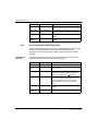
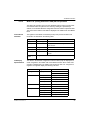
Validity Note
For the Ethernet web embedded server module to work properly, you must have
the proper version of other system components. Use the version specified in the
table below or a later version.
Version
Quantum
Embedded Server
Firmware
Modsoft
Concept
ModLink
1.1
2.6
2.1
2.0
Related Documentation
The following manuals may also be helpful. Be sure to order the version specified
or a later version.
z
z
z
z
z
z
2
Modicon TSX Quantum Automation Series Hardware Reference Guide
840 USE 100 00 Ver. 6
Modicon Ladder Logic Block Library User Guide
840 USE 101 00 Ver. 2
Modicon ModLink User Guide
890 USE 129 00
Modsoft Programmer User Manual
890 USE 115 00
Modbus Protocol Reference Guide
PI-MBUS-300
Web Utility User Manual
890 USE 152 00
840 USE 115 00 Version 1.0
Introduction
1.1
1
Ethernet Web Embedded Server Modules
The Quantum Ethernet Web embedded server modules make it possible for a
Quantum industrial control system to communicate with devices on an Ethernet
network. For example, the modules can be used to link a Quantum Automation
Series controller to a PC.
Each module contains a World Wide Web server, which allows users to obtain
statistics about the NOE module and its controller from an embedded web site.
The Ethernet network is well supported worldwide, with a wide variety of third party
products and services. TCP/IP is the de facto standard protocol.
1.1.1
The Benefits of Quantum Design
Like all Quantum modules, the web embedded server modules are easy to install.
They may be inserted into existing Quantum systems and connected to existing
Ethernet networks. They do not require proprietary cabling.
The modules may be plugged into any slot in a local Quantum backplane and may
be replaced while the system is running (hot swapped). They come fully configured
and are recognized by the controller as soon as they connect with the backplane.
Note: The web embedded server module must be routed through an Ethernet hub
to function properly. Do not connect it directly to another device.
840 USE 115 00 Version 1.0
3
Introduction
1.1.2
Models for Fiber Optic and Twisted Pair Cable Systems
Modicon has designed two Ethernet web embedded server modules: one for fiber
optic networks and the other for networks using twisted pair cabling. Both are
covered in this manual.
Type of Cable Network
4
Part Number
Twisted Pair
140 NOE 211 10
Fiber Optic
140 NOE 251 10
840 USE 115 00 Version 1.0
Introduction
1.2
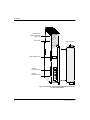
Front Panel Components
On the front panel of each Ethernet embedded web server module, you will find an
LED display, a global address label and a cable connector.
Model Number
Module Description
Color Code
140
NOE 211 10
Ethernet TCP/IP
Active
Ready Fault
Run
Coll
Link
LED Display
Removable Door
Kernel
Global Address Label
Cable Connector
Figure 1 140 NOE 211 10 Ethernet Web Embedded Server
Module for Twisted Pair Networks
840 USE 115 00 Version 1.0
5
Introduction
Model Number
Module Description
Color Code
140
NOE 251 10
Ethernet TCP/IP
Active
Ready Fault
Run
LED Display
Coll
Link
Removable Door
Kernel
Global Address Label
Transmit
Cable Connector
Receive
Cable Connector
Figure 2 140 NOE 251 10 Ethernet Web Embedded Serve Module
for Fiber Optic Networks
6
840 USE 115 00 Version 1.0
Introduction
1.2.1
LED Display
140
NOE 211 10
Ethernet TCP/IP
Active
Ready
Run
Link
Kernel
Figure 3
840 USE 115 00 Version 1.0
Fault
Coll
Appl
LED Display
LED
Color
Indication When On
Active
Green
Module is communicating with backplane.
Ready
Green
Module has passed internal diagnostic tests.
Run
Green
Flashes during normal operation.
Link
Green
Ethernet link to hub is ok.
Kernel
Amber
If steady, module is operating in kernel mode. If
flashing, module is waiting for download.
Fault
Red
An error has been detected, a download has failed or
a reset is in process.
Coll
Red
If steady, cable is not connected.
If flashing, Ethernet collisions are occurring.
Appl
Amber
Entry exists in crash log.
7
Introduction
1.2.2
Address Labels
Each Quantum Ethernet web embedded server module has two address labels.
One identifies the Ethernet or MAC address. The other label allows you to record
the module’s Internet Protocol (IP) network address.
Ethernet
Address Label
The Ethernet address or MAC address is assigned at the factory and is recorded
on a label on the front panel, above the cable connector. This is a unique 48-bit
global assigned address. It is set in PROM. The Ethernet address is recorded on
the label in hexadecimal, in the form 00.00.54.xx.xx.xx.
IEEE GLOBAL ADDRESS
000054xxxxxx
Figure 4
Internet Protocol
(IP) Network
Address Label
Global Address Label
The IP address comes from one of three places in the following order:
z
z
z
The configured address
An address from a BOOTP server
Derived IP network address
You can use the derived address, which is calculated from the Ethernet address
set by the factory. You can also configure a unique address via Modsoft or
Concept. Throughout this book, these alternatives will be referred to as the derived
IP network address and a user-configured address.
The IP network address has the form xxx.xxx.xxx.xxx, where each group xxx is a
decimal number from 0 to 255. A space is provided for recording this address on
the label inside the front door panel of the module.
If you will be operating on an open network, you should opt for a user-configured
address. Obtain a valid address from your network administrator.
If you will be operating on a local network, you may use the derived IP network
address. However, you should check with your network administrator first to ensure
that this address is not already in use.
To calculate the derived IP network address, convert the rightmost eight digits of
the Ethernet address from hex to decimal. They will take the form 84.xxx.xxx.xxx,
where each group xxx is a decimal number from 0 to 255.
8
840 USE 115 00 Version 1.0
Introduction
Example
Calculating the Derived IP Network Address
Locate the global address label on the
front panel of the module.
IEEE GLOBAL ADDRESS
0000540B72A8
Note the rightmost eight digits.
5 4 0 B 7 2 A 8
Convert them from hexadecimal to
decimal. Each pair of hexadecimal
numbers will result in a decimal
number between 0 and 255. This is the
derived IP address.
84.11.114.168
Note: When you have determined which IP network address you will be using,
register it with your system administrator to avoid duplication.
840 USE 115 00 Version 1.0
9
Introduction
1.2.3
Twisted Pair Connector
Pins
8
1
Figure 5
NOE 211 Connector
For the NOE 211, Schneider Automation recommends that you use Category 5
UTP cabling, which is rated to 100 Mbps, with an RJ-45 connector. You may also
use Category 3 UTP cabling, which is rated to 16 Mbps.
The eight pins are arranged vertically and numbered in order from the bottom to the
top. The RJ-45 pinout used by this module is:
z
z
z
z
1.2.4
Receive Data (+)
3
Receive Data (-)
6
Transmit Data (+)
1
Transmit Data (-)
2
Fiber Optic Connectors
Figure 6
NOE 251 Connectors
For the NOE 251, you need 62.5/125 micron fiber optic cable with ST-style
connectors. Schneider Automation offers a 3 m cable with connectors (990 XCA
656 09).
This module comes with two fiber cable clasps, tubular plastic tools for installing
the cable.
10
840 USE 115 00 Version 1.0
Introduction
1.3
Utility Diskette
Included with this manual is a diskette containing two utilities for the Ethernet
module: the Network Options Ethernet Tester utility and the ERRLOG utility.
1.3.1
Network Options Ethernet Tester
This utility will allow you to:
z
z
z
establish a connection
get and clear statistics
read and write registers
The Network Options Ethernet Tester communicates with the module over the
Ethernet, from an IBM-compatible PC operating with Windows 3.1 or greater and
with WinSock.
Instructions for using the Network Options Ethernet Tester are given in Chapter 6
on page 73.
The source code for the Network Options Ethernet Tester is included on the
diskette.
1.3.2
ERRLOG
This utility allows you to read and clear the crash log from an IBM-compatible PC
communicating with the local Quantum controller via Modbus Plus.
The PC must be equipped with an SA85 Modbus Plus card and software driver.
ERRLOG may be run in a native DOS environment or in a DOS box under
Windows 3.1 or Windows 95.
Instructions for using ERRLOG to read and clear the crash log are given in section
7.1.9 on page 85.
840 USE 115 00 Version 1.0
11
Introduction
1.4
Ethernet and Your Application
Careful planning of your network can help you achieve optimum performance. You
should consider whether Ethernet meets the demands of your application, which
devices are compatible with your network and how to minimize congestion on the
network.
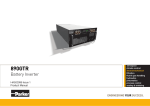
1.4.1
Meeting the Demands of Your Application
The Quantum Ethernet web embedded server modules provide connectivity to
many different systems via an Ethernet network. However, Ethernet installations
have characteristics which may not be suitable for all control applications.
70000
60000
50000
Total
throughput
registers/
second
40000
30000
20000
10000
0
2
3
4
5
10
15
20
Concurrent Nodes
- Ethernet
-Modbus Plus
Note: This data was measured between Quantum controllers on an otherwise empty LAN
and as such reflects best case operation.
Figure 7
12
Network Throughput: Ethernet vs. Modbus Plus
840 USE 115 00 Version 1.0
Introduction
Ethernet network traffic, message length and routing are all variable and can be
unpredictable. This can give rise to congestion and message collisions. When
collisions occur, Ethernet uses a variable delay before retransmitting messages.
Therefore, absolute determinism -- or totally predictable performance -- cannot be
guaranteed on busy Ethernet networks.
1.4.2
Compatibility
Ethernet technology allows devices from different vendors to coexist on the same
network. These devices include hubs, bridges, routers and gateways. However, for
these devices to be compatible they must support the same set of protocols.
Quantum Ethernet modules support Modbus protocol over TCP/IP over Ethernet
protocol. Systems that wish to communicate with Quantum Ethernet web
embedded server modules need to support this protocol stack.
Ethernet
Developers Kit
The Modbus protocol was chosen for its particular suitability for the real time
control environment. It is a well-known and widely-adopted protocol and is fully
described in the Ethernet Developers Kit. This kit (140 EDK 211 00) helps users
develop Ethernet-based communications to their own host (PC-based) sockets
applications. It contains a Quantum Ethernet module plus documentation and
software tools which fully explain the protocols. The Ethernet Developers Kit is
available from your distributor or local Square D office.
Ethernet and
Quantum Hot
Standby
Systems
Ethernet web embedded server modules may be installed in a hot standby system,
but they are not supported at switchover. When control shifts from the primary
controller to the standby, the Ethernet network is not notified. The network
continues to address the Ethernet web embedded server module in the original
primary rack, not the module in the new primary rack.
EMBP Gateway
A Quantum Ethernet web embedded server module can exist on the same Ethernet
network as the EMBP Gateway, but it cannot communicate with the EMBP
Gateway because of differences in formatting and network addressing. However,
the MBT Ethernet Bridge can be used with the web embedded server module (refer
to Modbus Plus to Ethernet Bridge Users Guide, 890 USE 151 00).
1.4.3
Guidelines for Designing Your Network
A typical Ethernet installation carries many different types of traffic. Large data file
transfers or World Wide Web graphics files can keep the network busy and cause
network congestion and collisions. These collisions cause nodes to wait a variable
amount of time before resending their messages. Because the size and frequency
of non-control traffic is unpredictable, network performance may not be suitable for
control applications. These problems can be greatly reduced by segregating the
office and MIS traffic from control data.
840 USE 115 00 Version 1.0
13
Introduction
Segregating
Traffic
The best method to protect Quantum Automation traffic from information systems
traffic is to provide a completely separate physical network for automation control.
Another method is to use readily available Ethernet devices such as bridges and
routers to logically segment the network, isolating office traffic from control data.
Minimizing
Delays
Components such as repeaters, bridges, routers and hubs take a finite time to
process each message. If messages pass through many of these devices,
processing delays will accumulate. Delay times are available from device
manufacturers. Check with your network administrator to quantify the effect on
control messages and to determine whether it will be significant for your
application.
Using Switches
Ethernet switches can be used to ensure higher network performance. These
newer devices allow each connection to have access to the full 10 Mbps bandwith
instead of having to share the bandwith with all other nodes. They reduce the
timing problems associated with Ethernet collisions and the resulting “back off”
transmission delays. Check with your network administrator to see if your
application would benefit from switching Ethernet devices.
14
840 USE 115 00 Version 1.0
Installing and Configuring the
Module
2.1
2
Before You Begin . . .
Quantum Ethernet web embedded server modules come fully configured. They are
designed to go straight from the box to the backplane. But before you install your
module, you must verify that:
z
z
the default configuration is appropriate for your network
your Ethernet network is properly constructed
CAUTION
DUPLICATE ADDRESS HAZARD
The default configuration includes the IP network address. Do not connect this module to
your network until you have ensured that its IP address will be unique on the network.
Failure to observe this precaution can result in injury or equipment damage.
2.1.1
Verifying the Default Configuration
You should change the default configuration before installing the module:
z
z
z
z
840 USE 115 00 Version 1.0
if the module will be communicating on an open network
if the module’s derived IP network address is already in use on your network
if the network uses IEEE 802.3 framing
if you need to specify the default Ethernet gateway and subnet mask
15
Installing and Configuring the Module
Consult your network administrator to see if any of these conditions apply. If they
do, follow the directions on page 20 for changing the default configuration.
Note: If you will be changing the default configuration, you should stop the
controller, then install the module, then change the configuration before starting the
controller again.
The Ethernet web embedded server module only reads its configuration data at
power-up and when it is reset. Whenever the configuration data is changed, the
module must be reset, either by hot swapping or through a reset command in the
MSTR block (see page 37). Once the module is installed, stopping and restarting
the controller will not reset it.
2.1.2
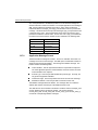
Verifying that the Network Has Been Constructed Properly
You should not connect an Ethernet web embedded server module directly to
another device with a length of cable. For the network to operate properly, you
must route the cable for each device through an Ethernet hub. Hubs are widely
available and can be purchased from many suppliers.
NOE
Figure 8
NOE
NOE
Improper Network Topologies
NOE
NOE
Hub
Figure 9
16
Proper Network Topology
840 USE 115 00 Version 1.0
Installing and Configuring the Module
2.2
Installing the Module
The Ethernet web embedded server module comes fully ready to be installed.
Installation consists of mounting the module on the backplane and connecting the
cable.
2.2.1
Are You Really Ready to Install? Check!
Have you reviewed the configuration and network guidelines on page 15? You
must meet those guidelines before installing the module. If you are planning to
change the default configuration, stop the controller before installing the Ethernet
web embedded server module.
Modicon also recommends that you test to be sure your Ethernet cabling is working
properly before connecting it to the Ethernet module. Some suppliers of testing
equipment are listed in Appendix D.
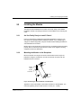
2.2.2
Mounting the Module on the Backplane
Mount the module at an angle onto the two hooks located near the top of the
backplane. Swing the module down to make an electrical connection with the
backplane I/O bus connector.
Module
Hooks
I/O Bus
Connector
Figure 10 Mounting an Ethernet Module on the Backplane
Tighten the screw at the bottom of the module to fasten it to the backplane. The
maximum tightening torque for this screw is 2-4 in-lbs (.23 - .45 Nm).
840 USE 115 00 Version 1.0
17
Installing and Configuring the Module
2.2.3
Connecting the Cable
Twisted Pair
If you are using twisted pair cable, Modicon recommends Category 5, which is
rated to 100 Mbps. Use RJ-45 connectors. Slip the connector into the port. It should
snap into place.
Fiber Optic
Use 62.5/125 fiber optic cable with ST-style connectors. Modicon sells a 3 m cable
with connectors (990 XCA 656 09).
Remove the protective plastic coverings from the cable ports and the tips of the
cable. Snap one of the fiber cable clasps onto the cable, carefully pressing the
cable through the slot so that the wider end of the clasp is closest to the boot.
Cable Boot
Fiber Cable Clasp
Figure 11 Attaching the Fiber Cable Clasp to the Cable
The key to installing the cable is to align the barrel, the locking ring and the
connector.
Key
Arrow
Lock
Barrel
Groove
Locking Ring
Figure 12 Aligning the Key and Locking Ring
18
840 USE 115 00 Version 1.0
Installing and Configuring the Module
Turn the locking ring to align an arrow with the key. Then align the key with the
keyway. As a result, the locking tab, groove and lock should also be aligned.
Slide the clasp up to the locking ring. Gripping the cable with the clasp, plug the
cable into the lower (receive) cable connector. If it does not connect easily, realign
the key with the arrow and try again.
Connector
Locking Tab
Keyway
Locking Ring
Key
Fiber Cable Clasp
Figure 13 Attaching the Cable
Turn the cable to the right, so that the tab locks securely. You may leave the fiber
cable clasp on the cable for future use, but slide it off the boot of the cable to allow
the module door to close.
Repeat this process with the remaining strand of cable and the upper (transmit)
cable connector.
When connecting the cable to the hub, make sure that the strands are crossed. The
transmit port of one device should be linked to the receive port of the other.
840 USE 115 00 Version 1.0
19
Installing and Configuring the Module
2.3
Changing the Default Configuration
If any of the following conditions apply, you should stop the controller, then install
the module, then change the default configuration before starting the controller
again:
z
z
z
z
The module will be communicating on an open Ethernet network.
The module’s IP address is already in use.
The network uses IEEE 802.3 framing.
You must specify a default Ethernet gateway and subnet mask.
If you change the configuration after installing the module, you must reset the
module for your changes to take effect.
You may configure the module using Modsoft or Concept.
2.4
Configuring the Module with Modsoft
From the Modsoft Configuration Overview screen, select the Cfg Ext pulldown
menu.
Be sure that you have specified sufficient memory resources for the Ethernet
configuration extension in the Cfg. Extension Size field. The first Ethernet module
configured requires 20 words. Each additional module requires an additional 16
words.
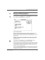
From the options, select TCP/IP Setup. You will reach the Ethernet configuration
extension screen.
20
840 USE 115 00 Version 1.0
Installing and Configuring the Module
modsoft
Dec
F2
Goto
F4
F5
F6
Quantum TCP/IP CONFIG EXT.
Ethernet Framing Type: Ethernet II
Hex
F1
Bin
F3
Quantum Backplane Slot: 0
Internet Address:
(B4) :
(B3) :
(B2) :
(B1) :
0
0
0
0
Lev 8 F8
Quit
OFF F9
Screen 1 / 6
B4. B3. B2. B1
Note: 000.000.000.000
represents the TCP/IP
Board Default
Internet Address
DEC
DEC
DEC
DEC
Default Gateway Address:
(G4) : 0
DEC
(G3) : 0
DEC
(G2) : 0
DEC
(G1) : 0
DEC
SubNetwork MASK: FFFFFF00
F7
G4. G3. G2. G1
Note: 000.000.000.000
represents the TCP/IP
Board Default
Gateway Address
HEX
PgDn/Up to next/prev Screen
Figure 14 Configuration Extension Screen
2.4.1
Selecting the Ethernet Framing Type
You may choose between Ethernet II and IEEE 802.3, depending on your system.
The default choice is Ethernet II.
If you are using the configuration extension to change the framing to IEEE 802.3,
do not forget to designate the backplane slot number on the next line. Without the
slot number, the system will not record the change in framing.
2.4.2
Assigning a Slot Number
To activate the configuration extension screen, you must enter the backplane slot
number on the second line. This is the slot where you have mounted or intend to
mount the Ethernet web embedded serve module. The slots are numbered from left
to right, from one to x.
Note: If you do not enter the slot number, the system will ignore any other data
you enter on this screen.
840 USE 115 00 Version 1.0
21
Installing and Configuring the Module
2.4.3
Assigning the IP Network Address
The Internet Protocol (IP) network address is a 32-bit address in the form
xxx.xxx.xxx.xxx, where each group xxx is a decimal number ranging from 0 to 255.
If the module will be communicating on an open network or if the module’s derived
IP address is already being used, consult your network administrator to obtain a
unique address. Type the new address in fields B4 through B1.
A space is provided for recording the IP network address on the label inside the
front door panel.
If you input the address before installing the module or if you hot swap the module,
it will automatically recognize the address you have already specified and will
identify itself accordingly.
CAUTION
DUPLICATE ADDRESS HAZARD
Be sure to register the module’s IP network address with your system administrator to avoid
duplication.
Failure to observe this precaution can result in injury or equipment damage.
Note: If you are using the configuration extension to change the IP network
address, you also must input the backplane slot number. Without the slot number,
the system will not recognize your changes.
2.4.4
Assigning the Default Gateway Address and Subnet Mask
Consult your network administrator to determine whether you need to specify a
default gateway address and subnet mask. If this data is required, the network
administrator should supply it. Input the gateway address in fields G4 through G1.
Input the subnet mask at the bottom of the screen.
Note: If you are using the configuration extension to assign a gateway address
and subnet mask, remember to input a slot number as well. The slot number is
required to activate the configuration extension.
2.4.5
Resetting the Module
If you change the default configuration after installing the module, you must reset
the module for your changes to take effect. The module may be reset through a
command in the MSTR block in Modsoft(page 37), by cycling power or by lifting the
module off the backplane and then setting it back in its slot.
22
840 USE 115 00 Version 1.0
Installing and Configuring the Module
2.4.6
Configuring More Than One Ethernet Module
You may configure from two to six Ethernet modules in a single controller,
depending on the model. A 140 CPU 113 or 213 will accept a total of two network
option modules, including NOE, NOM, NOP, CRP 811and other modules. A 140
CPU 424, 434 or 534 will accept six.
The first Ethernet web embedded server module configured requires 20 words of
memory. Each additional module requires an additional 16 words of memory.
The modules may be placed in any slot in the backplane. They do not have to be
placed next to each other.
To configure the modules, simply page down to an unused configuration extension
screen. Enter the backplane slot number to activate the screen.
840 USE 115 00 Version 1.0
23
Installing and Configuring the Module
2.5
Configuring the Module with Concept
Once the Ethernet web embedded server module has been installed in the
backplane and you have consulted your network administrator about whether to
change the IP address or framing or to specify a gateway or subnet mask:
1.
Open the Concept project without connecting to the controller. The controller
and I/O should be configured.
2.
Set the number of Ethernet modules in the configuration extension.
3.
Enter each Ethernet module in the I/O map.
4.
Fill in the parameter dialog box for each Ethernet module.
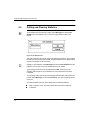
Figure 15 Parameter Dialog for an Ethernet Web Embedded Server Module
5.
Save the project.
6.
Connect to the controller.
7.
Open the online control panel. Clear the existing configuration of the controller.
8.
Download the project, including the configuration, to the controller. Do not start
the controller. Leave the dialog open.
9.
Reset the Ethernet web embedded server module in the backplane (hot swap).
Wait until the Link indicator lights.
10. Start the controller. This will close the dialog box.
24
840 USE 115 00 Version 1.0
The MSTR Instruction
3.1
3
Introduction
All NOE 2X1 10 Quantum Ethernet web embedded server modules provide the
user with the capability of transferring data to and from nodes on a Modbus Plus or
TCP/IP network through the use of a special MSTR (master instruction). All PLCs
that support networking communication capabilities over Modbus Plus and
Ethernet can use the MSTR ladder logic instruction to read or write controller
information.
3.2
MSTR Description
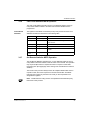
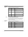
The MSTR instruction allows you to initiate one of 12 possible network
communications operations over the network. Each operation is designated by a
code. The following table lists the 12 operations and indicates those that are
supported on an Ethernet TCP/IP network.
840 USE 115 00 Version 1.0
MSTR Operation
Code
TCP/IP Ethernet Support
Write data
1
supported
Read Data
2
supported
Get local statistics
3
supported
Clear local statistics
4
supported
25
The MSTR Instruction
MSTR Operation
Code
TCP/IP Ethernet Support
Write global database
5
not supported
Read global database
6
not supported
Get remote statistics
7
supported
Clear remote statistics
8
supported
Peer Cop health
9
supported
Reset Option Module
10
supported
Read CTE(config extension)
11
supported
Write CTE (config extension)
12
supported
Up to four MSTR instructions can be simultaneously active in a ladder logic
program. More than four MSTRs may be programmed to be enabled by the logic
flow as one active MSTR block releases the resources it has been using and
becomes deactivated, the next MSTR operation encountered in logic can be
activated.
3.2.1
Size
PLC
Compatibility
Characteristics
Three nodes high
z
z
z
Opcode
26
Standard in PLCs that have built-in Modbus Plus capabilities (Modbus Plus
functionality only)
Standard in all Quantum PLCs with Modbus Plus functionality and/or TCP/IP
Ethernet option modules
Available as a loadable in chassis mount PLCs (Modbus Plus functionality
only)
BF hex
840 USE 115 00 Version 1.0
The MSTR Instruction
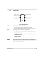
3.2.2
Representation
Enables selected
MSTR operation
control
block
Terminates active
MSTR operation
data
area
Operation terminated
unsuccessfully
MSTR
length
Operation successful
Operation is active
Figure 16 MSTR Block Structure
Inputs
The MSTR instruction has two control inputs:
z
z
Outputs
z
z
z
840 USE 115 00 Version 1.0
the input to the middle node terminates the active operation when it is ON
The MSTR instruction can produce three possible outputs:
z
Top Node
Content
the input to the top node enables the instruction when it is ON
the output from the top node echoes the state of the top input - it goes ON
while the instruction is active
the output from the middle node echoes the state of the middle input - it goes
ON if the MSTR operation is terminated prior to completion or if an error occurs
in completing the operation
the output from the bottom node goes ON when an MSTR operation has been
completed successfully
all outputs are zero indicates four MSTR instructions are already in progress
The 4x register entered in the top node is the first of several (network dependent)
holding registers that comprise the network control block. The control block
structure differs according to the network in use. For the TCP/IP Ethernet network
the control block structure is as follows:
27
The MSTR Instruction
Middle Node
Content
Register
Content
Displayed
Identifies one of ten MSTR operations legal for TCP/IP
(1 ... 4 and 7 ... 12).
First implied
Displays error status.
Second implied
Displays length (number of registers transferred).
Third implied
Displays MSTR operation-dependent information.
Fourth implied
High byte: Destination index.
Low byte: Quantum backplane slot address of the web
embedded server module.
Fifth implied
Byte 4 of the 32-bit destination IP Address.
Sixth implied
Byte 3 of the 32-bit destination IP Address.
Seventh implied
Byte 2 of the 32-bit destination IP Address.
Eight implied
Byte 1 of the 32-bit destination IP Address.
The 4x register entered in the middle node is the first in a group of contiguous
holding registers that comprise the data area. For operations that provide the
communication processor with data such as a Write operation, the data area is the
source of the data. For operations that acquire data from the communication
processor, such as a Read operation, the data area is the destination for the data.
In the case of the Ethernet Read and Write CTE operations (see sections 3.2.11
and 3.2.12), the middle node stores the contents of the Ethernet configuration
extension table in a series of registers.
Bottom Node
Content
3.2.3
The integer value entered in the bottom node specifies the length - the maximum
number of registers in the data area. The length must be in the range 1 ... 100.
MSTR Function Error Codes
If an error occurs during an MSTR operation, a hexadecimal error code will be
displayed in the first implied register in the control block (the top node). Function
error codes are network-specific.
TCP/IP Ethernet
Error Codes
28
An error in an MSTR routine over TCP/IP Ethernet may produce one of the
following errors in the MSTR control block:
840 USE 115 00 Version 1.0
The MSTR Instruction
Hex Error Code Meaning
1001
User has aborted the MSTR element.
2001
An unsupported operation type has been specified in the control block.
2002
One or more control block parameters has been changed while the
MSTR element is active (applies only to operations that take multiple
scans to complete). Control block parameters may be changed only
when the MSTR element is not active.
2003
Invalid value in the length field of the control block.
2004
Invalid value in the offset field of the control block.
2005
Invalid values in the length and offset fields of the control block.
2006
Invalid slave device data area.
3000
Generic Modbus fail code.
30ss*
Modbus slave exception response.
4001
Inconsistent Modbus slave response.
F001
Option Module not responding
* The ss subfield in error code 30ss is shown in the following table.
ss Hex value
Meaning
01
Slave device does not support the requested operation.
02
Nonexistent slave device registers requested.
03
Invalid data value requested.
04
05
Slave has accepted long-duration program command.
06
Function can’t be performed now; a long-duration command is
in effect.
07
Slave rejected long-duration program command.
An error on the TCP/IP Ethernet network itself may produce one of the following
errors in the MSTR control block:
840 USE 115 00 Version 1.0
Hex Error Code
Meaning
5004
Interrupted system call.
5005
I/O error.
5006
No such address.
5009
The socket descriptor is invalid.
500C
Not enough memory.
500D
Permission denied.
5011
Entry exists.
29
The MSTR Instruction
30
Hex Error Code
Meaning
5016
An argument is valid
5017
An internal table has run out of space.
5020
The connection is broken.
5023
This operation would block and the socket is nonblocking.
5024
The socket is nonblocking and the connection cannot be completed.
5025
The socket is nonblocking and a previous connection attempt has not yet
completed.
5026
socket opreation on a nonsocket.
5027
The destination address is invalid.
5028
Message too long.
5029
Protocol wrong type for socket.
502A
Protocol not available.
502B
Protocol not supported.
502C
Socket type not supported.
502D
Operation not supported on socket.
502E
Protocol family not supported.
502F
Address family not supported.
5030
Address is already in use.
5031
Address is not available.
5032
Network is down.
5033
Network is unreachable.
5034
Network dropped connection on reset.
5035
The connection has been aborted by the peer.
5036
The connection has been reset by the peer.
5037
An internal buffer is required, but cannot be allocated.
5038
The socket is already connected.
5039
The socket is not connected.
503A
Can’t send after socket shutdown.
503B
Too many references; can’t splice.
503C
connection timed out.
503D
The attempt to connect was refused.
5040
Host is down.
5041
The destination host could not be reached from this node.
5042
Directory not empty.
5046
NI_INIT returned
840 USE 115 00 Version 1.0
The MSTR Instruction
CTE Error Codes
3.2.4
Hex Error Code
Meaning
5047
The MTU is invalid
5048
The hardware length is invalid.
5049
The route specified cannot be found.
504A
Collision in select call: these conditions have already been selected by
another task.
504B
The task id is invalid.
The following error codes are returned if there is a problem with the Ethernet
configuration extension table (CTE) in your program configuration.
Hex Error Code
Meaning
7001
There is no Ethernet configuration extension.
7002
The CTE is not available for access.
7003
The offset is invalid.
7004
The offset + length is invalid.
7005
Bad data field in the CTE.
Read and Write MSTR Operations
An MSTR Write operation (type 1 in the displayed register of the top node)
transfers data from a master source device to a specified slave destination device
on the network. An MSTR Read operation (type 2 in the displayed register of the
top node) transfers data from a specified slave source device to a master
destination device on the network. Read and Write use one data master transaction
path and may be completed over multiple scans.
Note: TCP/IP Ethernet routing must be accomplished via standard third-party
Ethernet IP router products.
Control Block
Utilization
The registers in the MSTR control block (the top node) contain the Read or Write
information as described in the following table:
Register
Function
Content
Displayed
Operation Type
1 = Write, 2 = Read.
First Implied
Error status
Displays a hex value indicating an MSTR error.
Exception response, where Exception code
response size is incorrect. + 3000
Exception response where
response size is incorrect.
4001
Read Write
840 USE 115 00 Version 1.0
31
The MSTR Instruction
3.2.5
Register
Function
Content
Second implied
Length
Write = number of registers to be sent to slave.
Read = number of registers to be read from slave.
Third implied
Slave device data
area
Specifies starting 4x register in the slave to be
read from or written to (1 = 4001, 49 =40049).
Fourth implied
Low byte
Quantum backplane slot address of the NOE
module.
Fifth ... eighth
implied
Destination
Each register contains one byte of the 32-bit IP
address.
Get Local Statistics MSTR Operation
The Get Local Statistics operation (type 3 in the display register of the top node)
obtains information related to the local node where the MSTR has been
programmed. (See page page 40 for a listing of the TCP/IP Ethernet network
statistics).
Control Block
Utilization
32
The registers in the MSTR control block (the top node) contain the Get Local
Statistics information as described in the following table:
Register
Function
Content
Displayed
Operation Type
3
First implied
Error status
Displays a hex value indicating an MSTR error,
when relevant.
Second implied Length
Starting from offset, the number of words of
statistics from the local processor’s statistics
table; the length must be > 0 < data area.
Third implied
Offset
An offset value relative to the first available word
in the local processor’s statistics table. If the
offset is specified as 1, the function obtains
statistics starting with the second word in the
table.
Fourth implied
Low byte
Quantum backplane slot address of the NOE
module.
Fifth .. Eighth
implied
Not applicable
840 USE 115 00 Version 1.0
The MSTR Instruction
3.2.6
Clear Local Statistics MSTR Operation
The Clear Local Statistics operation (type 4 in the displayed register of the top
node) clears statistics relative to the local node where the MSTR has been
programmed.
Control Block
Utilization
The registers in the MSTR control block (the top node) contain the Clear Local
Statistics information as described in the following table:
Register
Function
Content
Displayed
Operation Type
4
First implied
Error status
Displays a hex value indicating an MSTR error,
when relevant.
Second implied Not applicable
3.2.7
Third implied
Not applicable
Fourth implied
Low byte
Fifth ... Eighth
implied
Not applicable
Quantum backplane slot address of the NOE
module.
Get Remote Statistics MSTR Operation
The Get Remote Statistics operation (type 7 in the displayed register of the top
node) obtains information relative to remote nodes on the network. This operation
may require multiple scans to complete and does not require a master data
transaction path. (See page page 40 for a listing of the TCP/IP Ethernet network
statistics).
The remote comm processor always returns its complete statistics table when a
request is made, even if the request is for less than the full table. The MSTR
instruction then copies only the amount of words you have requested to the
designated 4x registers.
Note: TCP/IP Ethernet routing must be accomplished via standard third-party
Ethernet IP router products.
840 USE 115 00 Version 1.0
33
The MSTR Instruction
Control Block
Utilization
The registers in the MSTR control block (the top node) contain the Get Remote
Statistics information as described in the following table:
Register
3.2.8
Function
Content
Displayed
Operation Type
7
First implied
Error status
Displays a hex value indicating an MSTR error,
when relevant.
Second implied Length
Starting from an offset, the number of words of
statistics from the local processor’s statistics
table. The length must be > 0 < data area.
Third implied
Offset
Specifies an offset value relative to the first
available word in the local processor’s statistics
table. If the offset is specified as 1, the function
obtains statistics starting with the second word in
the table.
Fourth implied
High byte
Destination index.
Fifth ... Eighth
implied
Destination
Each register contains one byte of the 32-bit IP
address.
Clear Remote Statistics MSTR Operation
The Clear Remote Statistics operation (type 8 in the displayed register of the top
node) clears statistics relative to a remote network node from the data area in the
local node. This operation may require multiple scans to complete and uses a
single data master transaction path.
Control Block
Utilization
The registers in the MSTR control block (the top node) contain the Clear Remote
Statistics information as described in the following table:
Register
Function
Content
Displayed
Operation Type
8
First implied
Error status
Displays a hex value indicating an MSTR error,
when relevant.
Second implied Not applicable
34
Third implied
Not applicable
Fourth implied
High byte
Destination index.
Fifth ... Eighth
implied
Destination
Each register contains one byte of the 32-bit IP
address.
840 USE 115 00 Version 1.0
The MSTR Instruction
3.2.9
Peer Cop Health MSTR Operation
The peer cop health operation (type 9 in the displayed register of the top node)
reads selected data from the peer cop communications health table and loads that
data to specified 4x registers in state RAM. The peer cop communications health
table is12 words long, and the words are indexed via this MSTR operation as words
0 ... 11.
Control Block
Utilization
Peer Cop
Communications
Health Status
Information
The registers in the MSTR control block (the top node) contain the information for a
Peer Cop Health operation as described in the following table:
Register
Function
Content
Displayed
Operation Type
9
First implied
Error status
Displays a hex value indicating an MSTR error,
when relevant.
Second implied Data Size
Number of words requested from peer cop table
(range 1 ... 12).
Third implied
Index
First word from the table to be read (range 0 ...
11, where 0 = the first word in the peer cop table
and 11 = the last word in the table).
Fourth implied
Low byte
Quantum backplane slot address of the NOE
module.
Fifth ... Eighth
implied
Destination
Each register contains one byte of the 32-bit IP
address.
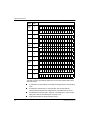
The peer cop communications health table (shown below) comprises 12
contiguous register that can be indexed in an MSTR operation as words 0 ... 11.
Each bit in each of the table words is used to represent an aspect of
communications health relative to a specific node on the TCP/IP network:
z
z
z
840 USE 115 00 Version 1.0
The bits in words 0 ... 3 represent the health of the global input communication
expected from nodes 1 ... 64. Since global input is not supported these bits are
set to zero.
The bits in words 4 ... 7 represent the health of the output from a specific node.
The bits in words 8 ... 11 represent the health of the input to a specific node.
35
The MSTR Instruction
Type of Word
Status Index
Global
Input
Specific
Output
Specific
Input
Bit-To-Network Node Relationship
0
0
0
0
0
0
0
0
0 0
1
0
0
0
0
0
0
0
0
2
0
0
0
0
0
0
0
3
0
0
0
0
0
0
0
0 0 0
0
0
0
0 0
0
0 0
0
0
0
0 0
0
0
0
0 0
0
0
0
0 0
0 0 0
0
0
2
1
0
0
4
16 15 14 13 12 11 10 9 8
7
5
32 31 30 29 28 27 26 25 24 23 22 21 20 19 18 17
6
48 47 46 45 44 43 42 41 40 39 38 37 36 35 34 33
7
64 63 62 61 60 59 58 57 56 55 54 53 52 51 50 49
8
16 15 14 13 12 11 10 9 8
9
32 31 30 29 28 27 26 25 24 23 22 21 20 19 18 17
10
48 47 46 45 44 43 42 41 40 39 38 37 36 35 34 33
11
64 63 62 61 60 59 58 57 56 55 54 53 52 51 50 49
7
6 5 4
6 5 4
3
3
2
1
The state of a peer cop health bit reflects the current communication status of its
associated node:
z
z
z
z
36
A health bit is set when data is successfully exchanged with its corresponding
node.
A health bit is cleared when no communication has occurred with the
corresponding node within the configured peer cop health time-out period.
All health bits are cleared at PLC start time. The health bit for a given node is
always zero when its associated peer cop entry is null.
All global health bits are always reported as zero.
840 USE 115 00 Version 1.0
The MSTR Instruction
3.2.10
Reset Option Module MSTR Operation
The Reset Option Module operation (type 10 in the displayed register of the top
node) causes a Quantum web embedded server module to enter a reset cycle to
reset its operational environment.
Control Block
Utilization
The registers in the MSTR control block (the top node) contain the Reset Option
Module information as described in the following table:
Register
Function
Content
Displayed
Operation Type
10
First implied
Error status
Displays a hex value indicating an MSTR error,
when relevant.
Second implied Not applicable
3.2.11
Third implied
Not applicable
Fourth implied
Low byte
Fifth ... Eighth
implied
Not applicable
Quantum backplane slot address of the web
embedded server module.
Read CTE (Config Extension Table) MSTR Operation
The Read CTE operation (type 11 in the displayed register of the top node) reads a
given number of bytes from the Ethernet configuration extension table to the
indicated buffer in PLC memory. The bytes to be read begin at a byte offset from
the beginning of the CTE. The content of the Ethernet CTE table is displayed in the
middle node of the MSTR block.
840 USE 115 00 Version 1.0
37
The MSTR Instruction
Control Block
Utilization
The registers in the MSTR control block (the top node) contain the Read CTE
information as described in the following table:
Register
Function
Content
Displayed
Operation Type
11
First implied
Error status
Displays a hex value indicating an MSTR error,
when relevant.
Second implied Not applicable
CTE Display
Implementation
Third implied
Not applicable
Fourth implied
Low byte
Fifth ... Eight
implied
Not applicable
Quantum backplane slot address of the web
embedded server module.
The values in the Ethernet configuration extension table (CTE) are displayed in a
series of registers in the middle node of the MSTR instruction when a Read CTE
operation is implemented. The middle node contains the first of 11 contiguous 4x
registers. The registers display the following CTE data:
Parameter
Register
Content
Frame type
Displayed
1 = 802.3
IP Address
First implied
2 = Ethernet
38
First byte of the IP address
Second implied
Second byte of the IP address
Third implied
Third byte of the IP address
Fourth implied
Fourth byte of the IP address
Subnetwork mask
Fifth implied
Hi word
Sixth implied
Low word
Gateway
Seventh implied
First byte of the gateway
Eighth implied
Second byte of the gateway
Ninth implied
Third byte of the gateway
Tenth implied
Fourth byte of the gateway
840 USE 115 00 Version 1.0
The MSTR Instruction
3.2.12
Write CTE (Config Extension Table) MSTR Operation
The Write CTE operation (type 12 in the displayed register of the top node) reads
an indicated number of bytes from PLC memory, starting at a specified byte
address, to an indicated Ethernet configuration extension table at a specified offset.
The content of the Ethernet CTE table is displayed in the middle node of the MSTR
block.
Control Block
Utilization
The registers in the MSTR control block (the top node) contain the Write CTE
information as described in the following table:
Register
Function
Content
Displayed
Operation Type
12
First implied
Error status
Displays a hex value indicating an MSTR error,
when relevant.
Second implied Not applicable
CTE Display
Implementation
Third implied
Not applicable
Fourth implied
Low byte
Fifth ... Eight
implied
Not applicable
Quantum backplane slot address of the NOE
module.
The values in the Ethernet configuration extension table (CTE) are displayed in a
series of registers in the middle node of the MSTR instruction when a Write CTE
operation is implemented. The middle node contains the first of 11 contiguous 4x
registers. The registers display the following CTE data:
Parameter
Register
Frame type
Displayed
Content
1 = 802.3
2 = Ethernet
IP Address
Subnetwork mask
Gateway
840 USE 115 00 Version 1.0
First implied
First byte of the IP address
Second implied
Second byte of the IP address
Third implied
Third byte of the IP address
Fourth implied
Fourth byte of the IP address
Fifth implied
Hi word
Sixth implied
Low word
Seventh implied
First byte of the gateway
Eighth implied
Second byte of the gateway
Ninth implied
Third byte of the gateway
Tenth implied
Fourth byte of the gateway
39
The MSTR Instruction
3.2.13
TCP/IP Ethernet Statistics
A TCP/IP Ethernet board responds to “Get Local Statistics” and “Set Local
Statistics” commands with the following information:
40
Word
Meaning
00 ... 02
MAC address
03
Board Status
04 and 05
Number of receiver interrupts
06 and 07
Number of transmitter interrupts
08 and 09
Transmit _ timeout error count
10 and 11
Collision_detect error count
12 and 13
Missed packets
14 and 15
Memory error
16 and 17
Number of times driver has restarted lance
18 and 19
Receive framing error
20 and 21
Receiver overflow error
22 and 23
Receive CRC error
24 and 25
Receive buffer error
26 and 27
Transmit silo underflow
28 and 29
Late collision
30 and 31
Lost carrier
32 and 33
Number of retries
34 and 35
IP address
840 USE 115 00 Version 1.0
Retrieving Data via the World
Wide Web
4.1
4
Introduction
Each Ethernet web embedded server module contains a World Wide Web server.
Pages on the embedded web site display:
z
z
z
z
z
z
the Ethernet statistics for the node
the controller’s configuration
the controller’s register values
the controller’s configuration
the status, configuration and register values of remote I/O
the status, configuration and register values of distributed I/O
The web pages can only be viewed across the World Wide Web using either
Netscape Navigator version 4.06 (or higher), or Internet Explorer version 4.0 w/
SP1(or higher), both of which support JDK 1.1.6 (or higher).
840 USE 115 00 Version 1.0
41
Retrieving Data via the World Wide Web
4.2
Accessing the Web Utility Home Page
Before you can access the module’s home page, you must learn its full IP address
or URL from your system administrator. Type the address or URL in the Address or
Location box in the browser window which will then bring Schneider’s web utility
home page onto the screen. (See Figure 17.)
Figure 17 Web Utility Home Page
Select “Diagnostics and Online Data Editor” from the web utility home page to bring
the Quantum Web utility page onto the screen. (See Figure 18.)
42
840 USE 115 00 Version 1.0
Retrieving Data via the World Wide Web
Figure 18 Quantum Web Utility Page
4.3
Web Utility for Quantum Page
The Quantum web utility page contains hyperlinks to seven pages of data:
z
z
z
z
z
z
z
Configured Local Rack
Controller Status
Ethernet Statistics
RIO Status
Configured RIO
Configured DIO
Data Editor
These pages are discussed in detail in the Web Utility Users Manual for Quantum &
Premium PLCs, 890 USE 152 00.
840 USE 115 00 Version 1.0
43
Retrieving Data via the World Wide Web
44
840 USE 115 00 Version 1.0
Using the Network Options
Ethernet Tester
5.1
5
Introduction
An Ethernet module may act as a client or as a server.
If it will be acting as a client -- that is, initiating transactions on the network for its
Quantum controller -- then you must program an MSTR block in ladder logic.
For details about the MSTR block, please refer to Chapter 3 on page 25.
The Ethernet module may also act as a server, responding to requests and
commands from devices on the network for its Quantum controller.
The Network Options Ethernet Tester utility allows you to get and clear statistics
and to read and write registers over the network, using a Windows-based PC.
You may also create your own program using the Ethernet module as a server. For
guidance in creating your own program, refer to Appendix B on page 65.
Note: In its capacity as server, the Ethernet module can only accept 20
connections at any one time. If a new connection is attempted and the server has
already reached its limit, it will terminate the least used connection in order to make
room for the new one.
840 USE 115 00 Version 1.0
45
Using the Network Options Ethernet Tester
5.2
Installing the Network Options Ethernet Tester
Insert the utility diskette in your disk drive. Run A:\Setup.exe.
5.3
Establishing a Connection with an Ethernet
Module
To establish a connection with an Ethernet module using the Network Options
Ethernet Tester, you must know the module’s IP network address or host name.
Clear statistics
Get statistics
Write register
Read register
Disconnect
Connect
Create new connection
Figure 19 Initial Menu
From the initial menu, select File and choose New from the options in the pulldown
menu or click on the new connection button in the toolbar.
46
840 USE 115 00 Version 1.0
Using the Network Options Ethernet Tester
Type the module’s IP network address or host name in the box provided. Click the
OK button. This dedicates a connection from your PC to the designated Ethernet
module and brings you to the main menu.
(module address)
(module address)
(module address)
Figure 20 Main Menu
To activate the connection, select Management and choose Connect from the
pulldown menu or click on the connect button in the toolbar.
When you are ready to disconnect, select Management and choose Disconnect
from the pulldown menu or click on the disconnect button in the toolbar.
You may establish several connections with the same module or with other
modules by selecting New from the File pulldown menu or by clicking on the create
new connection button in the toolbar. Each connection has its own window within
the main window. The Window pulldown menu gives you options for arranging
connection windows and allows you to select one. The options available on the
pulldown menus and toolbar in the main window apply to the selected connection.
After disconnecting from one module, you may reassign its dedicated connection
by selecting Management and choosing Set IP Address from the pulldown menu.
Type the new IP network address or host name in the box provided.
840 USE 115 00 Version 1.0
47
Using the Network Options Ethernet Tester
5.4
Getting and Clearing Statistics
To get statistics from the Ethernet module, select Messages and choose Get
Statistics from the pulldown menu or click on the get statistics button in the
toolbar.
Figure 21 Get Statistics Box
The polling interval is the number of seconds between transactions. Type a polling
interval in the box provided and click OK. Complete statistics for the module will be
printed in the window for this connection.
Similarly, to clear statistics, select Messages and choose Clear Statistics from the
pulldown menu or click on the clear statistics button in the toolbar.
Type a polling interval in the box provided and click OK. The first line in the
statistics, total transaction count, indicates how many transactions have been
completed.
To change the polling interval without interrupting communication with the Ethernet
module, select Messages and choose Poll Interval. Type the new polling interval
in the box.
The Network Options Ethernet Tester will provide the following statistics:
z
z
48
Total Transaction Count. How many transactions have been completed.
IP Address.
840 USE 115 00 Version 1.0
Using the Network Options Ethernet Tester
z
MAC Address.
Figure 22 Sample Statistics
z
Status. The hex value displayed may be 0001, 8001 or C001:
840 USE 115 00 Version 1.0
0001 indicates that the module is running, the Link indicator is not lit and
no entry exists in the crash log
8001 indicates that module is running and the Link indicator is lit. No entry
exists in the crash log.
C001 indicates that the module is running, the Link indicator is lit and an
entry exists in the crash log.
49
Using the Network Options Ethernet Tester
z
z
z
z
z
z
z
z
z
z
z
z
z
z
z
Receive Interrupts and Transmit Interrupts. The number of times the PCNET
controller chip has generated interrupts.
Transmit timeout errors. The number of times the transmitter has been on the
channel longer than the interval required to send the maximum length frame of
1519 bytes. This is also known as a babble error.
Collision errors. The number of collisions detected by the Ethernet chip.
Missed packet errors. The number of times a received frame was dropped
because a receive descriptor was not available.
Memory errors. The number of times an Ethernet controller chip experienced
an error accessing shared RAM. A memory error will cause a restart.
PcNet restart count. The number of times the Ethernet controller chip was
restarted due to fatal runtime errors, including memory errors, transmit buffer
errors and transmit underflow.
Framing error. The number of times an incoming frame contained a noninteger multiple of eight bits.
Overflow errors. The number of times the receiver has lost part or all of an
incoming frame, due to an inability to store the frame in memory before the
internal FIFO overflowed.
CRC errors. The number of times a CRC (FCS) error was detected on an
incoming frame.
Receive buffer errors. The number of times a receive buffer was not available
while data chaining a received frame.
Transmit buffer errors. The number of times the end packet flag on the current
buffer was not set and the Ethernet controller did not own the next buffer. A
transmit buffer error causes a restart.
Silo Underflow. The number of times a packet was truncated due to data late
from memory. A Silo Underflow will cause a restart.
Late Collision. The number of times a collision was detected after the slot time
of the channel had elapsed.
Lost Carrier. The number of times a carrier was lost during a transmission.
Transmit retries. The number of times the transmitter has failed after 16
attempts to transmit a message, due to repeated collisions.
These statistics also may be obtained from the MSTR block. Refer to the Ladder
Logic Block Library User Guide for details.
50
840 USE 115 00 Version 1.0
Using the Network Options Ethernet Tester
5.5
Reading and Writing Registers
To read registers, select Messages and chose Read Registers from the pulldown
menu or click on the read register button in the toolbar.
Figure 23 Read Register Box
Type in a polling interval, the first 4x register you want to read and the number of
registers to read. The polling interval is the number of seconds between
transactions. When typing the 4x register number, omit the leading 40 or 400, as in
Figure 23 above.
Click OK. The register values will be displayed in the window for this connection.
Five values will be listed in each row, with the number of the first register at the
beginning of the row.
To write registers, select Messages and choose Write Registers from the
pulldown menu or click on the write register button in the toolbar.
Type in a polling interval, the first register you want to write, the number of registers
to write and data to be written to those registers. The polling interval is the number
of seconds between transactions. When typing the 4x register number, omit the
leading 40 or 400, as in Figure 24 below.
If you select the Increment Write Data box, the value of the data you have entered
will be increased by one with each transaction. The write data will be displayed in
the window for this connection.
840 USE 115 00 Version 1.0
51
Using the Network Options Ethernet Tester
To change the polling interval without interrupting communication with the Ethernet
module, select Messages and choose Poll Interval. Type the new polling interval
in the box.
Figure 24 Write Register Box
If you try to read or write registers and an error occurs, the NOE Tester will display
a Read Request Error or Write Request Error. The error codes correspond with
MSTR block error codes. For more information, refer to the Ladder Logic Block
Library User Guide.
52
840 USE 115 00 Version 1.0
Maintenance
6.1
Responding to Errors
6.1.1
Detecting Errors
6
When faults occur, the LED display can help you determine what went wrong.
During normal operation, the LEDs should display the following pattern:
140
NOE 211 10
ETHERNET TCP/IP
Active
Ready
Run
Link
Figure 25 LED Display During Normal Operation
840 USE 115 00 Version 1.0
53
Maintenance
The Run indicator will flash. The Coll LED also may flash, indicating that collisions
are occurring on the Ethernet network. Such collisions are normal.
If a fault has occurred, the normal LEDs may be extinguished or other indicators
may light. This section will discuss errors reported by the Active, Ready, Coll,
Link, Kernel, Appl and Fault indicators.
For each type of error, try the suggested remedies in the order given. If no remedy
suggested here overcomes the error, consult your Schneider Automation customer
representative.
Certain error codes are recorded in the MSTR block. For instructions on how to
read and interpret those codes through Modsoft, please refer to MSTR Function
Error Codes on page 28.
6.1.2
Active LED
If the Active LED fails to light, the module is not communicating with the
backplane.
Troubleshooting
1.
Make sure the Ethernet web embedded server module and the controller are
installed properly. Verify that the controller is functioning.
If the controller is not functioning, replace it. If neither the new controller nor the
Ethernet module will function, replace the backplane.
6.1.3
2.
Make sure that no more than two network option modules -- including NOE,
NOM, NOP and CRP 811 modules -- have been installed in the backplane with
a 140 CPU 113 or 213; no more than six network option modules with a 140
CPU 424, 434 or 534.
3.
Check the version of the controller executive. You must have version 1.1 or
greater to support the Ethernet web embedded server module. Earlier versions
do not recognize the module.
4.
Replace and return the faulty Ethernet web embedded server module.
Ready LED
If the Ready LED fails to light, the module has failed internal diagnostic tests.
Troubleshooting
54
1.
Make sure that power has been applied to the backplane.
2.
Replace and return the faulty Ethernet web embedded server module.
840 USE 115 00 Version 1.0
Maintenance
6.1.4
Link LED
If the Link LED fails to light, the module is not communicating with the Ethernet
hub.
Troubleshooting
6.1.5
1.
Make sure that the cable has been installed correctly and the module is
functioning properly.
2.
Verify that the hub is working properly.
Kernel LED
If the Ready LED is on and the Kernel LED is flashing, the module has detected an
invalid software image. If the Ready LED is on and the Kernel LED is shining
steadily, an attempt to download a software image has failed and the module is in
kernel mode.
In either case, download a new software image, using the procedure on page 61.
6.1.6
Fault LED
140
NOE 211 10
ETHERNET TCP/IP
Active
Fault
Link
Appl
Figure 26 LED Display When the Error Log is Full
The Fault LED will flash briefly following an error as the module attempts to
recover. The Fault indicator will remain on only when the error log is full (the error
log has space for 1023 entries). In that case, the module will be unable to recover.
Use the ERRLOG utility to clear the error log, as described on page 57.
840 USE 115 00 Version 1.0
55
Maintenance
6.1.7
Collision LED
If the twisted pair cable has not been connected properly, the Coll LED will shine
steadily and the Link LED will be extinguished. (This condition does not occur with
fiber optic modules.)
140
NOE 211 10
ETHERNET TCP/IP
Active
Ready
Coll
Figure 27 LED Display for Improperly Connected Twisted Pair Cable
Troubleshooting
1.
Make sure the cable has been installed properly and is working properly.
2.
Verify that the Ethernet hub is functioning properly.
140
NOE 211 10
ETHERNET TCP/IP
Active
Ready
Run
Link
Coll
Figure 28 LED Display When Ethernet Collisions Are Occurring
56
840 USE 115 00 Version 1.0
Maintenance
If the Coll LED is flashing, the module is reporting collisions on the Ethernet
network. While such collisions are normal, the frequency of the flashes is an
indication of the volume of traffic on the network. The flashes may be so frequent
that the LED appears to be shining steadily. Heavy traffic will slow communications.
If response time is important to your application, you should consider segmenting
your network to reduce the frequency of collisions.
6.1.8
Application LED
If the module crashes, it will note the reason in a log. If the module is able to
recover, the Appl LED will light, indicating that an entry has been made in the error
log. To learn how to read and clear the error log, refer to the section below.
6.1.9
Reading and Clearing the Error Log
If the Appl indicator is lit, entries have been made in the error log. The log may hold
up to 1023 entries. If the error log is full, the Fault indicator will remain on and the
module will be unable to recover until the log is cleared.
You may read the error log while the controller is running or stopped, using the ERRLOG utility. However, if you plan to clear the error log, you must stop the controller
first. During the program, ERRLOG will ask you whether you want to stop the controller. If you respond yes, it will stop and restart the controller for you.
CAUTION
PROCESS INTERRUPTION
Do not stop the controller unless it is safe to stop the operations it is controlling. When a
controller is stopped, all operations under its control will also stop.
Failure to observe this precaution can result in injury or equipment damage.
To read the error log, at the DOS prompt in the appropriate directory, type:
ERRLOG <routing path> <slot> [/d] [/sxx] [/ny]
where
<routing path> is the Modbus Plus address of the Quantum PLC
<slot> is the slot number of the Ethernet web embedded server module.
[/d] is optional, to enable debug messages. Default is no debug.
[/sxx] is optional and specifies the software interrupt to use, xx in
hexadecimal. The default is 5c.
[/ny] is optional and specifies the Modbus Plus adapter number to use, y.
840 USE 115 00 Version 1.0
57
Maintenance
The default is 0.
Example
ERRLOG 49 1
This is the minimum command. It will display the error log of the Ethernet web
embedded server module in slot 1 of the controller at Modbus Plus address 49.
.
Example
ERRLOG 49.50 4 /d /s5d /n1 > TRACE.OUT
This will display the error log of the Ethernet web embedded server module in slot 4
of the controller at Modbus Plus address 49.50. It will display debug information,
use software interrupt 5d and use Modbus Plus adapter number 1. The output will
be redirected to a file named TRACE.OUT.
If you have entered a viable command, ERRLOG will respond:
Path
DM.
x. x. x. x. x
was opened
where x is the Modbus Plus address of the Quantum controller.
Next, it will list the number and date of the Quantum Ethernet web embedded
server firmware version.
Then, for each entry in the error log, ERRLOG will display the following information:
Error log entry number.
File name:Line:error code:
The ten registers of the microprocessor in hexadecimal (EAX, EDX, ECX,
EBX, EBP, ESI, EDI, ESP, EFLAGS, EIP).
For hardware exceptions, the file name and line number will be replaced by the
hardware exception vector number in decimal.
If you have requested debug messages, ERRLOG will also display the Modbus
messages and responses between the controller and the PC.
58
840 USE 115 00 Version 1.0
Maintenance
Example
Sample Error Log
Path
DM.
24. 0. 0. 0. 0
was opened.
Quantum Ethernet firmware Ver. 1.00
Error Log Entry Number:
07/15/96
09:31:35
1
File name: user_lgc.cpp, Line: 200, error code: 0x0101
EAX=00000001 EDX=00000001 ECX=00300101 EBX=00000000
EBP=00012efc ESI=00000000 EDI=00000000 ESP=00012edc
EFLAGS=00000046
EIP=03f0e0f4
Record the information in the entry and report it to your Schneider Automation
customer representative.
After displaying all entries, ERRLOG will prompt:
Clear the Error Log?
(N)
If you do not want to clear the log, enter the default N. If you want to clear the log,
type Y. If you enter Y, ERRLOG will ask:
Do you wish to stop the PLC?
(N)
Again, enter Y or N. Remember that the controller must be stopped before you can
clear the log.
If you enter Y, ERRLOG will stop the controller and clear the log. Then it will
prompt:
Do you wish to re-start it?
(N)
To restart the controller, type Y.
840 USE 115 00 Version 1.0
59
Maintenance
6.2
Hot Swapping An Ethernet Module
You may replace your Ethernet web embedded server module while the controller
is running. However, you should first make sure that the IP network address of the
replacement module will be unique on your network.
The new Ethernet module will inherit any configuration changes you had made. If
the original Ethernet module was given a user-configured address, the new module
will assume that address. If you will be using the default address, check with your
system administrator to ensure that address is not already in use on your network.
To hot swap the module, simply disconnect the cable and remove the old module
from the backplane. Then insert the new module in the slot and reconnect the
cable.
If you are replacing the module because it failed, be aware that you may have lost
several transactions. These transactions are not captured in memory and cannot
be recovered by the new module.
60
840 USE 115 00 Version 1.0
Maintenance
6.3
Downloading a New Software Image
From time to time, Schneider Automation may release improved versions of the
Quantum Ethernet embedded server firmware. These new software images may
be downloaded through Modsoft using the following procedure.
1.
Stop the controller.
2.
From the main Modsoft menu, select Transfer. From the Transfer pulldown
menu, select Download Exec.
Figure 29 Main Menu Transfer Options
3.
From the Device to Download menu, select Local Head.
T
Figure 30 Download Device Options
840 USE 115 00 Version 1.0
61
Maintenance
Now you must specify which PLC is controlling the Ethernet web embedded
server module and the backplane slot (head) number for that module.
62
4.
Modsoft will prompt you for the filename of the executive. It is referring to the
new software image. Load the diskette with the file in the floppy drive and type
the drive designation and filename in the space provided, separated by a
colon, ie. a:\filename.ext.
5.
Restart the controller.
840 USE 115 00 Version 1.0
Specifications
A
Communication Ports
Ethernet ports transmit and receive Modbus commands encapsulated in TCP/IP protocol:
TCP/UDP system port number 502 used with ASA protocol_id of 0
NOE 211 10
1 10BASE-T Ethernet network (RJ-45) port
NOE 251 10
1 10BASE-FL Ethernet network (ST-style) port
Power Dissipation
5W
Bus Current Required
1A
Operating Conditions
Temperature
0 to 60°C
Humidity
0 to 95% Rh noncondensing @ 60°C
Altitude
15,000 ft (4500 m)
Vibration
10-57 Hz @ 0.0075 mm d.a.
57-150 Hz @ 1 g
Storage Conditions
Temperature
840 USE 115 00 Version 1.0
-40 to +85°C
Humidity
0 to 95% Rh noncondensing @ 60°C
Free Fall
1 m unpackaged
Shock
3 shocks / axis, 15 g, 11 ms
63
Specifications
64
840 USE 115 00 Version 1.0
Ethernet Developers Guide
B.1
B
Introduction
This appendix describes the design of the sample TCP/IP application named
Network Options Ethernet Tester (NOET). The NOET application is a multiple
document interface windows application that verifies the installation of the
Quantum Ethernet TCP/IP module and also serves as a sample application for
developers.
TCP/UDP system port number 502 is used with ASA protocol_id of 0.
B.2
References
Inside Visual C++, Second Edition, David J. Kruglinski
Window Sockets, An Open Interface for Network Programming under Microsoft®
Windows Version 1.1
840 USE 115 00 Version 1.0
65
Ethernet Developers Guide
B.3
Overview
The sample application performs the following steps:
z
z
z
z
Invoke Identifier
Calls the window socket function socket to create a socket.
Calls the window socket function setsockopt to set the socket attributes.
Calls the window socket function connect to establish a connection.
Encodes the request. The request consists of a header followed by a Modbus
message. The header contains an invoke identifier, a protocol type, the
command length, and a destination identifier.
Protocol Type
z
z
z
Command Length
Destination ID
Modbus Message
Calls the window socket function send to transmit the request to the remote
node.
Calls the window socket function recv to receive the response from the remote
node.
Calls the window socket function closesocket to close the connection and
release the socket.
The winsock.lib import library provided by the installation is used to link the window
socket calls.
B.4
Development Environment
The sample application was developed with Microsoft Visual C++, version 1.52.
The sample application uses Microsoft Foundation Class. The initial application
was generated by the Visual C++ application wizard.
66
840 USE 115 00 Version 1.0
Ethernet Developers Guide
B.5
Class Descriptions
The following list describes the different classes:
840 USE 115 00 Version 1.0
1.
CSample_app. The Csample_app is the application class. This application
was generated by the application wizard, and the source is in the file
sam_app.cpp. The class declaration is in sam_app.h.
2.
CMainFrame. The CMainFrame is derived from the MFC class
CMDIFrameWnd and is the application’s main window frame. The source for
CMainFrame is in mainfrm.cpp, and the declaration is in mainfrm.h. The code
for CMainFrame was initially generated by the application wizard, and was
modified to process window timer messages.
3.
CSample_doc. The CSample_doc is the document class. The declaration is
in sam_doc.h and the implementation is in sam_doc.cpp.
4.
CSample_View. The CSample_View is the view of the document. It is
derived from the CScrollView class. The declaration is in the sam_vw.h class,
and it is implemented in the sam_vw.cpp, disp.cpp, tcp_hlp.cpp, and the
tx_rx.cpp files.
5.
CIP_dig. The CIP_dlg class is the dialog class for getting the IP address. It is
derived from the CDialog class. The declaration is in the cip_dlg.h file and the
implementation is in the cip_dlg.cpp file. Both of these files were generated by
The Visual C++ class wizard.
6.
ClrStatsDlg. The ClrStatsDlg class is the dialog class for clearing statistics. It
is derived from the CDialog class. The declaration is in the cstatdlg.h file and
the implementation is in the cstatdlg.cpp. Both of these files were generated by
The Visual C++ class wizard.
7.
GetStatsDlg. The GetStatsDlg class is the dialog class for get statistics. It is
derivied from the CDialog class. The declaration is in the gstatdlg.h file and the
implementation is in the gstatdlg.cpp file. Both of these files were generated
by The Visual C++ class wizard.
8.
CPollDlg. The CPollDlg class is the dialog class for determining the poll
period. It is derived from the CDialog class. The declaration is in the polldlg.h
file, and the implementation is in the polldlg.cpp file. Both of these files were
generated by The Visual C++ class wizard.
67
Ethernet Developers Guide
9.
CReadDlg. The CReadDlg class is the dialog class for determining the
registers to read. It is derived from the CDialog class. The declaration is in the
readdlg.h file, and the implementation is in the readdlg.cpp file. Both of these
files were generated by The Visual C++ class wizard.
10. CWriteDlg. The CWriteDlg class is the dialog class for determining the
registers to write and the write data. It is derived from the Cdialog class. The
declaration is in the writedlg.h and the implementation is in the writedlg.cpp file.
Both of these files were generated by The Visual C++ class wizard.
11. CAboutDlg. The CAboutDlg class is the dialog class for about. Both the
declaration and its implementation are in the sam_app.cpp file.
B.6
The CSample_doc Class
The CSample_doc (the document class) contains the user data used by the
CSample_View class. The user data consists of the remote node’s IP address, the
transaction type and its associated values. The different transaction types are read
register, write register, clear statistics, and get statistics. In addition to the
transaction type and the associated values, the document class also contains the
poll interval.
A user modifies the user data via a menu or tool bar. The CSample_doc processes
the menu or tool bar window command message by invoking the corresponding
dialog. The state of the various menu items and tool bar buttons depends on the
connection state between the application and the remote node. The
CSample_View class maintains the connection state, and hence sets the state of
the menu items and tool bar buttons.
68
840 USE 115 00 Version 1.0
Ethernet Developers Guide
B.7
The CSample_View Class
The CSample_View class manages the TCP/IP connection, sends requests to
remote nodes, and displays either connection state, or the results of a transaction.
In addition it sets the states of the tool bar buttons and menu items.
B.7.1
Accessing TCP/IP
The CSample_View interfaces with window sockets via its application
programming interface, and via messages sent by the window sockets DLL to the
CSample_View window. The reference for the window socket API is given above.
The first call made to the window sockets DLL must be WSAStartup. This call is
made by InitInstance member function of the CSample_app class. The last call to
the window socket DLL must be WSACleanup. This call is made by the
ExitInstance member function of the Csample_app class.
The CSample_View allocates and sets the socket attributes. The attributes it sets
are given in the following table.
z
z
z
Set Linger to cause a hard close
Receive out of band data in the normal data stream
Disable Nagel algorithm for send coalescing
When Nagel algorithm is disabled, if the stack receives an application message, it
will immediately pass the message to the application and will send a TCP/IP
acknowledgment message. Although this can generate more traffic, the application
receives the message sooner then if Nagel algorithm is enabled. The member
function tcpip_setsocket_options sets the socket attributes.
The window socket interface provides the WSAAsyncSelect function which notifies
the window of network events. The member function tcpip_setsocket_options calls
WSAAsyncSelect function. The different events are given by the following table.
Event
840 USE 115 00 Version 1.0
Description
FD_READ
A socket can read data
FD_WRITE
A socket can write data
FD_OOB
A socket can read out of band data
FD_CONNECT
A connect response has been received
FD_CLOSE
The connection has been closed
69
Ethernet Developers Guide
One of the parameters to the WSAAsyncSelect is a user defined message the
window socket DLL sends to the window. The sample application user message is
WM_TCPIP_EVENT and is defined in the file wn_msh.h. MFC architectural
framework calls the CSample_View tcpip_event member function to process this
message. Like all functions which process messages, tcpip_event parameters are
a word and a long word. The word parameter is the socket, and the long word
parameter contains the network event , and an error code. Tcpip_event examines
the network event and calls the member function indicated in the following table.
B.7.2
Network Event
Member Function
FD_READ
OnTcpIpRead()
FD_WRITE
OnTcpIpWrite()
FD_OOB
OnTcpIpOob()
FD_CONNECT
⁄ OnTcpIpConnect
FD_CLOSE
OnTcpIpClose()
Application Message Format
TCP/IP transmits a message as a stream. There is no indication of the start of a
message nor the end of the message. The NOE option module adds a header to
determine the message boundaries. The message is a Modbus message. The
header contains the following fields.
z
z
z
z
Invoke Identifier. This two byte field associates a request with the response.
The client application picks the invoke identifier, and server returns the same
invoke identifier in the response.
Protocol Type. This two byte field identifies the protocol type. Currently, the
only protocol supported is Modbus.
Command Length. This two byte field is the size of the rest of the message.
Destination Identifier. This one byte field is reserved for future use.
The Modbus message follows the header. The message does not contain the
address field, instead, the first byte is the Modbus function code.
The data structure for the header is declared in modbus.h and the CSample_View
encode_header function encodes the header. The member functions
encode_clear_stats, encode_read_stats, encode_read_rq, and encode_write_rq
encode the corresponding Modbus messages.
70
840 USE 115 00 Version 1.0
Ethernet Developers Guide
B.8
Timers
CSample_View requires to periodically receive a timer message. This message
triggers the CSample_View to transmit a message. Since window timers are a
limited resource, the window associated with CMainFrame class receives the timer
messages. CMainFrame member AddTimerList function will place a window on its
timer list. When CMainFrame processes the WM_TIMER message, it sends each
window on its time list the user defined WM_POLL_INTERVAL message.
MFC calls CSample_View member OnInitalUpdate function when it is first being
created. OnInitialUpdate calls CMainFrameís AddTimerList in order to receive the
WM_POLL_INTERVAL message. MFC architectural framework calls
CSample_View OnPollInterval member function to process this message.
B.9
Transaction Processing
CSample_View transaction processing consists of establishing a connection,
transmitting the request, receiving the response, and displaying the response.
CSample_View uses both a transmit and a receive state machine to advance a
transaction.
840 USE 115 00 Version 1.0
71
Ethernet Developers Guide
B.10
Transmit State Machine
The transmit state machine establishes a connection, and periodically transmits a
request. The different states for the transmit state machine are as follows.
z
z
z
z
z
z
z
IDLE. In the IDLE state, there is no connection.
RESOLVING_NAME. In the RESOLVING_NAME state, CSample_View is
waiting for the window socket DLL to convert a node’s name into an IP
address.
CONNECTING. In the CONNECTING state, CSample_View is waiting for the
window socket DLL to generate the FD_CONNECT event. This event
indicates if the attempt to establish a connection succeeded or failed.
CONNECTED. The CONNECTED state indicates that a connection has been
successfully established.
WAIT_TO_TX. In the WAIT_TO_TX state, CSample_View is waiting to
transmit the message. It transmits the message, when the time from the last
transmit exceeds the specified poll interval.
BLOCKED. When CSample_View attempts to send a message, the window
socket DLL may not be able to transmit the complete message. This is a flow
control condition, and CSample_View enters the BLOCKED state. The
window socket DLL generates the FD_WRITE event when it can send more
data.
TX_DONE. CSample_View enters the TX_DONE when it has completed
transmitting the request.
If the CSample_View is in the IDLE state, and user selects either the connect menu
item, or the connect tool bar button, CSample_View OnManagConnect function
attempts to establish connect with its tcpip_initate_connection function. This
function examines the remote destination and determines if it’s a name or an IP
address. If it’s a name, OnMangConnect changes the transmit state to
RESOLVING_NAME, and it invokes the window sockets DLL
WSAAsyncGetHostByName function to resolve the name. Window sockets DLL
will generate the user defined WM_TCPIP_NAME_RESOLVED message which
indicates if the name has been resolved. The OnTcpIpNameResolved member
function process the WM_TCPIP_NAME_RESOLVED message. If the name is not
resolved, OnTcpIpNameResolved changes the transmit state back to IDLE.
72
840 USE 115 00 Version 1.0
Ethernet Developers Guide
If the remote node is an IP address, or if it’s a name that has been resolved, then
CSample_View tcpip_connect_rq function is called to initiate a connect request to
the remote node. The listen port for the connect request is five hundred and two,
and is defined by the constant MBAP_LISTEN_PORT in modbus.h. If
tcpip_connect_rq succeeded in initiating a connect request, then tcpip_connect_rq
changes the transmit state to CONNECTING, otherwise it changes the transmit
state to IDLE.
The window sockets DLL generates a FD_CONNECT event which indicates if the
connect request succeeded or failed. CSample_View OnTcpIpConnect function
processes the FD_CONNECT event. If the connect request succeeded,
OnTcpIpConnect changes the transmit state to CONNECTED, otherwise it
changes the state to IDLE.
Recall that MFC architectural framework calls CSample_View OnPollInterval
member function to processes WM_POLL_INTERVAL message sent as result of
CMainFrame class processing a WM_TIMER message. OnPollInterval examines
the transmit state. If the transmit state is CONNECTED, and the user has selected
a transaction type, then OnPollInterval calls CSample_View TransmitUserRequest
function.
TransmitUserRequest encodes a request based on the transaction type, saves the
current time, and calls CSample_View TransmitMessage function. OnPollInterval
uses the saved time to determine when to transmit the next request.
TransmitMessage attempts to send a message to the remote side. To send the
message, TransmitMessage enters a loop. In the body of the loop transmit
message calls the window socket DLL send function. The following lists the
outcomes of the send function and the actions taken.
z
z
z
z
The message was sent successfully. TransmitMessage changes the transmit
state to TX_DONE and exits the loop.
Only part of the message was sent. TransmitMessage reenters the loop.
Send function returns an error indicating there is no buffer space within the
transport system. TransmitMessage changes the transmit state to BLOCKED
and exists the loop.
Send function returns some other error. TransmitMessage closes the
connection, changes the transmit state to IDLE, and exits the loop.
When buffer space within the transport system becomes available to transmit
messages, the window socket DLL generates a FD_WRITE event. CSample_View
OnTcpWrite function processes the FD_WRITE function by calling
TransmitMessage.
840 USE 115 00 Version 1.0
73
Ethernet Developers Guide
The receive state machine (which is described below) processes the response to a
request. When the receive state machine has completed receiving the response, it
changes the transmit state machine from the TX_DONE state to the WAIT_TO_TX
state.
Recall that the TransmitUserRequest saves the time. CSample_View
OnPollInterval uses this saved time to determine if a new request needs to be
transmitted. OnPollInterval is called by MFC architectural framework to process
the WM_POLL_INTERVAL sent when CMainFram class processes the window
timer message, WM_TIMER. OnPollInterval examines the transmit state. If the
transmit state is WAIT_TO_TX, and the elapsed time from the previous transmit
request exceeds the poll interval, then OnPollInterval calls TransmitUserRequest to
start another transaction.
B.11
Receive State Machine
The receive state machine receives a response to a transaction by first reading the
header, determining the size of the rest of the message, and then reading the body
of the message. The different states of the receive state machine are as follows.
z
z
z
RX_HEADER. In the RX_HEADER state, the receive machine is receiving the
message header.
RX_BODY. In the RX_HEADER state, the receive machine is receiving the
response message associated to the requested transaction.
DUMP_BODY. In the DUMP_BODY state, the receive message is receiving a
message, but there is no associated transaction with respect to this message.
The window socket DLL generates the FD_READ event whenever there is data to
be read. If only part of the data is read, it generates another event. CSample_View
OnTcpIpRead function processes the FD_READ event, and drives the receive
state machine.
When a FD_READ event is generated it is possible that the complete message is
not present. The remote node may have attempted to send a 100 byte response,
but the transport system may have only had buffer space to transmit three bytes.
The receiver will get a FD_READ for the three bytes. OnTcpIpRead calls
CSample_View rx_msg to read the receive data into the buffer. There are three
parameters to rx_msg. The first parameter is a pointer to a receive buffer. The
second input parameter is the receive size. The third parameter is both an input
and output parameter. On both input and output the third parameter is the number
of bytes read. These parameters allow the processing of a partially received
message.
74
840 USE 115 00 Version 1.0
Ethernet Developers Guide
The receive state machine maintains a variable which is the number of bytes
received. Initially the receive state machine is in the RX_HEADER state, and the
number of bytes received is zero.
When OnTcpIpRead is called and the receive state is RX_HEADER OnTcpIpRead
calls rx_msg with receive size equal to the header size. On return OnTcpIpRead
examines the number of bytes received. If the number of bytes received is not
equal to the header size, then receive machine remains in the RX_HEADER state,
and OnTcpIpRead returns.
If upon return, the number bytes received is the same size as the header size, then
the header has been received. OnTcpIpRead sets the number of bytes received to
zero, and the receive size is obtained from the header. These two values will be
used the next time rx_msg is called. OnTcpIpRead also obtains the transaction
identifier and the protocol type from the header. If the transaction identifier
matches the transmit request identifier and the protocol type is MODBUS, then
OnTcpIpRead changes the receive state to RX_BODY. However if either
transaction identifier does not match or the protocol is not MODBUS, then
OnTcpIpRead changes the receive state to DUMP_BODY.
When OnTcpIpRead is called and the receive state is RX_BODY, OnTcpIpRead
calls rx_msg with receive size equal to the value obtained from the header. On
return OnTcpIpRead examines the number of bytes received. If the number of
bytes received is not equal to the receive size, then the receive machine remains in
the RX_HEADER state, and OnTcpIpRead returns.
If upon return the number of bytes received is the same as the receive size, then
OnTcpIpRead has read the response to a transaction. OnTcpIpRead saves the
results and invalidates the client area which causes the results to be display.
OnTcpIpRead also changes the transmit state to WAIT_TO_TX, and resets the
state receive state machine by setting the state to RX_HEADER and the number of
bytes received to zero. It then returns.
When OnTcpIpRead is called and the receive state is DUMP_BODY,
OnTcpIpRead calls rx_msg with receive size equal to the value obtained from the
header. On return OnTcpIpRead examines the number of bytes received. If the
number of bytes received is not equal to the receive size, then the receive machine
remains in the RX_HEADER state, and OnTcpIpRead returns.
If upon return the number of bytes received is the same as the receive size, the
OnTcpIpRead has completed reading the message. Since this message does not
correspond to an transaction, the only processing OnTcIpRead performs is
resetting the receive state machine.
840 USE 115 00 Version 1.0
75
Ethernet Developers Guide
The member function rx_msg calls the window socket recv function to read data.
The recv function either returns a non negative number that is the number of bytes
read or it returns an error. If the number bytes read is zero, then the connection no
longer exits, and rx_msg closes the socket, and sets the transmit state to IDLE. If
the recv function returns the error indicating that no receive data is available, then
rx_msg just returns. For any other recv function error, rx_msg closes the socket,
and sets the transmit state to IDLE.
B.12
Displaying on the Screen
CSample_View m_display member indicates the display type. The different types
of the displays and the CSample_View member functions for showing the display
are as follows.
1.
Displaying the connection state. The different connection states displayed are
IDLE, RESOLVING NAME, and CONNECTING. ConnPaint member function
displays the connection state.
2.
GetStatsPaint member function displays the results of a get statistics request.
3.
ClearStatsPaint member function displays the results of a clear statisitics
request.
4.
ReadRegPaint member function displays the results of a read register request.
5.
WriteRegPaint member function displays the results of a write register request.
MFC architectual framework calls CSample_View OnDraw member function to
process the window WM_PAINT message. OnDraw examines m_display member
variable and calls the corresponding member function described in the previous
paragraph. Whenever CSample_View needs to display a result, it calls Cview
Invalidate function which causes a WM_PAINT message.
CSample_View is derived from MFC CScrollView class. This class handles the
scroll logic. To perform the scroll logic, CScrollView requires the size of the
document. It is informed of the document size via its SetScrollSizes member
function.
CSample_View UpdateScrollSizes member function based on the display type
calculates the document size, and then calls SetScrollSizes. CSample_View calls
UpdateScrollSizes when the display type changes or when the user changes the
window size.
76
840 USE 115 00 Version 1.0
Quantum Ethernet TCP/IP
Modbus Application Protocol
C.1
C
Introduction
The Modbus Application Protocol (MBAP) is a layer-7 protocol providing peer-topeer communication between programmable logic controllers (PLCs) and other
host-based nodes on a LAN. Collectively these nodes implement all or part of a
control application used for industrial automation applications in the automotive, tire
and rubber, food and beverage, and utilities industries, to name a few.
Modbus protocol transactions are typical request-response message pairs.
Modbus requests contain function codes representing several classes of service
including data access, online programming, and program download and upload
classes. Modbus responses can be ACKs with and without data, or NACKs with
error information.
The Modbus Application Protocol can be transmitted over any communication
system that supports messaging services. However, the current Quantum
implementation transports Modbus Application Protocol PDUs over TCP/IP. Both
Ethernet II and IEEE 802.3 framing are accommodated, although Ethernet II
framing is the default.
For more information, consult the Modbus Protocol Reference Guide (PI-MBUS300).
840 USE 115 00 Version 1.0
77
Quantum Ethernet TCP/IP Modbus Application Protocol
C.1.1
Modbus Application Protocol PDU
The Modbus Application Protocol PDU, mbap_pdu, is received at TCP port number
502. The current maximum size of the mbap_pdu for this class of services is 256
bytes. The structure and content of the mbap_pdu is defined to be:
mbap_pdu ::={ inv_id[2], proto_id[2], len[2],dst_idx[1], data=mb_pdu }
The header is seven bytes long and includes the following fields:
inv_id
[2 bytes] invocation id used for transaction pairing
proto_id
[2 bytes] used for intra-system multiplexing, default is 0 for
Modbus services
len
[2 bytes] the len field is a byte count of the remaining fields and
includes the dst_id and data fields
The remainder of the pdu includes two fields:
dst_idx
[1 byte] destination index is used for intra-system routing of
packets (currently not implemented)
data
[n bytes] this is the service portion of the Modbus pdu, mb_pdu
and is defined below
The service portion of the Modbus Application Protocol, called mb_pdu, contains
two fields:
mb_pdu ::={ func_code[1], data[n] }
func_code[1 byte] Modbus function code
data
[n bytes] this field is function code dependent and usually
contains information such as variable references, variable
counts and data offsets
The size and content of the data field are dependent on the value of the function
code.
78
840 USE 115 00 Version 1.0
Quantum Ethernet TCP/IP Modbus Application Protocol
Example
Modbus Application Protocol PDU
Here are the values for a sample mbap_pdu for reading a register:
00 01 00 00 00 06 01 03 00 00 00 01
This example has the folowing structure and content:
inv_id
00 01
proto_id
00 00
len
00 00
dst_idx
01
func_code03
data
C.1.2
00 00 00 01
Modbus Application Protocol Service Classes
There are several classes of service that are part of the Modbus Application
Protocol. They include:
Data access
Read/write both discrete and analog data values from PLC register files.
Online
programming
Services make relatively minor alterations to ladder logic programs with a highly
controlled introduction of these changes into the executing program.
Image download/
upload
Image download services support the downloading of a ladder logic control
program to the PLC. Image upload services support the uploading of a ladder logic
control program from a PLC to PC host for archival/backup purposes.
Configuration
Configuration services allow the user to define parameter values which affect the
PLC’s register files, I/O map, communication port configuration and scan attributes,
to name a few.
Device execution
state control
The class of service allows the user to start/stop the PLC scan execution. These
services require the user to be in an application login context which is obtained
through other Modbus services.
840 USE 115 00 Version 1.0
79
Quantum Ethernet TCP/IP Modbus Application Protocol
C.2
Modbus Application Protocol PDU Analysis
The Modbus Application Protocol PDU is transmitted over a TCP/IP Ethernet stack.
Both Ethernet II and IEEE 802.3 framing will be accommodated. Ethernet II
framing is the default.
. . . from the wire in for IEEE 802.3 framing . . .
. . . is IEEE 802.3 framing if length <=1500 . . .
802.3_pdu ::= {dst_addr[6], src_addr[6], length[2], data=802.2_pdu}
*an IEEE 802.3 PDU has a maxFrameSize of 1518 octets
*an IEEE 802.3 PDU has a minFrameSize of 64 octets
802.2_pdu : {dsap[1], ssap[1], frm_cntrl[1], snap_hdr[5], data=ip_pdu}
*the snap_hdr is associated with a “well-known” 802.2 sap snap_hdr
::={org_code[3], ethertype[2] }
*the snap hdr (sub network access protocol) allows the older style
Ethernet protocols to run on the newer IEEE 802.2 interface. The
ethertype parameter indicates the service, ex. ip or arp. IP has a value
0x800.
. . . from the wire in for Ethernet II framing . . .
. . . is Ethernet II framing if length >1500 . . .
802.3_pdu ::= {dst_addr[6], src_addr[6], length[2], data=ip_pdu}
. . . the common part of the packet begins here . . .
ip_pdu ::= {ip_hdr[20], data=tcp_pdu}
tcp_pdu ::= {tcp_hdr[24], data=appl_pdu=mbap_pdu}
The mbap_pdu is the Modbus Application Protocol whose messages are received
at a well-known port. The current maximum size of the mbap_pdu for this class of
services in 256 bytes.
The structure and content of the mbap_pdu is defined to be:
mbap_pdu ::={ inv_id[2], proto_id[2], len[2], dst_idx[1], data=mb_pdu }
80
840 USE 115 00 Version 1.0
Quantum Ethernet TCP/IP Modbus Application Protocol
The header is 7 bytes long, and includes the following fields:
inv_id[2 bytes] invocation id used for transaction pairing
proto_id[2 bytes] used for intra-system multiplexing,default is 0 for Modbus
services
len[2 bytes] the len field is a byte count of the remaining fields and
includes the dst_id and data fields.
The remainder of the pdu includes two fields:
dst_idx[1 byte] destination index is used for intra-system routing of
packets. (currently not implemented)
data[n bytes] this is the service portion of the Modbus pdu, mb_pdu, and is
defined below
The service portion of the Modbus Application Protocol, called mb_pdu, contains 2
fields:
mb_pdu ::= { func_code[1], data[n] }
func_code[1 byte] MB function code
data[n bytes] this field is function code dependent and usually contains
information such as variable references, variable counts, and data offsets.
The size and content of the data field are dependent on the value of the function
code.
840 USE 115 00 Version 1.0
81
Quantum Ethernet TCP/IP Modbus Application Protocol
C.3
TCP/IP Specific Issues
C.3.1
Broadcast/Multicast
Although broadcast and/or multicast are supported by both IP network address and
IEEE 802.3 MAC address, the Modbus Application Protocol does not support either
broadcast or multicast at the application layer.
Schneider Automation’s Quantum PLCs use broadcast addressing because they
use ARP as the means of locating the destination node. The client interface to the
Modbus Application Protocol service on the PLC, the MSTR block, requires the
user to provide the destination IP address. Also the embedded stack does use a
pre-configured default gateway IP address in the case where ARP does not
succeed.
C.3.2
TCP Port Number
Schneider Automation has obtained a well-known system port from an Internet
Authority. Schneider Automation’s well-known system port number is 502. The
Internet Authority assigned the system port number 502 to asa-appl-proto with
Dennis Dubé as the company point of contact.
This port number allows Schneider Automation to transport various application
protocols over with TCP or UDP. The particular protocol is indicated by the value of
the proto_id parameter in the mbap_pdu. Currently the only assignment is 0
meaning Modbus Application Protocol.
82
840 USE 115 00 Version 1.0
Quantum Ethernet TCP/IP Modbus Application Protocol
C.4
Reference Documents
[1] ANSI/IEEE Std 802.3-1985, ISO DIS 8802/3, ISBN - 0-471-82749-5, May 1988
[2] ANSI/IEEE Std 802.2-1985, ISO DIS 8802/2, ISBN 0-471-82748-7, Feb 1988
[3] RFC793, TCP (Transmission Control Protocol) DARPA Internet Program
Protocol Specification, Sep 1981
[4] RFC 791, IP (Internet Protocol) DARPA Internet Protocol Specification, Sep
1981
[5] RFC826, An Ethernet Address Resolution Protocol (ARP), David Plummer, NIC
Sep 1982
[6] RFC1042, A Standard for the Transmission of IP Datagrams over IEEE 802.2
Networks, Postel & Reynolds, ISI, Feb 1988
[7] RFC 792, ICMP (Internet Control Message Protocol) DARPA Internet C Control
Message Protocol Specification, Jon Postel, Sep 1981
[8] RFC951, BOOTSTRAP PROTOCOL (BOOTP), Bill Croft and John Gilmore ,
September 1985
[9] RFC783, The Trivial File Transfer Protocol (TFTP) rev 2, K.R. Sollins MIT, June
1981
840 USE 115 00 Version 1.0
83
Quantum Ethernet TCP/IP Modbus Application Protocol
84
840 USE 115 00 Version 1.0
Suppliers
D
A variety of Ethernet installation tools, cable diagnostic tools, cables, connectors
and other related equipment is readily available from mail order suppliers or at your
local computer supply store.
Cable testing equipment is available from:
z
z
z
z
Datacom Technologies
1-800-468-5557
Microtest, Inc.
1-800-526-9675
Scope Communications, Inc.
1-508-393-1236
Wavetek, Inc.
1-800-854-2708
Schneider Automation has not qualified and does not endorse any of these
products.
840 USE 115 00 Version 1.0
85
Suppliers
86
840 USE 115 00 Version 1.0
Glossary
A
address
On a network, the identification of a station. In a frame, a grouping of bits that
identifies the frame’s source or destination.
API
Application Program Interface. The specification of functions and data used by one
program module to access another; the programming interface that corresponds to
the boundary between protocol layers.
ARP
Address Resolution Protocol. A network layer protocol used to determine the
physical address which corresponds to the IP address for a host on the network.
ARP is a sub-protocol which operates under TCP/IP.
B
bps
Bits per second.
bridge
A device that connects two or more physical networks which use the same
protocol. Bridges read frames and decide whether to transmit or block them based
on their destination address.
C
client
840 USE 115 00 Version 1.0
A computer process requesting service from other computer processes.
87
Glossary
D
default gateway
The IP address of the network or host to which all packets addressed to an
unknown network or host are sent. The default gateway is typically a router or other
device.
DNS
Domain Name System. A protocol within TCP/IP used to find IP addresses based
on host names.
F
field
A logical grouping of contiguous bits that convey one kind of information, such as
the start or end of a message, an address, data or an error check.
frame
A group of bits which form a discrete block of information. Frames contain network
control information or data. The size and composition of a frame is determined by
the network technology being used.
framing types
Two common framing types are Ethernet II and IEEE 802.3.
FTP
File Transfer Protocol. A networking protocol used to exchange files between
stations on a network or over the Internet.
G
gateway
A device which connects networks with dissimilar network architectures and which
operates at the Application Layer. This term may refer to a router.
H
host
A node on a network.
hostname
A domain name given to a specific computer on a network and used to address that
computer.
HTTP
HyperText Transport Protocol. A protocol used to deliver hypertext documents.
88
840 USE 115 00 Version 1.0
Glossary
hub
A device which connects a series of flexible and centralized modules to create a
network.
I
ICMP
Internet Control Message Protocol. A protocol within TCP/IP used to report errors
in datagram transmission.
Internet
The global interconnection of TCP/IP based computer communication networks.
IP
Internet Protocol. A common network layer protocol. IP is most often used with
TCP.
IP Address
Internet Protocol Address. A 32-bit address assigned to hosts using TCP/IP.
IO Map
An area in the controller configuration memory used to map input and output
points. Previously called traffic cop.
L
layer
In the OSI model, a portion of the structure of a device which provides defined
services for the transfer of information.
M
MAC Address
Media Access Control address. The hardware address of a device. A MAC address
is assigned to an Ethernet TCP/IP module in the factory.
N
network
Interconnected devices sharing a common data path and protocol for
communication.
node
An addressable device on a communications network.
840 USE 115 00 Version 1.0
89
Glossary
O
OSI model
Open System Interconnection model. A reference standard describing the required
performance of devices for data communication. Produced by the International
Standards Organization.
P
packet
The unit of data sent across a network.
PING
Packet Internet Groper. A program used to test whether a destination on a network
can be reached.
port
An access point for data entry or exit within a host using TCP services.
protocol
Describes message formats and a set of rules used by two or more devices to
communicate using those formats.
PLC
Programmable Logic Controller
R
repeater
A device that connects two sections of a network and conveys signals between
them without making routing decisions or filtering packets.
router
A device that connects two or more sections of a network and allows information to
flow between them. A router examines every packet it receives and decides
whether to block the packet from the rest of the network or transmit it. The router
will attempt to send the packet through the network by the most efficient path.
S
server
90
Provides services to clients. This term may also refer to the computer on which the
service is based.
840 USE 115 00 Version 1.0
Glossary
socket
The association of a port with an IP address, serving as an identification of sender
or recipient.
stack
The software code which implements the protocol being used. In the case of the
NOE modules it is TCP/IP.
STP
Shielded Twisted Pair. A type of cabling consisting of several strands of wire
surrounded by foil shielding, twisted together.
subnet
A physical or logical network within an IP network, which shares a network address
with other portions of the network.
subnet mask
Used to indicate which bits in an IP address identify a subnet.
switch
A network device which connects two or more separate network segments and
allows traffic to be passed between them. A switch determines whether a frame
should be blocked or transmitted based on its destination address.
T
TCP
Transmission Control Protocol.
TCP/IP
A protocol suite consisting of the Transmission Control Protocol and the Internet
Protocol; the suite of communications protocols on which the Internet is based.
U
UDP
User Datagram Protocol. A protocol which transmits data over IP.
URL
Uniform Resource Locator. The network address of a file.
UTP
Unshielded Twisted Pair. A type of cabling consisting of insulated cable strands
which are twisted together in pairs.
W
Winsock
840 USE 115 00 Version 1.0
The Microsoft implementation of the Windows Sockets networking API based on
the Berkeley UNIX Sockets interface for supporting TCP/IP.
91
Glossary
WWW
92
World Wide Web. A hypertext-based, distributed information system in which
clients and servers are freely available.
840 USE 115 00 Version 1.0
Index
A
address lables 8
assigning
default Gateway address 22
IP network address 22
subnet mask 22
B
backplane
mounting module to 17
bandwith of
Ethernet switches 14
broadcast addressing 82
C
cable
fiber optic 18
twisted pair
pinout 10
compatibility
protocol stack 13
Concept
configuring the module 24
configuration
custom
set up before installation 16, 20
default
changing 20
complete 3
840 USE 115 00 Version 1.0
configuration extension
requires backplane slot number 21
requires framing type 21
screen view 21
configuring the module
with Concept 24
with Modsoft 20
connectors
fiber optic 10
twisted pair 10
crash log
how to read and clear 57
D
default configuration
changing 20
verifying 15
downloading a new exec 61
E
EMBP Gateway
compatibility 13
ERRLOG
description 11
how to use 57
requirements 11
errors
responding to 53
Ethernet
vs Modbus Plus
93
Index
predictability 12
Ethernet address
label 8
set by factory 8
Ethernet Developers Kit 13
EtherNet framing type
selecting 21
Ethernet Home Page 42
Ethernet hub
NOE connection to 16
troubleshooting 56
Ethernet networks 3
local
may use default IP network address
8, 16
open
custom IP network address required
8, 16
Ethernet switches 14
Ethernet TCP/IP modules
address labels 8
fiber optic connector 10
fully configured 3, 16
hot swap 3
installing 17
LED display 7
twisted pair connector 10
twisted pair model
view 5
F
fiber cable clasps 10
how to snap onto cable 18
using to attach cable 19
fiber optic cable
how to connect 19
fiber optic connector 10
framing type
Ethernet II
default 16
IEEE 802.3
requires configuration change 16
required in configuration extension 21
setting 21
94
H
hot standby systems
NOE module compatibility 13
hot swap 3, 60
hub
NOE module connection to 16
I
installation 3, 17
Internet Explorer 41
IP network address
custom 8
obtaining 22
setting in configuration extension 22
default 8
label 8
L
labels
Ethernet address 8
IP network address 8
LED display 7
M
mask
subnet 22
Modbus Application Protocol (MBAP) 77
Modsoft
configuring the module with 20
module
resetting 22
840 USE 115 00 Version 1.0
Index
MSTR 25
clear local statistics operation 33
clear remote statistics operation 34
CTE display implementation 38
CTE error codes 31
description of 25
get local statistics operation 32
get remote statistics operation 33
inputs 27
node content 27
Opcode 26
outputs 27
Peer Cop health operation 35
PLC compatibility 26
read/write operations 31
reset option module operation 37
size 26
TCP/IP EtherNet error codes 28
N
Netscape Navigator 41
network
performance
guidelines for improving 13
network delays
minimizing 14
Network Options Ethernet Tester
description 11
how to use 48
requirements 11
network topology 16
NOE module specifications 63
O
Opcode
MSTR instruction 26
Output
MSTR instruction 27
Port Numer, TCP 82
protocol stack 13
Q
Quantum control systems 3
Quantum Hot Standby system
compatibility 13
R
read MSTR operation 31
remote I/O status web page 41
resetting the module 22
S
segregating traffic 14
server, limited connections to 45
slot number assignment 21
specifications, NOE module 63
subnet mask 22
switches,Ethernet 14
T
TCP port number 82
traffic, segregating 14
twisted pair connector 10
U
URL address 42
utility diskette
ERRLOG 11
Network Options Ethernet Tester 11
W
World Wide Web server 41
P
performance
reducing traffic
guidelines 13
840 USE 115 00 Version 1.0
95