1
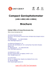
&
INSTALLATION INSTRUCTIONS
USER GUIDE
USB POWER SENSOR PWR-6G+
®
ISO 9001 ISO 14001 AS 9100 CERTIFIED
P.O. Box 350166, Brooklyn, New York 11235-0003 (718) 934-4500 Fax (718) 332-4661
SensorGuide.indd 1
10/8/08 11:37:53 AM
INSTALLATION INSTRUCTIONS
& USER GUIDE
Mini-Circuits...the solid source for
Signal Processing Solutions For:
COMMUNICATIONS • WIRELESS & CELLULAR PRODUCTS
MEDICAL • TEST INSTRUMENTATION • SATELLITE LINKS • RECEIVERS
PC ASSEMBLIES • COMPUTER • DIGITAL & ANALOG DATA ACQUISITION
UHF/ VHF TRANSMITTERS • TELEPHONY • CABLE / TV BROADCASTING
MILITARY • AIRCRAFT & AEROSPACE • RADAR
2
®
P.O. Box 350166, Brooklyn, New York 11235-0003 (718) 934-4500 Fax (718) 332-4661
ISO 9001 ISO 14001 AS 9100 CERTIFIED
SensorGuide.indd 2
10/8/08 11:37:54 AM
USB POWER SENSOR PWR-6G+
IF/RF Microwave components
Mini-Circuits Commitment to Quality & Customer Satisfaction
ISO 9001, ISO 14001 & AS 9100 Certification & Registration
ISO 9001 enhances our devotion to quality. Through a process of planning
and prevention, it helps assure customer satisfaction today and in the future.
ISO 14001 is the centrepiece of Mini-Circuits commitment to compliance with
environmental regulations. It assures conformance with our stated environmental
policies, and demonstrates our passion to implement, maintain, and continually
improve our environmental management system.
AS 9100 provides the framework to help ensure that all aspects of the design,
manufacture and support of our aerospace products meet their design
specifications and intended functions.
3
IF/RF MICROWAVE COMPONENTS For detailed performance specs & shopping online see
SensorGuide.indd 3
10/8/08 11:37:55 AM
INSTALLATION INSTRUCTIONS
Contents
& USER GUIDE
Page
Introduction. . . . . . . . . . . . . . . . . . . . . . . . . . . . . . . . . . . . 5.
Performance . . . . . . . . . . . . . . . . . . . . . . . . . . . . . . . . . . . 6
Installation Instructions Getting Started
and Software Setup . . . . . . . . . . . . . . . . . . . . . . . . . . 7-10
Measurement Instructions. . . . . . . . . . . . . . . . . . . . . . 11-13
Software Features
. . . . . . . . . . . . . . . . . . . . . . . . . . 14-16
Software License agreement. . . . . . . . . . . . . . . . . . . . 17-19
Support Centers . . . . . . . . . . . . . . . . . . . . . . . . Back Cover
4
®
P.O. Box 350166, Brooklyn, New York 11235-0003 (718) 934-4500 Fax (718) 332-4661
ISO 9001 ISO 14001 AS 9100 CERTIFIED
SensorGuide.indd 4
10/8/08 11:37:56 AM
USB POWER SENSOR PWR-6G+
Introduction
Traditionally, when you want to measure power of a signal source like an
oscillator, frequency generator, mixer output or an amplifier you normally think
of a bulky and expensive bench top power meter for the task. Not any more.
Mini-Circuits’ has developed a Universal Serial Bus (USB) enabled Power
Sensor PWR-SEN-6G+ that breaks away from that norm. In conjunction with
a power data analysis software, the PWR-SEN-6G+ Figure 1 turns your
laptop or desktop PC into an RF/Microwave Power Meter for measuring
power of continuous wave (CW ) signals from 1 MHz to 6 GHz.
Figure1 Mini-Circuits’ USB Power Sensor
PWR-SEN-6G+ with a 50 Ohm Type N (male),
and a Type N (female) to SMA (male) adaptor
Capable of measuring
average power of CW signal
levels from -30 dBm to +20 dBm for signals
in the 1 MHz to 6 GHz frequency range, the
PWR-SEN-6G+ offers a low cost replacement solution for
conventional RF/Microwave power meters with the benefits of data storage,
portability, post processing and Internet connectivity. In addition, unlike
conventional bench top instruments, no external power supply is needed
and it does not require any reference signal calibration. As a result,
it offers lighter weight, and makes field operation and installation easy and
simple. For attachment to a device under test (DUT), it offers a 50 Ohm
Type N (male) connector. Additionally, for connection flexibility, it also comes
with a Type N (female) to SMA male adaptor Figure 1, while the USB
interface cable connects the power sensor to a notebook or a PC with USB
ports. In essence, it provides an easy plug-and-play USB connectivity to a
PC, thereby, eliminating the need for a separate conventional power meter.
5
IF/RF MICROWAVE COMPONENTS For detailed performance specs & shopping online see
SensorGuide.indd 5
10/8/08 11:37:57 AM
INSTALLATION INSTRUCTIONS
& USER GUIDE
Performance
Features
• Operating frequency range of 1 MHz to 6 GHz
• 50 dB dynamic range, -30 dBm to +20 dBm
• Good VSWR, 1.1:1 (typical)
• Accuracy: ±0.15 dBm (typical)
• Linearity at 25 C is ±0.1 dBm (typical)
• Measurement speed is 200 ms
• No calibration after powering on (plug-in and measure)
• No external power supply is needed
• 16 simultaneous testing channels
• Temperature compensated
• Fully loaded power data analysis software
• Averaging of measurements
• Scheduled data recording
• Multi-Sensor support
• Interface with test software
Key system requirements for the sensor are shown in Table 1.
While absolute maximum power ratings are given in Table 2.
Table1 System requirements
System
Requirements
Interface
USB 1.1/USB 2.0
Host Operating System
Windows 98, Windows XP, Windows Vista , Windows 2000
Hardware
Pentium III or higher, RAM 512 Mb, USB port
Table 2 Absolute maximum ratings
Parameter
Ratings
Operating temperature
0°C to 50°C
Storage temperature
-30°C to 70°C
Current (via host USB)
40 mA (+5 V )
DC voltage at RF port
15 V
CW power
+27 dBm
6
®
P.O. Box 350166, Brooklyn, New York 11235-0003 (718) 934-4500 Fax (718) 332-4661
ISO 9001 ISO 14001 AS 9100 CERTIFIED
SensorGuide.indd 6
10/8/08 11:37:57 AM
USB POWER SENSOR PWR-6G+
Software Features
User friendly, easy to install software, enables
the user to record data and present it by:
• Power Output vs. Time graph
• Text file
• Excel spreadsheet file
Measurements can be performed according to a time
schedule defined by the user.
Furthermore, the software offers an option to define minimum and maximum limits of measurements, defining ranges of interest, so that any deviation from
defined limits is recorded and marked with a tracer:
Power Output vs. Time graph will have red lines on the Power axis at defined limits.
Excel and Text files: any result which exceeds limit will be marked by an asterisk *.
For full details on software options, see page 11
Getting Started and Software Setup
Insert the Mini-Circuits USB power sensor installation CD into the CDROM
device. If installation does not start automatically, run install.exe from <CD
drive> root directory. The Installation Window will appear, Figure 2.
Figure 2 Installation window
Click on the “Install Now” box. Accept the license agreement
and click continue, see Figure 3.
Figure 3 Licence agreement
7
IF/RF MICROWAVE COMPONENTS For detailed performance specs & shopping online see
SensorGuide.indd 7
10/8/08 11:37:58 AM
INSTALLATION INSTRUCTIONS
& USER GUIDE
Getting Started And Software Setup continued
The installation program will launch, to install Click on”OK” in the
“Mini-Circuits USB Power Meter Setup” message box, see Figure 4.
Figure 4 Mini-Circuits USB Power Meter setup window
The default directory for the program setup is “C:\ Program Files\ USB
Power Meter \”. Click on ‘Change Directory’ if you want to install under
a different directory. Click the setup button to begin the installation of the
USB Power Sensor. See Figure 5.
Figure 5 Setup window
The Program Group
message box will
appear and you may
change the Program
Group name or leave
it as “Mini-Circuits
USB Power Meter”.
Click on “Continue”
to proceed,
see Figure 6.
8
Figure 6 Program group window
®
P.O. Box 350166, Brooklyn, New York 11235-0003 (718) 934-4500 Fax (718) 332-4661
ISO 9001 ISO 14001 AS 9100 CERTIFIED
SensorGuide.indd 8
10/8/08 11:37:58 AM
USB POWER SENSOR PWR-6G+
You have completed the Mini-Circuits USB Power Meter setup successfully,
Click ”OK”, see Figure 7.
Figure 7 Mini-Circuits USB Power Meter setup Complete
Installation of USB Power Sensor Hardware
With the Mini-Circuits USB power sensor installation CD into the CDROM
device. Connect the power sensor to the PC USB port.
The New Hardware Wizard window will appear, Select “No, not this time“
and Click Next to continue, see Figure 8.
Figure 8 Found new hardware window
The “Welcome to
the Found New
Hardware Wizard”
window will appear,
Select “Install from
a list or a specific
location (Advanced)”
and Click Next to
continue,
see Figure 9.
Figure 9 Found new hardware wizard window
9
IF/RF MICROWAVE COMPONENTS For detailed performance specs & shopping online see
SensorGuide.indd 9
10/8/08 11:37:58 AM
INSTALLATION INSTRUCTIONS
& USER GUIDE
Installation Of USB Power Sensor Hardware continued
The Found New Hardware Installation Options window will appear: see Figure 10.
Select the first option: “Search for the best driver in these locations.”
Click and CLEAR the check mark in the “Search removable media
(floppy, CD-ROM…)” box.
Click and Check ”Include this location in the search:” box.
Click on Browse to choose location of the drivers for the Mini-Circuits USB
Power Sensor on the installation CD, <drive>:\drivers (where <drive> is your
CD-ROM drive letter, for example; ‘D:/drivers’). Click Next to continue.
Figure 10 Found new hardware wizard installation options window
A Hardware Installation warning window will appear,
Click on “Continue Anyway”, see Figure 11.
Figure 11 Hardware installation warning window
The installation of the USB Power Senor drivers is complete,
Click on “Finish” to close the wizard.
10
®
P.O. Box 350166, Brooklyn, New York 11235-0003 (718) 934-4500 Fax (718) 332-4661
ISO 9001 ISO 14001 AS 9100 CERTIFIED
SensorGuide.indd 10
10/8/08 11:37:58 AM
USB POWER SENSOR PWR-6G+
Measurement Instructions
After installation of the software and driver for activating the Power Sensor,
measurements can be run.
Connecting The Power Sensor
Plug in the push-pull connector to the end of the USB Power Sensor.
Plug in the USB connector to the USB port on the computer.
Run the Mini-Circuits USB Power Meter software.
In few seconds the main screen will appear, see Figure 13, and the
Power Meter is immediately available for measurements.
For achieving maximum accuracy, input your desired Frequency in the Freq
(1-6000MHz) box. Upon entering the Frequency in this window the results,
with respect to this Frequency, is instantly shown and without the need to
click any button to restart testing or refresh the screen.
Figure 13 Power meter software main screen
Recording Data
For recording data, click on the “Record” box and another window will open,
“Power Meter - Recording”, see Figure 14. There are two recording options;
1) Start Recording Now
Test data will start recording immediately. The Record box on the
main screen will change to “Recording” and turn red. To stop recording,
click on “Stop Record Now”.
2) Start Recording According To Schedule
Test data is recorded according to the time period defined at the
“Start Record At” settings.
The “Record Interval” setting changes the time period between recording
data points and can be set from a minimum of 1 second to a maximum
of 999,999 hours.
When the start date is set for a future time, the “Record” box on the
main screen Changes to “Record (Stand by record)” and its color changes
to yellow until the recording begins. At that time the box will change to
“Recording” and its color will change to red.
11
IF/RF MICROWAVE COMPONENTS For detailed performance specs & shopping online see
SensorGuide.indd 11
10/8/08 11:37:59 AM
INSTALLATION INSTRUCTIONS
& USER GUIDE
Measurements Instructions continued
Figure 14 Power meter recording window
Specification Limit Settings
Upper and lower test power results limits may be defined in the “Test Spec
Dn” (lower limit) and Test Spec Up (upper limit). Data point deviations from
these limits are indicated on the recorded test results report.
Power Measurement Results Format
The results may be displayed in dBm, milliwatts (mW), or microwatts (uW).
Data Output
Upon completion of recording, data results may be displayed by clicking:
View Graph, Open Data File, or Create Excel File. See Figure 14.
Figure 15 Power meter data group window
Power vs. Time Graph
Upon clicking “View Graph”, a graph appears, see Figure 15, that shows
power changes vs. time. Since the Power Meter contains a temperature
sensor, it is also possible to show the temperature in the Power Sensor body
vs time on the graph. This is to allow the user to correlate between Power
measurements and temperature. To display the temperature on the graph,
check mark “√” the “Show Temperature Graph” box.
12
®
P.O. Box 350166, Brooklyn, New York 11235-0003 (718) 934-4500 Fax (718) 332-4661
ISO 9001 ISO 14001 AS 9100 CERTIFIED
SensorGuide.indd 12
10/8/08 11:37:59 AM
USB POWER SENSOR PWR-6G+
Text Data File
Upon clicking “Open Data File”, a text file window will appear with the recorded
data, see Figure 16. The data record options defined by the user will be
shown on this text file, for example Date, Time, Frequency, upper and lower
Power limits, Temperature. Data results which are outside of the upper and
lower Power limits defined will be marked with an asterisk “*”.
Figure 16 Power meter text data window
Excel Spread Sheet File
Upon clicking the “Create Excel File”, an Excel spread sheet will appear,
see Figure 17. The data on the Excel sheet is displayed in a similar format
to the Text File (Open Data file). Note that the computer used must
have the Excel software installed.
Figure 17 Power meter excel data window
13
IF/RF MICROWAVE COMPONENTS For detailed performance specs & shopping online see
SensorGuide.indd 13
10/8/08 11:37:59 AM
INSTALLATION INSTRUCTIONS
& USER GUIDE
Additional Software Features
Data Averaging
In cases when the measured signal is not stable, it is possible to display the
test result based on the average of a number of measurements. The number
of measurements that the averaging is based on is defined by the user.
A check mark “√” is put in the “Averaging” box, see Figure 18, and number
of readings is typed into the “Avg. Count” window. The result is displayed
after the first average is calculated and the following calculated averages
are presented as testing progresses.
Figure 18 Data averaging
Relative
This feature allows the user to make a measurement relative to a previous data
reading. A check mark “√” is put in the “Relative” box, see Figure 19. This
enables saving a reading and then the main screen result of each additional
reading will be relative to the saved reading. The result will be presented in dB.
Offset Value
This feature allows the user to compensate for Loss or Gain in the Setup,
positive value compensates for a Loss, and negative value, for a Gain. A check
mark “√” is put in the “Offset Val.” box, see Figure 19, and Attenuation offset
value is typed into the “Offset Val.” window.
Reset Connection
If the Power Sensor is unplugged from the USB port, to continue taking
readings, the Power Sensor should be plugged back into the USB port and
click the “Reset Connection” box, see Figure 19.
Figure 19 Relative reading results
14
®
P.O. Box 350166, Brooklyn, New York 11235-0003 (718) 934-4500 Fax (718) 332-4661
ISO 9001 ISO 14001 AS 9100 CERTIFIED
SensorGuide.indd 14
10/8/08 11:37:59 AM
USB POWER SENSOR PWR-6G+
Add Sensor
This feature allows the user to work with more than one Power Sensor using the
same computer. While testing with one Power Sensor another Power Sensor
may be added by plugging the additional Power Sensor into a USB port and
click the “Add Sensor” box. A list of Power Sensors connected to the
computer will appear (listed under the Power Sensor serial number),
see Figure 20, the user should choose the appropriate Power Sensor.
Figure 20 List of multiple power sensors connected to computer
Working With Multiple Power Sensors
In case the user works with more than one Power Sensor, the software identifies
all the Power Sensors connected to the computer by the Power Sensor serial
number and presents a list of Power Sensor, see Figure 20.
Selecting Power Sensors
The user will select the desired Power Sensors according to the serial number.
To use all Power Sensors connected, click “Select All”.
To use each of the Power Sensors at a different test frequency, the
user must input the desired frequency for each Power Sensor
on the Main Screen (corresponding to each Power Sensor).
For ease of use, place a check mark “√” in the “Compact View”
box, see Figure 20.
Software Interfacing
Interfacing with test software for Power Sensor remote control can be done
easily through various set application and software tools including C++, Visual
Basic, Delphi and LabView. On the software disc supplied open the folder,
DLL_ActiveX and locate the file, mcl_pm_dll_ReadMe.txt. This has programming
instructions and an example included.
The library file, mcl_pm.dll is located in the same directory.
15
IF/RF MICROWAVE COMPONENTS For detailed performance specs & shopping online see
SensorGuide.indd 15
10/8/08 11:37:59 AM
INSTALLATION INSTRUCTIONS
& USER GUIDE
Additional Power Meter Software Features continued
Compact View
The Compact View allows the user to view the serial number of each
Power Sensor, Frequency, and Power reading, see Figure 21.
To change the Frequency of one of the Power Sensors, click on the screen and a
full screen view will be shown, where the relevant Frequency may be changed.
Figure 21 Compact view windows
Multiple Power Sensors
Multiple Power Sensors may be connected to a computer by using USB Hub.
(Recommend a maximum of a 4-port Hub per computer USB port,)
see Photo 1. To use 16 Power Sensors with one computer, four 4-port Hubs
should be used, for reference see Figure 22.
Photo 1 Example
of 4-port USB hub
Figure 22 Connection diagram for 16 power sensors
16
®
P.O. Box 350166, Brooklyn, New York 11235-0003 (718) 934-4500 Fax (718) 332-4661
ISO 9001 ISO 14001 AS 9100 CERTIFIED
SensorGuide.indd 16
10/8/08 11:38:00 AM
USB POWER SENSOR PWR-6G+
Software Licence Agreement
Your installation and use of this Power Meter software and any content contained herein (the “Software”)
is governed by the following terms of use (“Terms of Use”). Your installation and use of the Software is
expressly conditioned upon your acceptance of and compliance with the Terms of Use. You are required
to scroll through the Terms of Use below before clicking the “I Agree” button below.
ATTENTION: PLEASE READ THESE TERMS OF USE CAREFULLY BEFORE INSTALLING OR USING THIS
SOFTWARE. INSTALLING OR USING THIS SOFTWARE INDICATES THAT YOU ACCEPT THESE TERMS OF USE.
IF YOU DO NOT ACCEPT THESE TERMS OF USE, YOU MAY NOT INSTALL OR USE THIS SOFTWARE.
Acceptance. The following Terms of Use apply to all users of the Software and constitute a legal
agreement between you and your company (collectively, “Purchaser”), on the one hand, and Mini-Circuits,
on the other hand. By using the Software, Purchaser represent and warrant that: (i) it has or that an
appropriate representative of Purchaser has read, understands and agrees to be bound by the Terms of
Use and such representative has the power, authority and legal right to use the Software in accordance with
these Terms of Use on behalf of Purchaser; (ii) the use of this Software by such representative on behalf of
Purchaser has been duly authorized by all requisite action, corporate or otherwise; and (iii) these Terms of
Use are a valid, legal and binding obligation of Purchaser and its representatives, enforceable in accordance
with its terms. If Purchaser or its representative does not agree to these Terms of Use, neither Purchaser
nor its representative can use the Software. Mini-Circuits may amend these Terms of Use from time to time,
without notice, which amendments will be posted on Mini-Circuits’ website at www.minicircuits.com (the
“Website”) and will become effective upon posting. Purchaser’s continued use of the Software after posting
shall constitute Purchaser’s acceptance of and agreement to be bound by the amended Terms of Use. The
Terms of Use supplements and is in addition to: (x) any applicable written agreement(s) between
Mini-Circuits and Purchaser; and (y) any of Mini-Circuits’ then applicable policies; and (z) Mini-Circuits’
standard terms and conditions, which are applicable and which are located at https://www.minicircuits.com/
MCLStore. jsp (the items referenced in (x), (y) and (z) are collectively referred to as the “MC Terms”). In the
event there is any conflict between these Terms of Use and the terms contained within any other applicable
document, the terms which are more favorable to Mini-Circuits, as determined by Mini-Circuits, shall apply.
Reference to the terms “you”, “your” or “yourself” in these Terms of Use refers to both you and your company,
collectively, unless otherwise expressly indicated.
Warranty. Subject to the provisions set forth below, Mini-Circuits warrants only to the first purchaser
(“Purchaser”) of the USB Power Sensor (the “Part”) that on the date of shipment, the Part will conform to
Mini-Circuits’ applicable specification sheet in effect on the date of shipment, as may be further amended
by Mini-Circuits from time to time, provided that the Part is used with compatible components in appropriate
environments, within the applications and ranges for which they were manufactured, and in accordance
with instructions, assumptions and conditions stated in Mini-Circuits’ applicable specifications and technical
data, and provided further that they have not been used outside of absolute maximum ratings stated in
the applicable specification sheet or adversely affected by another component or element within or outside
of a given system or subject to improper installation, improper maintenance, abuse, accident, negligence,
alteration, misuse or the like. Conformance with the applicable specifications will be based on Mini-Circuits’
then applicable established performance criteria and measurement instructions. The warranty period for the
Part (excluding the Software) is twelve (12) months after shipment. The sole and exclusive remedy available
under this limited warranty is the repair or replacement of the Part furnished by Mini-Circuits which
Mini-Circuits determines to be defective or, if Mini-Circuits determines that this exclusive remedy fails its
essential purpose, the purchaser will, at its option, be entitled to a refund of the purchase price for the
products in question or a credit therefor.
LIMITATION OF WARRANTY. THERE ARE NO OTHER WARRANTIES HEREUNDER, WHETHER
EXPRESSED OR IMPLIED, ARISING BY OPERATION OF LAW OR OTHERWISE, INCLUDING,
WITHOUT LIMITATION, THE WARRANTIES OF MERCHANTABILITY, FITNESS FOR A PARTICULAR
PURPOSE AND ANY WARRANTIES CONCERNING INFRINGEMENT OR THE LIKE OR OTHERWISE
ARISING UNDER COURSE OF PERFORMANCE, COURSE OF DEALING OR USAGE OF TRADE.
UNLESS A STATEMENT IS SPECIFICALLY IDENTIFIED IN THIS BROCHURE AS A WARRANTY, THE
STATEMENTS MADE HEREIN RELATING TO THE Part ARE NOT EXPRESS WARRANTIES BUT ARE
MERELY MINI-CIRCUITS’ OPINION OR COMMENDATION OF THE Part. ANY DESCRIPTION OF THE
Part SPECIFIED HEREIN IS NOT INTENDED TO BE A WARRANTY, BUT IS FOR THE SOLE PURPOSE
17
IF/RF MICROWAVE COMPONENTS For detailed performance specs & shopping online see
SensorGuide.indd 17
10/8/08 11:38:00 AM
INSTALLATION INSTRUCTIONS
& USER GUIDE
Software Licence Agreement continued
OF IDENTIFYING THE Part AND IT DOES NOT CONSTITUTE A WARRANTY THE Part WILL CONFORM
TO THAT DESCRIPTION. SIMILARLY, THE USE OF ANY SAMPLES, GRAPHS, DATA CURVES,
MODELS, OR DRAWINGS IS ONLY FOR ILLUSTRATIVE PURPOSES AND DOES NOT CONSTITUTE
A WARRANTY THE Part WILL CONFORM WITH SUCH SAMPLES, GRAPHS, DATA CURVES,
MODELS, OR DRAWINGS. WAIVER OF CONSEQUENTIAL DAMAGES. UNDER NO CIRCUMSTANCES
WILL MINI-CIRCUITS BE LIABLE FOR ANY CONSEQUENTIAL, EXEMPLARY, INCIDENTAL, INDIRECT, OR
SPECIAL DAMAGES, OR LOST PROFITS, EXPENSES OR LOSSES DIRECTLY OR INDIRECTLY ARISING
OUT OF OR RELATING TO THE SALE OR USE OF THE Part OR USE OF THE Software FURNISHED BY
MINI-CIRCUITS REGARDLESS OF WHETHER THE LIABILITY RESULTED FROM ANY GENERAL OR
PARTICULAR REQUIREMENT OR NEED WHICH MINI-CIRCUITS KNEW OR SHOULD HAVE KNOWN OF.
For a full statement of the limited warranty offered by Mini-Circuits and the exclusive rights and remedies
thereunder, together with Mini-Circuit’s limitations of warranties and limitation of liability, please refer to
Mini-Circuit’s standard purchase order acknowledgment form. If you do not have this form, please contact
a Mini-Circuits representative and one will be provided promptly. Alternatively, visit Mini-Circuits’ website.
To access go to www.minicircuits.com/MCLStore/terms.jsp.
License of Use – Software. In conjunction with Purchaser’s purchase of the Part, Mini-Circuits grants
Purchaser a limited, revocable, non-exclusive, non-transferable license to use the Power Meter software
provided with the Part (the “Software”) only in connection with using the Part in accordance with the
provisions hereof (the “Purpose”) and for no other purpose whatsoever. Accordingly, Purchaser may not: (a)
modify, distribute, publish or transmit the Software for any public or commercial purpose; (b) copy, replicate,
or reproduce the Software in any form, or by any means, without prior written permission from Mini-Circuits;
(c) reverse-engineer, decompile or disassemble the Software; or (d) use the software other than for the
Purpose. Purchaser hereby acknowledges and agrees that the Software, related documentation, source
code, object code, fonts, and any related intellectual property (collectively, the “Software IP”) are the sole
and exclusive property of Mini-Circuits and that Purchaser has no right, title, or interest in any of the
Software IP. Purchaser owns only the media on which the Software IP is recorded, but Mini-Circuits retains
sole and exclusive ownership of the Software IP itself. Accordingly, this is merely a license to use the
Software subject to the provisions hereof and not a transfer of any other interest nor is it a transfer of title.
THE SOFTWARE IS PROVIDED “AS IS,” “WITH ALL FAULTS,” AND WITHOUT ANY EXPRESS OR IMPLIED
WARRANTY OF ANY KIND, ALL OF WHICH ARE HEREBY WAIVED.
Warning: The Software is provided to Purchaser with the Express understanding that any technical results
or data generated by the Part and/or Software does not constitute any technical or professional advice or
opinions rendered by Mini-Circuits, and, accordingly, Mini-Circuits assumes no liability in connection with
the use of such technical results or data.
Warning: Mini-Circuits is not responsible for the completeness, accuracy, and reliability of the Software or
the technical results or data derived from the Part or the Software, or the use of such Software or the
technical results or data derived therefrom. Purchaser’s installation of the Software is done so at Purchaser’s
sole discretion and risk and Purchaser is solely responsible for any loss of data or damage to any computer
that may result from the installation of such software by Purchaser. Mini-Circuits does not guarantee or
warrant that the Software is compatible with, or will perform in accordance with, Purchaser’s computers,
products, or systems, and Mini-Circuits hereby waives any and all liability in connection therewith. In
addition, Mini-Circuits does not guarantee or warrant that the Software is free of viruses, time bombs,
Trojan horses, worms, and other damaging computer programming routines or harmful components.
Miscellaneous
(a) The parties acknowledge and agree that this Terms of Use shall be a contract made in the United States,
State of New York. All questions pertaining to the validity, construction, execution and performance of this
Terms of Use shall be construed and governed in accordance with the domestic laws of the State of New
York (including, without limitation, the UCC), without giving effect to principles of (i) comity of nations or (ii)
conflicts of law, and this Terms of Use shall not be governed by the provisions of the U.N. Convention on
Contracts for the International Sale of Goods.
(b)(i) Any controversy or claim arising out of or relating to this Terms of Use, or the breach hereof, shall be
settled by arbitration in accordance with the United States Arbitration Act and administered by the
American Arbitration Association in accordance with its commercial arbitration rules, and judgment on
the award rendered by the arbitrators may be entered in any court having jurisdiction thereof.
18
®
P.O. Box 350166, Brooklyn, New York 11235-0003 (718) 934-4500 Fax (718) 332-4661
ISO 9001 ISO 14001 AS 9100 CERTIFIED
SensorGuide.indd 18
10/8/08 11:38:00 AM
USB POWER SENSOR PWR-6G+
The arbitration proceedings shall be conducted before a panel of three (3) neutral arbitrators. The place of
the arbitration shall be in New York, New York. Any award in an arbitration initiated under this Terms of Use
shall be in accordance with New York law, as more particularly specified in subparagraph (a) of this section.
The successful party will be entitled to be awarded all costs, including reasonable attorney’s fees, paid or
incurred by such prevailing party during the course of the arbitration proceedings.
In any arbitration initiated under this Terms of Use, the arbitrators will have no authority to award (i) injunctive
or other equitable relief, or (ii) consequential, exemplary, incidental, indirect or special damages, lost profits
or punitive or other damages not measured by the prevailing party’s actual direct damages, except as may
be required by statute and then only to the extent such requirement cannot, as a matter of law, be waived.
Any award shall include no injunction or direction to any party other than the direction to pay damages in
accordance with the provisions hereof.
(ii) Except as required by law, neither party nor any arbitrator may disclose the existence, content or results
of any arbitration hereunder without the prior written consent of Mini-Circuits and Purchaser.
(iii) If either party fails to proceed with arbitration as provided herein or unsuccessfully seeks to stay such
arbitration, or fails to comply with any arbitration award, or is unsuccessful in vacating or modifying the
award pursuant to a petition or application for judicial review, the other party shall be entitled to be awarded
costs, including reasonable attorneys’ fees, paid or incurred by such other party in successfully compelling
such arbitration or defending against the attempt to stay, vacate or modify such arbitration award and/or
successfully defending or enforcing the award.
By installation and use of this Software, Purchaser agrees to be bound by all applicable laws and
regulations that may pertain to the Software, and Purchaser agrees that the Software will not be used,
removed or exported from the United States or re-exported or released (i) to any of the following countries
or a national thereof: Cuba, Iran, North Korea, Sudan, Syria or any country specified in Country Group E
(as specified in the then current Supplement No. 1 to Part 740 of the U.S. Export Administration
Regulations) or (ii) to any Entity as specified in Entity List Supplement No. 4 to Part 744 of the U.S. Export
Administration Regulations or other country except in compliance with, and with all licenses, license
exceptions and approvals required under, the U.S. Export Administration Regulations and all other
applicable United States and foreign export laws, rules, restrictions and regulations, including those of
the U.S. Department of Commerce and other applicable United States agencies and authorities, as
amended from time to time. Diversion therefrom contrary to U.S. law is prohibited. If Purchaser chooses to
install or use this Software from outside the United States, Purchaser does so on its own initiative and is
responsible for compliance with applicable local laws.
Purchaser hereby reaffirms and agrees that the sales of parts by Mini-Circuits to Purchaser are governed
by the MC Terms, which are applicable. These Terms of Use and the MC Terms constitute and contain the
entire agreement between Mini-Circuits and Purchaser with respect to Purchaser’s purchase of the
Part and installation and use of this Software and supersedes and replaces all prior agreements, prepared
or otherwise, whether written or oral, concerning Purchaser’s purchase of the Part and installation and
use of this Software.
With regards to the Terms of Use, Mini-Circuits shall have the right, at its sole discretion, to modify, add
or remove any terms and conditions of the Terms of Use from time to time without notice or liability to
Purchaser. Any changes to the Terms of Use shall be effective immediately following the posting of such
changes on the Website. Purchaser agrees to review the Terms of Use from time to time and agree that
any subsequent use by Purchaser of this Software following changes to the Terms of Use shall constitute
Purchaser’s acceptance of such changes.
NOTE: THE TERMS REFERENCED ABOVE CONTAIN IMPORTANT INFORMATION ABOUT PURCHASER’S
RIGHTS AND OBLIGATIONS AS WELL AS LIMITATIONS AND EXCLUSIONS THAT MAY APPLY TO
PURCHASER. THEY CONTAIN LIMITATIONS OF LIABILITY AND WARRANTY INFORMATION. BY
CLICKING THE “I AGREE” BUTTON BELOW PURCHASER ACKNOWLEDGES THAT IT HAS READ,
UNDERSTANDS, AND AGREES TO BE BOUND BY THE TERMS OF USE. BY CLICKING THE “I DO NOT
AGREE” BUTTON BELOW PURCHASER ACKNOWLEDGES THAT IT DOES NOT AGREE TO THE TERMS
OF USE, AND PURCHASER WILL BE PREVENTED FROM DOWNLOADING, INSTALLING, OR USING ANY
INFORMATION, DATA, OR CONTENT FROM MINI-CIRCUITS UNDER THIS SOFTWARE.
19
IF/RF MICROWAVE COMPONENTS For detailed performance specs & shopping online see
SensorGuide.indd 19
10/8/08 11:38:00 AM
USB POWER SENSOR PWR-6G+
Need Help?
Contact our conveniently located support centers with any questions you
may have regarding the USB power sensor or any other inquiries.
Mini-Circuits SUPPORT CENTERS
America
North
Mini-Circuits
chiNA
Mitron, Inc.
Fuzhou, China
350003 P.R. China
86 591 87870001/2
[email protected]
718-934-4500
[email protected]
EUROPE
Mini-Circuits Europe
Surrey GU16 6LF England
44 1252 832600
[email protected]
Beijing, China
[email protected]
Shanghai, China
[email protected]
Shenzhen, China
[email protected]
Israel
Ravon Electronics Ltd.
Kiryat Bialik 27000 Israel
972 4 8749100
[email protected]
Chengdu, China
[email protected]
Xian, China
[email protected]
India
Urjita Electronics Pvt. Ltd.
Chennai 600045 India
91 44 2 2622575
[email protected]
You can always Visit Us at
Hong Kong
[email protected]
Singapore,
Malaysia, Thailand
Mini-Circuits Technologies
Penang 11900, Malaysia
604 646 2828
[email protected]
Taiwan, Philippines
Mini-Circuits Taiwan Ltd.
Taoyuan Hsien, Taiwan ROC
886 3 318 4450
[email protected]
®
ISO 9001 ISO 14001 AS 9100 CERTIFIED
P.O. Box 350166, Brooklyn, New York 11235-0003 (718) 934-4500 Fax (718) 332-4661
SensorGuide.indd 20
10/8/08 11:38:01 AM