1
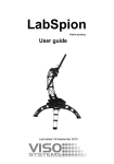
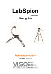
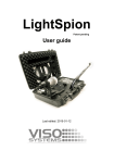
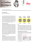
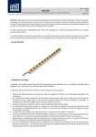
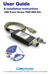
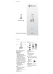
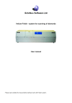
Compact Goniophotometer (LSG-1200/LSG-1200A) Brochure Global Office of Lisun Electronics Inc. http://www.Lisungroup.com Lisun Group (Hong Kong) Limited Add: Room C, 15/F Hua Chiao Commercial Center, 678 Nathan Road, Mongkok, Kowloon, Hong Kong Tel: 00852-68852050 Fax: 00852-30785638 Email: [email protected] Lisun Electronics (Shanghai) Co., Ltd Add: Room 405, North Building, No. 1021, CaoYang Road, Putuo District, Shanghai, 200062, China Tel: +86(21)5108 3341 Fax: +86(21)5108 3342 Email: [email protected] Lisun Electronics Inc. (USA) Add: 445 S. Figueroa Street, Los Angeless, CA 90071, U.S.A. Email: [email protected] Lisun China Factory Add: NO. 37, Xiangyuan Road, Hangzhou City, Zhejiang Province, China Tel: +86-189-1798-9698 Email: [email protected] Lead in CFL & LED Test Instruments Lisun Electronics Inc. [email protected] www.Lisungroup.com Compact Goniophotometer The compact goniophotometer of LSG-1200/LSG-1200A, various dark room are selectable according to the size of tested lamps. It is used to measure the luminous intensity distribution curve, intensity data, spread angle and other parameters for Chip LED, LED Module, LED Bulb, LED spotlight and CFL Lamp as below: -Page 1 - Lisun Electronics Inc. [email protected] www.Lisungroup.com Working Principle z Principle of detector Instead of selenium photocell, silicon photocell is widely used in photometry measurement because of its high stability and long service life. But the light sensitive response curve of silicon photocell has a big difference comparing with CIE1931 standard visual function V (λ). International practice is to amend the curve with special designed color filter, and the amendment result influence the test accuracy directly. With the high amendment capability, this detector reaches the requirement of National grade 1. Its construction illustrated as Picture 1: Light in direction Silicon photocell White piece (cosine revising) Color filter Picture1: Construction Illustration for Detector z Test principle of luminous intensity Picture 2: Test principle chart of luminous intensity D: tested part G: current source PD: contain the photodetector of spectral diaphragm D1 of which the area is A D2、D3: remove stray light d: distance between tested part and spectral diaphragm D1 Note 1: adjust the tested part to make its machine axis get through the aperture of detector center. Note 2: the spectral sensitivity of detector should be calibrated to CIE standard luminosity observer spectral curve within the spectral wavelength range transmitted by the tested part. User should select non spectral selectable detector to test -Page 2 - Lisun Electronics Inc. [email protected] www.Lisungroup.com radiation data. Test radiation parameters should be selective of non-spectrum light detector. Test system should be used by standard device revised base on the distance d and the diaphragm D1. According to the square law of illumination intensity and cosine, obtain the following formula: E = I cos θ/ r2 Through measurement the Brightness contrast that can calculate the average light intensity I = E*r2 ( due to the tested device peak same as test system, so r is aforementioned d). Based on the above light intensity measuring principle, using a known light intensity standard lamp calibration of this instrument after the measurement process in the system to get the measured values multiplied by the scaling factor is in the device under test under the conditions of illumination, and then were multiplied by the square of different distances d get intensity. z Spatial light intensity distribution of the test Stepper electric motor movement control by microprocessor to make sure angle precision strictly, measuring the various angles of the luminous intensity values. Microprocessor will send sampling value to PC software by RS-232C, it will display the distribution curve and important parameters after software calculate. z Spread angle and drift angle calculations From the measured spatial intensity distribution can get the opposite angle of half maximum light intensity point:θ1, θ2, half-intensity angle θ (50%) = | θ2-θ1 |, can also calculation θ(10%)、θ(25%) and θ(75%) as well as the same way. Drift angle is included angle between peak value light intensity and machinery value. z Calculated luminous flux from the light intensity distribution curve Calculated the general luminous flux from the light intensity distribution curve, in theory, should use the following formula φ = ∫ Id ω As can be seen, light intensity distribution curve can't express by mathematical functional actually, and therefore need to use some methods of solution of the integral equation. If the device under testing is set in the center of the sphere like Picture3. Solid angle facing the center of a sphere can be used between the latitude and the vertical angle θ and θ + δθ defined between the girdle to expression. So the emergent luminous flux from girdle θ1 to θ2 as follow: φ=∫ Id ω=∫2πIsinθdθ=2π(cosθ1-cosθ2) -Page 3 - Lisun Electronics Inc. [email protected] www.Lisungroup.com Formula I(cd) express average light intensity in girdle, 2π(cosθ1-cosθ2) is modulus of girdle (ZF) Picture 3. Calculated girdle coefficients This method same as test system which make use of multiply-accumulate between girdle coefficients and light intensity to solve for luminous flux, can take full advantage of the measured light intensity to distributed data. Perspective of the user selected sampling interval as δθ, the hemisphere divided into 90/δθ girdle, using the measured data of light intensity distribution to count average light intensity values of corresponding angle girdle, and then multiplied by the corresponding factor girdle is luminous flux of this girdle. Last accumulate all of flux girdle can get the equivalent luminous flux throughout the hemisphere. z Host Rear Panel Diagram Picture 4 1、 the measured lamp power supply interface; 2、 RS232 communication interface connected with computer; 3、 power fuse tube socket; 4、 power socket; 5、 switch. -Page 4 - Lisun Electronics Inc. [email protected] www.Lisungroup.com Technical Specification: LSG-1200/LSG-1200A has included a dark room Test range of luminosity: 0.1~30,000lx Test accuracy of luminosity: Class 1 Test range of angle: LSG-1200: Horizontal angle: -0°~360° (Manual) Vertical angle: -90°~+90°(Automatic) LSG-1200A: Horizontal angle: -0°~360° (Automatic) Vertical angle: -90°~+90°(Automatic) Test accuracy of angle: ±0.2° Angle interval: Horizontal angle: 1°/5°/10°/15°/22.5°/30°/45°/90° Vertical angle: 0.5°/2°/1.5° Measure the maximum size of lamps: 180mm The distance between the tested lamp and detector is 316mm/1000mm Measure beam angle automatically: staple half intensity angle as well as 1/4 intensity angle, 3/4 intensity angle and 1/10 intensity angle which meets the special requirements. Draw spatial luminous intensity distributional curve automatically (polar coordinates and right-angle coordinates) Measured data match with international standard form (IES) and can be applied for lighting design by other lighting design software such as Dialux RS-232C interface, compatible with all kinds of computers Meets the requirements of IEC•CIE standards Work power supply: a) Power supply voltage: AC 220V±10% b) Power frequency: 50Hz/60Hz c) Power dissipation: 35VA Requirement of working environment: a) Allowable working environmental temperature: 0℃~40℃ b) Best temperature for normal test: 25℃±5℃ c) Relative humidity: ≤65%R.H Typical oversea market customers: *********** Please get the reference customers’ information from Lisun Oversea Sales Dept. Software and Test Report Format is similar as LSG-1800 -Page 5 -