1
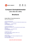
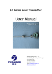
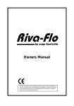
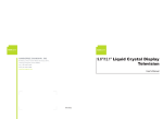
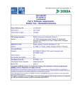
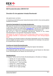
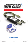
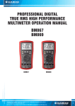
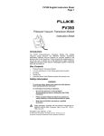
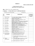
User’s Manual Digital CC and CV DC Power Supply (DC12010) Global Office of Lisun Electronics Inc. http://www.Lisungroup.com Lisun Group (Hong Kong) Limited Add: Room C, 15/F Hua Chiao Commercial Center, 678 Nathan Road, Mongkok, Kowloon, Hong Kong Tel: 00852-68852050 Fax: 00852-30785638 Email: [email protected] Lisun Electronics (Shanghai) Co., Ltd Add: 113-114, No. 1 Building, Nanxiang Zhidi Industry Park, No. 1101, Huyi Road, Jiading District, Shanghai, 201802, China Tel: +86(21)5108 3341 Fax: +86(21)5108 3342 Email: [email protected] Lisun Electronics Inc. (USA) Add: 445 S. Figueroa Street, Los Angeless, CA 90071, U.S.A. Email: [email protected] Lisun China Factory Add: NO. 37, Xiangyuan Road, Hangzhou City, Zhejiang Province, China Tel: +86-189-1799-6096 Email: [email protected] Lead in CFL & LED Test Instruments Lisun Electronics Inc. [email protected] www.Lisungroup.com CONTENT TABLE Chapter 1 Introduction ………………………..……………..………………… 2 Chapter 2 Basic Principle and Notes………………………..…………… 2 Chapter 3 Function and Major Technical Indexes………………… 3 Chapter 4 Operation Instruction………………………..………………… 4 Chapter 5 Packing List………………………..………………………………… 7 -Page 1 - Lisun Electronics Inc. [email protected] www.Lisungroup.com Chapter 1 Introduction Thank you for purchasing DC12010 Digital CC and CV DC Power Supply. Please make sure that all the accessories which are listed in chapter 5 well completed before you use the instrument. If there is something lost or mistaken. Please contact us as soon as possible to safeguard your rights and benefits. The user’s manual includes the basic principle, main function, major technical indexes and operation. In order to use it correctly and avoid any unnecessary damage, please read the manual carefully before operating the instrument. Please keep this manual for future reference. DC12010 is linear DC power supply of both constant current and constant voltage. It has various advantages, such as high stability, high accuracy, convenient operation and continuous adjustment of output current and voltage, etc. with digital high accurate current display dial, it is an ideal power supply, especially suitable for spot monitoring. DC12010 is easy to be adjusted with three adjusting gears .All the buttons can be locked if needed ,DC12010 can be recovered easily only with one button. With 16-bit high speed CPU and high accurate D/A, A/D, it can guarantee the high performance and high stability .Constant current state and constant voltage state can be shifted automatically. Chapter 2 Notes When connecting to loads ,please pay attention to the polarity of terminals to avoid damage to the instrument .The terminals in red is positive output end of power supply , while the terminals in black is negative output end of power supply. 1. If it is not a long- distance sampling. Please click the button "inside”, which can guarantee the test accuracy. 2. Press "reset" button before power off or load disconnection. 3. DC12010 should be connected to ground reliably. 4. Keep the interval between power on and power off more than 3 minutes. 5. Keep all parts of these power supply well ventilated to promote the quality. 6. Basic principle -Page 2 - Lisun Electronics Inc. [email protected] Network of Error Input end of power Correction Coefficient Adjusting AC/DC conversion www.Lisungroup.com tubes of large power Current sampling and filtering Output Display Electrical Button CPU parameter analysis Figure 1 Principle Figure of DC12010 Chapter 3 Function and Major Technical Indexes 3.1 Major Technical Indexes 1) Voltage stability : ≤ 5×10⁻⁵ reading value+ 2mV 2) 4 grades of Voltage range : 5V/10V/25V/50V 3) Current stability:≤ 1×10⁻⁴ reading value+0.5mA 4) 4 grades of Current range : 0.5A/1A/2.5A/5A 5)voltage resolution:0.0001V(0.0000V~3.000V);0.001V(3.000V~50.000V); 6)Voltage accuracy:± (0.02% reading +0.01% range +1digit); 7)current resolution:0.0001A(0.0000A~5.000A); 8)current accuracy:± (0.02% reading+0.01%range+1digit); 9)Max output power:750VA 10)Max output voltage:120V 11)Max output current:10A 12)voltage ripple in stability state (Vrms):10mV 13)current ripple in stability state (Irms) :10mA 3.2 Work Environment Environmental Temperature:23℃ 15℃ ; Relative humidity≤55%±20%, Power supply: AC 220±11V; Frequency: 50/60HZ 3.3 Outside dimension (W×H×D): 410mm×148mm×400mm 3.4 Weight: about 14 kg -Page 3 - Lisun Electronics Inc. [email protected] www.Lisungroup.com Chapter 4 Operation Instruction 4.1 Front Panel Instruction Figure2 front panel 1. "Sampling”: Press this button to convert the sampling methods between "inside" and "outside''.”Inside" means sampling from inside, while "outside'' means sampling from outside. 2. "Voltage V": display set voltage value when set-led is bright (V) or display test voltage value (V). 3. "CV": The indicator is on when it is in voltage stability state 4. "CC": The indicator is on when it is in current stability state. 5. "Current A": display set current value when set-led is bright (A)or display test current value(A). 6. "Alarm": After a long-time and durable output, The temperature will rise accordingly, If the temperature is too high, the instrument CC&CV will alarm with "buzz" and both output current and output voltage will drop into zero. Press "reset” button to restart test. 7. "Reset ": press this button to clear output current value and output voltage value. 8. "Setup": Press this button to the indicator, "Voltage V" and "Current A" display the set current value, Press this button to extinguish the indicator, "Voltage V" and "Current A" display the test current value. 9. "Slow": Press this button to determine whether the voltage will build up to the rated value or output voltage will cut off gradually when press the output button. Press the button, and then the corresponding indicator turns up and output voltage will be build up or cut off gradually. 10. “OVP” Set limits on voltage 11. “Output”: Output or close. 12. "key lock”: lock the current state, press it again to unlock the state. 13. "Power”: power on or power off. 14. "voltage adjust”: Clockwise rotation can increase the voltage value ,while -Page 4 - Lisun Electronics Inc. [email protected] www.Lisungroup.com counter-clockwise rotation can reduce the voltage value .If exceeding the limit , The instrument CC&CV will alarm with "buzz" 15. "current adjust": :Clockwise rotation can increase the current value ,while counter-clockwise rotation can reduce the current value .If exceeding the limit , The power source will alarm you with "buzz" 16. "Output+": Positive output terminal of power supply "Output-": Negative output terminal of power supply 4.2 Back Panel Instruction Figure3 Rear panel 1. Ventilation 2."Output+": positive output terminal of power supply (in red) 3. "S+" in red: Positive terminal of sampling in a long distance 4. "S-" in black: negative terminal of sampling in a long distance 5."Output+": negative output terminal of power supply (in black) 7. Communication port 8. Instrument code 9. “Fuse seat”: protective tube inside 10. "Power outlet": filter inside. Including filtering external connection and supply power. 4.3 Operation Instruction Please follow the operation step as follows to protect the instrument and load from destroying: 1. Please connect the power cord and make sure the instrument is well connected to ground. 2. Range of Rated Voltage for the instrument: 220±11V. 3. Please connect the load to the output terminals of power supply. (Positive output terminal of power supply is in red while negative output terminal of power supply is in black) -Page 5 - Lisun Electronics Inc. [email protected] www.Lisungroup.com 4. Preheating the instrument for 10 minutes 5. Adjustment A. If CC&CV is desired to be used as a power supply of stable voltage. Please operate as follows: First: Adjusting the current until the indicator of CV illuminated by current turn-knob, Secondly :Adjusting the voltage to attain the desired value by voltage turn-knob and then the voltmeter will display voltage value ,while ampere meter will display corresponding value according to the formula (IO= UO /RL). Thirdly: when the indicator of CV is off and the indicator of CC is on, it means entering current-limited state .At this time, you need to increase current by current turn-knob at this time. The instrument will enter the state of stable voltage again. B. If CC&CV is desired to be used as a power supply of stable current. Please operate as follows: First: Adjusting the voltage until the indicator of CC illuminated by voltage turn-knob. Secondly: Adjusting the current to attain the desired value by current turn-knob and then the ampere meter will display current value ,while voltmeter will display corresponding value according to the formula (IO= UO /RL). Thirdly: when the indicator of CC is off and the indicator of CV is on, it means entering voltage-limited state. At this time, you need to increase voltage by voltage turn-knob. The instrument will enter the state of stable current again. C. If the power supply will output large current, please choose "outside" by clicking "sampling" button on front panel what's more. Pay attention to the polarity of red and black terminals. Make sure that the positive end of load is connected to the "S+" terminals in red, while negative end of load is connected to the "S-" terminals in black. 6. Change loads Press "reset" button before load disconnection. Remove the former one and install new one. 6. Press "reset" button before power off. -Page 6 - Lisun Electronics Inc. [email protected] www.Lisungroup.com Chapter 5 Packing List 1 Main Instrument 1 2 Power Cord 1 3 Communication Line 1 4 User's Manual 1 5 Calibrate Certificate 1 6 Guarantee Card 1 -Page 7 -