1
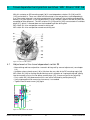
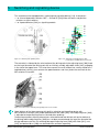
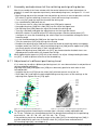
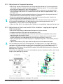
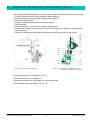
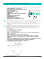
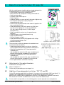
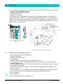
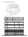
5.1 Assembly and adjustment of the switching and signalling device After the assembly of the linear actuator with the control element has been effected acc. to chapter 2.3, mount the separate or previously removed adjusting lever (see figure 5.1.1-1 and 5.1.1-2): Move driving rod out of the actuator into end position by means of manual operation, until the DE-switch S1 will be switching (if necessary, check with measuring instrument) Turn a nut [287] onto the lug of the thread of the driving rod Lay a toothed disc [290] onto the nut Turn the cam shaft in a way that the tappet lever [259] points upward Hang adjusting lever [260] with slider [261] into the slot of the tappet lever Set adjusting lever [260] above the lug of the thread of the driving rod Turn cam shaft back and guide the adjusting lever via the lug of the thread With WE-switches S3 and S6 built on DE-mounting angles slide the contact piece [37] (see figure 4.1) over the threaded lug; the switch finger must herewith be rectangular to the mounting angle Lay the second toothed disc [290] over the lug of the thread Turn the second nut [287] onto the lug of the thread Readjust the adjusting lever [260] on the lug of the thread of the driving rod by turning both hexagon socket nuts [287] in a way that the adjusting lever [260] and the tappet lever [259] are exactly parallel to each other in their inclined position Tighten the adjusting lever [260] with nuts [287]; pay hereto attention that both levers are aligned parallel to each other also viewed from the top When tightening the upper nut [287] with a fork wrench size of jaw 10 keep holding the lower nut [287], in order to prevent a torsion of the threaded lug. 5.1.1 Adjustment of a different positioning travel If it is necessary to adjust a different positioning travel, this must be carried out in end position of “driving rod being moved out”. Adjusting lever [260] and tappet lever [259] must be exactly parallel to each other in their inclined position. Untighen the flat nut [278] from the slider [261] with fork wrench size of jaw 10 Shift slider [261] and adjust the desired positioning travel by means of the markings on the adjusting lever; tighten flat nut [278] again 266 288 282 273 S4 S5 281 278 272 252 260 261 287 290 283 291 253 275 Figure 5.1.1-1: Switching and signalling device Figure 5.1.1-2: Position of the switching and signalli ng device The positioning travel concerning this actuator type is infinitely variably adjustable from 16–75 mm. Therefore any intermediate position can be adjusted (markings for the positioning travel with 16 – 20 – 25 – 30 – 35 – 40 – 50 – 60 – 70 – 75 mm). If the positioning travel was altered by means of the slider [261] in the adjusting lever [260], it must be readjusted in each case, if the WE-switch S3 [124] has been mounted on the DE-mounting angle [36] (see chapter 4.1). Operating instructions linear actuator “SBA 12 – SBA 20 – SBA 45” Electric Valve Actuator type MT90 Marine 21 22 ofA/S 29 Clorius page Controls