1
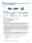
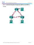
Lab - Troubleshooting DHCPv4 Topology © 2013 Cisco and/or its affiliates. All rights reserved. This document is Cisco Public. Page 1 of 8 Lab - Troubleshooting DHCPv4 Addressing Table Device R1 Interface IP Address Subnet Mask Default Gateway G0/0 192.168.0.1 255.255.255.128 N/A G0/1 192.168.1.1 255.255.255.0 N/A S0/0/0 (DCE) 192.168.0.253 255.255.255.252 N/A S0/0/0 192.168.0.254 255.255.255.252 N/A S0/0/1 (DCE) 209.165.200.226 255.255.255.252 N/A ISP S0/0/1 209.165.200.225 255.255.255.252 N/A S1 VLAN 1 192.168.1.2 255.255.255.0 192.168.1.1 S2 VLAN 1 192.168.0.2 255.255.255.128 192.168.0.1 PC-A NIC DHCP DHCP DHCP PC-B NIC DHCP DHCP DHCP R2 Objectives Part 1: Build the Network and Configure Basic Device Settings Part 2: Troubleshoot DHCPv4 Issues Background / Scenario The Dynamic Host Configuration Protocol (DHCP) is a network protocol that lets the network administrators manage and automate the assignment of IP addresses. Without DHCP, the administrator must manually assign and configure IP addresses, preferred DNS servers, and the default gateway. As the network grows in size, this becomes an administrative problem when devices are moved from one internal network to another. In this scenario, the company has grown in size, and the network administrators can no longer assign IP addresses to devices manually. The R2 router has been configured as a DHCP server to assign IP addresses to the host devices on router R1 LANs. Several errors in the configuration have resulted in connectivity issues. You are asked to troubleshoot and correct the configuration errors and document your work. Ensure that the network supports the following: 1) The router R2 should function as the DHCP server for the 192.168.0.0/25 and 192.168.1.0/24 networks connected to R1. 2) All PCs connected to S1 and S2 should receive an IP address in the correct network via DHCP. Note: The routers used with CCNA hands-on labs are Cisco 1941 Integrated Services Routers (ISRs) with Cisco IOS Release 15.2(4)M3 (universalk9 image). The switches used are Cisco Catalyst 2960s with Cisco IOS Release 15.0(2) (lanbasek9 image). Other routers, switches and Cisco IOS versions can be used. Depending on the model and Cisco IOS version, the commands available and output produced might vary from what is shown in the labs. Refer to the Router Interface Summary Table at the end of this lab for the correct interface identifiers. Note: Make sure that the routers and switches have been erased and have no startup configurations. If you are unsure, contact your instructor. Required Resources 3 Routers (Cisco 1941 with Cisco IOS Release 15.2(4)M3 universal image or comparable) © 2013 Cisco and/or its affiliates. All rights reserved. This document is Cisco Public. Page 2 of 8 Lab - Troubleshooting DHCPv4 2 Switches (Cisco 2960 with Cisco IOS Release 15.0(2) lanbasek9 image or comparable) 2 PCs (Windows 7, Vista, or XP with terminal emulation program, such as Tera Term) Console cables to configure the Cisco IOS devices via the console ports Ethernet and serial cables as shown in the topology Part 2: Build the Network and Configure Basic Device Settings In Part 1, you will set up the network topology and configure the routers and switches with basic settings, such as passwords and IP addresses. You will also configure the IP settings for the PCs in the topology. Step 1: Cable the network as shown in the topology. Step 2: Initialize and reload the routers and switches. Step 3: Configure basic settings for each router. a. Disable DNS lookup. b. Configure device name as shown in the topology. c. Assign class as the privileged EXEC password. d. Assign cisco as the console and vty passwords. e. Configure logging synchronous to prevent console messages from interrupting command entry. f. Configure the IP addresses for all the router interfaces. g. Set clock rate to 128000 for all DCE router interfaces. h. Configure EIGRP for R1. R1(config)# router R1(config-router)# R1(config-router)# R1(config-router)# R1(config-router)# i. eigrp 1 network 192.168.0.0 0.0.0.127 network 192.168.0.252 0.0.0.3 network 192.168.1.0 no auto-summary Configure EIGRP and a static default route on R2. R2(config)# router eigrp 1 R2(config-router)# network 192.168.0.252 0.0.0.3 R2(config-router)# redistribute static R2(config-router)# exit R2(config)# ip route 0.0.0.0 0.0.0.0 209.165.200.225 j. Configure a summary static route on ISP to the networks on R1 and R2 routers. ISP(config)# ip route 192.168.0.0 255.255.254.0 209.165.200.226 Step 4: Verify network connectivity between the routers. If any pings between the routers fail, correct the errors before proceeding to the next step. Use show ip route and show ip interface brief to locate possible issues. Step 5: Configure basic settings for each switch. a. Disable DNS lookup. © 2013 Cisco and/or its affiliates. All rights reserved. This document is Cisco Public. Page 3 of 8 Lab - Troubleshooting DHCPv4 b. Configure device name as shown in the topology. c. Configure the IP address for the VLAN 1 interface and the default gateway for each switch. d. Assign class as the privileged EXEC mode password. e. Assign cisco as the console and vty passwords. f. Configure logging synchronous for the console line. Step 6: Verify the hosts are configured for DHCP. Step 7: Load the initial DHCP configuration for R1 and R2. Router R1 interface GigabitEthernet0/1 ip helper-address 192.168.0.253 Router R2 ip dhcp excluded-address 192.168.11.1 192.168.11.9 ip dhcp excluded-address 192.168.0.1 192.168.0.9 ip dhcp pool R1G1 network 192.168.1.0 255.255.255.0 default-router 192.168.1.1 ip dhcp pool R1G0 network 192.168.0.0 255.255.255.128 default-router 192.168.11.1 Part 3: Troubleshoot DHCPv4 Issues After configuring routers R1 and R2 with DHCPv4 settings, several errors in the DHCP configurations were introduced and resulted in connectivity issues. R2 is configured as a DHCP server. For both pools of DHCP addresses, the first nine addresses are reserved for the routers and switches. R1 relays the DHCP information to all the R1 LANs. Currently, PC-A and PC-B have no access to the network. Use the show and debug commands to determine and correct the network connectivity issues. Step 1: Record IP settings for PC-A and PC-B. a. For PC-A and PC-B, at the command prompt, enter ipconfig /all to display the IP and MAC addresses. b. Record the IP and MAC addresses in the table below. The MAC address can be used to determine which PC is involved in the debug message. IP Address/Subnet Mask MAC Address PC-A PC-B Step 2: Troubleshoot DHCP issues for the 192.168.1.0/24 network on router R1. Router R1 is a DHCP relay agent for all the R1 LANs. In this step, only the DHCP process for the 192.168.1.0/24 network will be examined. The first nine addresses are reserved for other network devices, such as routers, switches, and servers. a. Use a DHCP debug command to observe the DHCP process on R2 router. © 2013 Cisco and/or its affiliates. All rights reserved. This document is Cisco Public. Page 4 of 8 Lab - Troubleshooting DHCPv4 R2# debug ip dhcp server events b. On R1, display the running configuration for the G0/1 interface. R1# show run interface g0/1 interface GigabitEthernet0/1 ip address 192.168.1.1 255.255.255.0 ip helper-address 192.168.0.253 duplex auto speed auto If there are any DHCP relay issues, record any commands that are necessary to correct the configurations errors. c. In a command prompt on PC-A, type ipconfig /renew to receive an address from the DHCP server. Record the configured IP address, subnet mask, and default gateway for PC-A. d. Observe the debug messages on R2 router for the DHCP renewal process for PC-A. The DHCP server attempted to assign 192.168.1.1/24 to PC-A. This address is already in use for G0/1 interface on R1. The same issue occurs with IP address 192.168.1.2/24 because this address has been assigned to S1 in the initial configuration. Therefore, an IP address of 192.168.1.3/24 has been assigned to PC-A. The DHCP assignment conflict indicates there may be an issue with the excluded-address statement on the DHCP server configuration on R2. *Mar 5 06:32:16.939: DHCPD: Sending notification of DISCOVER: *Mar 5 06:32:16.939: DHCPD: htype 1 chaddr 0050.56be.768c *Mar 5 06:32:16.939: DHCPD: circuit id 00000000 *Mar 5 06:32:16.939: DHCPD: Seeing if there is an internally specified pool class: *Mar 5 06:32:16.939: DHCPD: htype 1 chaddr 0050.56be.768c *Mar 5 06:32:16.939: DHCPD: circuit id 00000000 *Mar 5 06:32:16.943: DHCPD: Allocated binding 2944C764 *Mar 5 06:32:16.943: DHCPD: Adding binding to radix tree (192.168.1.1) *Mar 5 06:32:16.943: DHCPD: Adding binding to hash tree *Mar 5 06:32:16.943: DHCPD: assigned IP address 192.168.1.1 to client 0100.5056.be76.8c. *Mar 5 06:32:16.951: %DHCPD-4-PING_CONFLICT: DHCP address conflict: server pinged 192.168.1.1. *Mar 5 06:32:16.951: DHCPD: returned 192.168.1.1 to address pool R1G1. *Mar 5 06:32:16.951: DHCPD: Sending notification of DISCOVER: *Mar 5 06:32:16.951: DHCPD: htype 1 chaddr 0050.56be.768c *Mar 5 06:32:16.951: DHCPD: circuit id 00000000 *Mar 5 06:32:1 R2#6.951: DHCPD: Seeing if there is an internally specified pool class: *Mar 5 06:32:16.951: DHCPD: htype 1 chaddr 0050.56be.768c *Mar 5 06:32:16.951: DHCPD: circuit id 00000000 *Mar 5 06:32:16.951: DHCPD: Allocated binding 31DC93C8 *Mar 5 06:32:16.951: DHCPD: Adding binding to radix tree (192.168.1.2) *Mar 5 06:32:16.951: DHCPD: Adding binding to hash tree © 2013 Cisco and/or its affiliates. All rights reserved. This document is Cisco Public. Page 5 of 8 Lab - Troubleshooting DHCPv4 *Mar 5 06:32:16.951: 0100.5056.be76.8c. *Mar 5 06:32:18.383: 192.168.1.2. *Mar 5 06:32:18.383: *Mar 5 06:32:18.383: *Mar 5 06:32:18.383: *Mar 5 06:32:18.383: *Mar 5 06:32:18.383: *Mar 5 06:32:18.383: *Mar 5 06:32:18.383: *Mar 5 06:32:18.383: *Mar 5 06:32:18.383: *Mar 5 06:32:18.383: *Mar 5 06:32:18.383: 0100.5056.be76.8c. <output omitted> DHCPD: assigned IP address 192.168.1.2 to client %DHCPD-4-PING_CONFLICT: DHCP address conflict: server pinged DHCPD: returned 192.168.1.2 to address pool R1G1. DHCPD: Sending notification of DISCOVER: DHCPD: htype 1 chaddr 0050.56be.6c89 DHCPD: circuit id 00000000 DHCPD: Seeing if there is an internally specified pool class: DHCPD: htype 1 chaddr 0050.56be.6c89 DHCPD: circuit id 00000000 DHCPD: Allocated binding 2A40E074 DHCPD: Adding binding to radix tree (192.168.1.3) DHCPD: Adding binding to hash tree DHCPD: assigned IP address 192.168.1.3 to client e. Display the DHCP server configuration on R2. The first nine addresses for 192.168.1.0/24 network are not excluded from the DHCP pool. R2# show run | section dhcp ip dhcp excluded-address 192.168.11.1 192.168.11.9 ip dhcp excluded-address 192.168.0.1 192.168.0.9 ip dhcp pool R1G1 network 192.168.1.0 255.255.255.0 default-router 192.168.1.1 ip dhcp pool R1G0 network 192.168.0.0 255.255.255.128 default-router 192.168.1.1 Record the commands to resolve the issue on R2. f. At the command prompt on PC-A, type ipconfig /release to return the 192.168.1.3 address back to the DHCP pool. The process can be observed in the debug message on R2. *Mar *Mar *Mar *Mar *Mar *Mar 5 5 5 5 5 5 06:49:59.563: DHCPD: Sending notification of TERMINATION: 06:49:59.563: DHCPD: address 192.168.1.3 mask 255.255.255.0 06:49:59.563: DHCPD: reason flags: RELEASE 06:49:59.563: DHCPD: htype 1 chaddr 0050.56be.768c 06:49:59.563: DHCPD: lease time remaining (secs) = 85340 06:49:59.563: DHCPD: returned 192.168.1.3 to address pool R1G1. g. At the command prompt on PC-A, type ipconfig /renew to be assigned a new IP address from the DHCP server. Record the assigned IP address and default gateway information. The process can be observed in the debug message on R2. *Mar *Mar *Mar *Mar 5 5 5 5 06:50:11.863: DHCPD: Sending notification of DISCOVER: 06:50:11.863: DHCPD: htype 1 chaddr 0050.56be.768c 06:50:11.863: DHCPD: circuit id 00000000 06:50:11.863: DHCPD: Seeing if there is an internally specified pool class: © 2013 Cisco and/or its affiliates. All rights reserved. This document is Cisco Public. Page 6 of 8 Lab - Troubleshooting DHCPv4 *Mar 5 06:50:11.863: *Mar 5 06:50:11.863: *Mar 5 06:50:11.863: *Mar 5 06:50:11.863: *Mar 5 06:50:11.863: *Mar 5 06:50:11.863: *Mar 5 06:50:11.863: 0100.5056.be76.8c. <output omitted> DHCPD: htype 1 chaddr 0050.56be.768c DHCPD: circuit id 00000000 DHCPD: requested address 192.168.1.3 has already been assigned. DHCPD: Allocated binding 3003018C DHCPD: Adding binding to radix tree (192.168.1.10) DHCPD: Adding binding to hash tree DHCPD: assigned IP address 192.168.1.10 to client h. Verify network connectivity. Can PC-A ping the assigned default gateway? Can PC-A ping the R2 router? Can PC-A ping the ISP router? Step 3: Troubleshoot DHCP issues for 192.168.0.0/25 network on R1. Router R1 is a DHCP relay agent for all the R1 LANs. In this step, only the DHCP process for the 192.168.0.0/25 network is examined. The first nine addresses are reserved for other network devices. a. Use a DHCP debug command to observe the DHCP process on R2. R2# debug ip dhcp server events b. Display the running configuration for the G0/0 interface on R1 to identify possible DHCP issues. R1# show run interface g0/0 interface GigabitEthernet0/0 ip address 192.168.0.1 255.255.255.128 duplex auto speed auto Record the issues and any commands that are necessary to correct the configurations errors. c. From the command prompt on PC-B, type ipconfig /renew to receive an address from the DHCP server. Record the configured IP address, subnet mask, and default gateway for PC-B. d. Observe the debug messages on R2 router for the renewal process for PC-A. The DHCP server assigned 192.168.0.10/25 to PC-B. *Mar *Mar *Mar *Mar *Mar *Mar *Mar *Mar 5 5 5 5 5 5 5 5 07:15:09.663: DHCPD: Sending notification of DISCOVER: 07:15:09.663: DHCPD: htype 1 chaddr 0050.56be.f6db 07:15:09.663: DHCPD: circuit id 00000000 07:15:09.663: DHCPD: Seeing if there is an internally specified pool class: 07:15:09.663: DHCPD: htype 1 chaddr 0050.56be.f6db 07:15:09.663: DHCPD: circuit id 00000000 07:15:09.707: DHCPD: Sending notification of ASSIGNMENT: 07:15:09.707: DHCPD: address 192.168.0.10 mask 255.255.255.128 © 2013 Cisco and/or its affiliates. All rights reserved. This document is Cisco Public. Page 7 of 8 Lab - Troubleshooting DHCPv4 *Mar *Mar 5 07:15:09.707: 5 07:15:09.707: DHCPD: htype 1 chaddr 0050.56be.f6db DHCPD: lease time remaining (secs) = 86400 e. Verify network connectivity. Can PC-B ping the DHCP assigned default gateway? Can PC-B ping its default gateway (192.168.0.1)? Can PC-B ping the R2 router? Can PC-B ping the ISP router? f. If any issues failed in Step e, record the problems and any commands to resolve the issues. g. Release and renew the IP configurations on PC-B. Repeat Step e to verify network connectivity. h. Discontinue the debug process by using the undebug all command. R2# undebug all All possible debugging has been turned off Reflection What are the benefits of using DHCP? Router Interface Summary Table Router Interface Summary Router Model Ethernet Interface #1 Ethernet Interface #2 Serial Interface #1 Serial Interface #2 1800 Fast Ethernet 0/0 (F0/0) Fast Ethernet 0/1 (F0/1) Serial 0/0/0 (S0/0/0) Serial 0/0/1 (S0/0/1) 1900 Gigabit Ethernet 0/0 (G0/0) Gigabit Ethernet 0/1 (G0/1) Serial 0/0/0 (S0/0/0) Serial 0/0/1 (S0/0/1) 2801 Fast Ethernet 0/0 (F0/0) Fast Ethernet 0/1 (F0/1) Serial 0/1/0 (S0/1/0) Serial 0/1/1 (S0/1/1) 2811 Fast Ethernet 0/0 (F0/0) Fast Ethernet 0/1 (F0/1) Serial 0/0/0 (S0/0/0) Serial 0/0/1 (S0/0/1) 2900 Gigabit Ethernet 0/0 (G0/0) Gigabit Ethernet 0/1 (G0/1) Serial 0/0/0 (S0/0/0) Serial 0/0/1 (S0/0/1) Note: To find out how the router is configured, look at the interfaces to identify the type of router and how many interfaces the router has. There is no way to effectively list all the combinations of configurations for each router class. This table includes identifiers for the possible combinations of Ethernet and Serial interfaces in the device. The table does not include any other type of interface, even though a specific router may contain one. An example of this might be an ISDN BRI interface. The string in parenthesis is the legal abbreviation that can be used in Cisco IOS commands to represent the interface. © 2013 Cisco and/or its affiliates. All rights reserved. This document is Cisco Public. Page 8 of 8