1
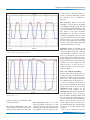
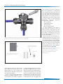
Trends in Level Measurement Technology
A Guide to Troubleshooting
PROFIBUS PA Networks
By James Powell, P.Eng.
A systematic approach makes network set-up and
troubleshooting easy and efficient
O
dd things are happening in the
process that you can’t explain.
Every so often, two of the pumps
turn on for no apparent reason. Or maybe
the red lights are flashing on the PLC.
Something’s wrong on the network
Whether you’re responding to a trouble signal or just starting up a new network, troubleshooting can be a difficult
process, particularly for the beginner;
however, a systematic approach can make
troubleshooting quite easy and even fun!
This article outlines a procedure for troubleshooting PROFIBUS PA, and identifies some of the tools required.
Network Challenges
Older, less robust networks will not work
at all if even one thing is incorrect. Like
a series set of Christmas tree lights, one
problem takes out the entire system.
PROFIBUS PA, on the other hand, is like
the set of parallel lights. It was designed
to continue operating even if a number of
things are wrong. This is a key strength
of the PROFIBUS network, but it also
poses some challenges. It means you
may not even know if there is a problem
on the network. If a PROFIBUS network
is not working, it probably means there is
more than one problem.
Tools Required
For PROFIBUS PA troubleshooting,
your tool kit should include:
• Screwdriver
• Multi-meter
• Copy of the PROFIBUS PA User
© 2004 Siemens Milltronics Process Instruments Inc.
Thorough, correct start-up is the key to trouble-free network operation.
and Installation Guideline (Version
2.2 Feb. 2003, order number 2.092)
• Oscilloscope (100 MHz or better)
• PROFIBUS Bus analyzer
Installing a New Network
Prevention is better than cure. Preventing
problems from the start is always better
than trying to fix them later. Thorough,
correct start-up is the key to trouble-free
operation for the future. There are three
key steps to ensuring correct installation.
First, before you begin implementing,
read the Profibus manual thoroughly. Then
follow the installation guidelines provided
www.siemens-milltronics.com
by the Profibus Trade Organization.
Second, ensure that all installation personnel know the wiring guidelines and know
how to use the wiring tools and connectors.
They say the three most common faults in
networks are wiring, wiring and wiring, so
paying attention to this aspect at the very
beginning will pay dividends by avoiding
problems later. Third, ensure that all
devices on the network have been certified.
After you have installed the wires, but
before you connect the devices, you
should perform a pre-startup wiring
check. The procedure is to remove the
connection to ground and then measure
1
Trends in Level Measurement Technology
Low Resistance
Between
Cause
PA+ and PA- or PA+ and
shield or PA- and shield
there is a short in a connector or wire
shield and ground
there is another spot where there is a
ground
Figure 1: This chart shows the cause of problems identified in a pre-startup wire check.
the resistance between each of the following: the PA+ lead, PA– lead, the
shield, and ground. At this point in the
setup, the resistance between all of these
should be infinite. If there is a low resistance between any of these, it indicates a
problem that must be corrected. Figure 1
summarizes the possibilities. A low
resistance between PA+ and PA– or PA+
and shield or PA– and shield indicates a
short in a wire or connector. Likewise, a
low resistance between PA+ or PA– and
ground also indicates a short in a wire or
connector. A low resistance between the
shield and ground indicates another spot
where you are connected to ground.
Another test you can do at this point is
to connect the PA+ and PA– at different
parts of the network and measure the
resistance at the start of the network. This
will indicate if you have a continuous loop
(i.e. low resistance). If you do not, then you
have a wire break somewhere in the loop.
Troubleshooting an Existing Network
If all the rules are followed in installing a
PROFIBUS PA network, then the network will work perfectly and no troubleshooting will be required. In reality,
you may be faced with troubleshooting
an existing network. If this is the case,
there is a lot you can do without being an
expert in the Profibus protocol. This is
because most network problems are
physical installation issues. These problems do not require in-depth network
knowledge, but they do entail a fair bit of
work to detect and correct. Taking a systematic, thorough approach will help you
be most efficient.
Step 1: Is it a Network Problem?
Given that PROFIBUS is robust network,
problems can manifest themselves in the
form of minor process problems. I have
heard statements like, “The system is
working fine, but there must be some sort
of tuning problem with the process,
because every so often, two of the pumps
will turn on for no apparent reason.” The
system may be working fine except for
this odd, unexplained event.
As a first step in your investigation,
check the diagnostic buffer on the PLC or
DCS. Check to see if any PROFIBUS
errors have been logged or if any stations
went missing off the network. This will
provide a good starting point, although it
may not tell the complete story. Some
network errors are minor enough that the
PROFIBUS Bus scanner may not report
them. In this case, it is best to connect a
bus monitor to the network and look for
PROFIBUS diagnostic requests. The
method for testing this will be discussed
in Step 3 below.
Once you know there is a problem, it is
just a matter of identifying it. Problems
are usually either Physical Layer problems or Device problems. Physical layer
Physical Layer Problems
• Bad termination
• Too many terminations
• Bad connections
• Bad grounding
• Insufficient power
• Network is too long
Device Problems
• Incorrect configuration
• Bad device
• Bad implementation of
PROFIBUS PA
problems include bad termination, too
many terminations, bad connections, bad
grounding, insufficient power, or a toolong network. Device problems include
incorrect configuration, malfunctioning
device, or bad implementation.
Step 2: Is the Physical Layer Working?
You can quickly tell if the physical layer
is working well by observing the waveform. To measure the waveform, place an
oscilloscope probe over an instrument’s
A and B PROFIBUS PA lines and set it
up for 20 micro seconds/div., and 200
mil-Volt/ div. (or depending on scope, hit
auto-setup).
Figure 2 shows an ideal waveform.
Figure 3 shows what the waveform will
look like with one missing terminator.
Notice that the voltage levels have
increased. If both terminators are missing, the peak-to-peak voltage will be even
higher.
If the waveform is completely distorted
with peak-to-peak voltages considerably
less than 800 mV, then you either have a
problem with low power or too many
devices. If you see strange spikes, you will
know something is not working correctly
or there is too much noise in the system.
If the waveform is fine, you know the
network problem is not in the physical
layer. It must be a problem either with the
connection to the device or with the
device itself. Sometimes, with grounding
issues and noise issues, the problems
may come and go; therefore, it is a good
idea to monitor the waveform for a period of time and also to measure it at more
than one point on the network.
Finding the source of the problem can
be very difficult and often requires you to
go over the entire network, checking each
device. This can be a laborious process,
but you can be most efficient by taking a
systematic approach. First, get a network
diagram. Then work from one end of the
network to the other, checking the wiring
and each device. Here are some suggestions for the most common problems.
Bad termination: Use the screwdriver to
tighten the terminator at the two far ends
of the network. If this does not fix it, get
2
Trends in Level Measurement Technology
nectors made by Siemens (Figure 4)
require a fair bit of tightening to make
the connection (use a screwdriver to
tighten it).
Bad grounding: When we say ‘bad
grounding,’ we mean either no grounding
or grounding in multiple points. This will
cause ground loops that will induce voltage on the network. The waveform will
have spikes or even other waveforms
superimposed on the ideal waveform.
Catching this problem with an oscilloscope can be difficult because the induced
voltages tend to vary over time. Finding
the cause of the ground loop means going
over the network and visually inspecting
each junction and how it is wired.
Figure 2: This ideal waveform indicates the device is communicating properly, with a peakto-peak voltage of approximately 800 mV.
Figure 3: This waveform indicates one missing terminator, with a peak-to-peak voltage of
approximately 1.5 V.
a new terminator (one that you know
works) and replace the terminators until
you find the bad one.
Too many terminations: This will
require going over the network from one
end to the other and trying to find where
the extra termination is.
Bad connections: This is one of the
hardest problems to find since it could
either be caused by a faulty part or by not
tightening the connector enough. Testing
the tightness is the first step. The con-
Insufficient power or network is too
long: First, check the power supply. If
the power supply is OK, refer to the User
and Installation Guidelines. You will
need to go through the process that the
design engineers used when they put the
system together, and calculate the power
requirements for that network and verify
that there are not too many devices. The
solution will be to move devices to
another network or to get a more powerful power supply.
Step 3: Are all Devices Working?
Always ensure that the physical layer is
good before trying to track down a device
problem. It is hard to tell a bad device
from a device that is simply having trouble communicating on a bad network.
For device problems, a bus monitor is
the best tool for figuring out what is happening on the network. If you are using
PROFIBUS DP/PA couplers, you can
connect the bus monitor on the
PROFIBUS DP side and watch the traffic
from that position. If you are using a
Siemens IM157 Profibus DP/PA Link,
then you will need to build a connector to
‘tap’ into the PA side of the Link module.
Figure 5 shows the pin-out of the connector required. Please note that this is
for troubleshooting only and should not
be left on the systems during normal
operation.
Once you are connected to the net-
3
Trends in Level Measurement Technology
Figure 4: Always ensure that the connectors are firmly tightened. This shows a Siemens
Profibus PA connector being tightened using a screwdriver.
Connect A line to pin 8 on DB-9
Connect B line to pin 3 on DB-9
DB-9 (Female)
Note: the wires from the coupler to the
DB-9 should be as short as possible
You can look at the device and verify
there is no application or configuration
error causing a repeated error. You can
also look at the returned diagnostic message and, using the device documentation, decode it to see what the slave is
complaining about. This will either point
you to the answer or deeper into troubleshooting.
Repeated
diagnostic
requests can be caused by:
• Device problem
• Application problem
• Set-up problem
• Device design problem
A device problem is the easiest to
solve since all you have to do is to
replace the device with another one. The
other three possible problems will probably require contacting the device vendor’s technical support for advice on how
to solve the problem.
Please note that the bus monitor is a
complicated program. To operate it best,
a good knowledge of the Profibus protocol is required. However, even a beginner
can get the bus monitor running and get
some traces that can be sent to a Profibus
expert for assistance. Please refer to
www.profibus.com for contact information about technical support. ■
James Powell, P.Eng, is Industry
Consultant, Communications Systems,
with Siemens Milltronics Process
Instruments Inc.
A
B
Figure 5: Wiring to tap into a Link/Coupler module
work, check the devices on the network
and compare that with the devices you
think should be on the network. The
function for checking this is called a Live
List on many programs.
Next, do a scan with the bus monitor
and look for DSAP (destination service
access point) of ‘3C’. This is a diagnos© 2004 Siemens Milltronics Process Instruments Inc.
tic request and should only occur at startup. If this is happening often to a slave,
there is a problem. As mentioned above,
a physical layer problem can cause this;
however, if you have already verified that
the physical layer is OK, then you have
to look closely at the device in question.
At this point, there are two approaches.
www.siemens-milltronics.com
4