1
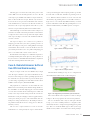
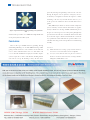
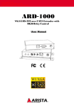
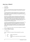
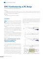
TROUBLESHOOTING
EMC Troubleshooting in PC Design
Lv feiyan, Cao Xin, Wang Liang Lenovo (Beijing) Co. Ltd.
Abstract
Two EMC cases in personal computer (PC) are presented, as one on conducted emission coupled from power port to
telecommunication port, the second one on radiated emission derived from poor ground in motherboard. The retrospect of debug and
analysis process is illuminated for system EMC design.
Keywords
EMC debug, PC, telecommunication port, grounding
Introduction
P
outer shield is coupled from the adapter, since the ground (GND)
of the adapter output DC terminal is grounded on the enclosure.
ersonal Computer (PC) is mostly used in office and home
The CE test result is ameliorated as shown in Figure 2. The final
environment, sometimes used as controlling center in
solution is some capacitances by-passed at the DC output circuit of
industry sites. Hence the EMC design for PC should
the adapter, as in Figure 3.
consider carefully the susceptible instruments surrounding, to
reduce the EMI as less as possible to meet Class B level per
CISPR 22[1].
PC is built up with CPU, memory, displaying unit and
peripherals. The peripheral, sub-assembly parts and motherboard
have compatibility issues in the design stage. Troubleshooting is
made in light of the whole system, as EMC design and analysis
should not impact the host performance.
This paper shares two cases in EMC design and debug in PC,
fallen into scope of conducted emission (CE) and radiated emission
(RE) respectively. Most of the contents are given to describe the
Figure 1 CE test result of telecommunication port of EUT
intricate process of detecting root cause, and of solution trying, to
illuminate the readers.
Case 1 - Conducted Emission from the
Power Port Coupling to the
Telecommunication Port
This case is of the influence of common mode CE from the power
port especially in the adapter, to the telecommunication port of the
host system [2].
In the CE test on telecommunication port, the result shows
Figure 2 CE test result of telecommunication port of EUT with reworked adapter
failure in the frequency band 3.8~4.5 MHz as Figure 1. The high
emission in this band is not influenced by the data rate and format
of telecommunication port. The frequency spectrum can be detected
with loop antenna at the DC output terminal of the power adapter.
Also the same spectrum can be detected on the outer shield of the
enclosure of EUT. It is proved that the outer surface current on the
30 SAFETY & EMC 2013 Figure 3 Circuit scheme of the re-worked power adapter of the EUT
TROUBLESHOOTING
The debug process is tortuous, due mostly to the perfect results
victim spectrum disappeared when replacing another type of CPU
of other EMC test items which disguised the root cause. The CE
heat sink. The new CPU heat sink differs in grounding means of
result of power port, and RE result of EUT are all passed. The only
screws. When the CPU heat sink has electrical connection with
failure is shown in CE of telecom port. Thus the early detection is
the fourth layer by grounding of the screws, the RE test failed, see
focused on the telecom port of the motherboard. Some solutions
Figure 4. So we can see that the dirty EMI on fourth layer is emitted
on the motherboard were tried, but in vain. Then the attention was
by means of the CPU heat sink. When the grounding of the screws is
transferred to the set-ups and peripherals of the CE test, yet the
insulated with the fourth layer, the EMI test passed, see Figure 5.
alternative tests proved that they had no relation with the failure.
The breakthrough occurred when another model of adapter was
used in the test and the result turned passed. The near field antenna
is employed to detect out the victim spectrum on the output terminal
of the suspected adapter, instead of on the motherboard. Thus the
real source is found.
The suspected adapter, once resulted in curve problem at
displaying port of the host system, has a grounding resistance of
10 Ω as R3 in Figure 3 at the protect earthing (PE) line of AC input
terminal. If this 10 Ω resistance is removed, the CE test of telecom
port will turn passed. However, the curve problem at displaying port
Figure 4 RE test result before solution
will re-occur. So this 10 Ω resistance can't be removed.
The final solution of C30 in Figure 3 is a combination of capacitances
of 1 000 pF and 470 pF. It will not impact any other performance of
the system. And we see that EMC solution should be the compromised
result when considering other functions of the system.
Case 2- Radiated Emission Suffered
from CPU Heat Sink Grounding
The process to figure out the root cause of EMI is always a tough
work. The engineer should be expert in the motherboard, not only
in layout such as routing, layer division, grounding split, but also in
Figure 5 RE test result after solution
The final solution including two steps, one is re-configuration of
the backboard of the CPU heat sink, as shown in Figure 6.
the craft. In this case, the layout scheme is perfect in the blue print,
yet a little change of grounding means of the CPU heat sink resulted
in EMI over limit at frequency band 800~900 MHz.
The peripherals are excluded since it's noticed that the victim
EMI is not derived from I/O ports of the EUT. During the RE test,
the victim EMI occurs when the displaying port is activated with full
screen of characters. Thus the data transferring between CPU and
memory card is suspected. The routing in Gerber file is checked to
find that there're four pairs of high speed lines for graphic function,
with 3 pairs running at top layer of the motherboard, while the
Figure 6 Re-configuration of the backboard of the CPU heat sink
The second is that the metal set up of the screw holes is changed
as Figure 7. The two steps guarantee the effect in mass production.
fourth pair is routing at the bottom layer. The fourth pair of lines is
The screw of CPU heat sink is only one small part of thermal
not grounded at GND, but on reference voltage port Udimm. Thus, the
design, yet its effect on EMI performance is magnified when
bottom layer is noisy.
stimulated by the little re-arrangement of grounding point in ground
The root cause is explored, but there's no time to return the
layer. This case reminds the R&D engineers that system design
motherboard to re-routing. Finally the engineer found that the
should concern beyond the circuit scheme to the realizing technique
SAFETY & EMC 2013 31
TROUBLESHOOTING
practically. Filtering and grounding is aimed at root cause. For
filtering, the magnetic coils or capacitance is frequency selective
so that many tests might be tried before the right one is found.
Grounding is the best way for both solution and cost, yet it
needs experienced estimation on where and with what means to
ground.
Many EMC analysis models are abstracted from complicated
system, with many elements omitted. Such models are popular
Figure 7 Improved metal set-up of the grounding screw of CPU heat
sink
details. It's the representative case in EMC that a slight modification
on one part may affect the whole system.
Conclusions
in many textbooks. Yet the magic of EMC troubleshooting lies in
the process of detecting root cause when passing through many
specious factors. Even the source is found, the solution is more than
one means. The engineer should consider both the cost and the
easy reproduction in mass. The final one is preferred that is costcontrolled and easily put into mass production in manufacturing
assembly.
There're three types of EMC solution as grounding, filtering
and shielding. Shielding is to cut off the EMI transferring, without
References
getting rid of the interference source from the root. So if the root
[1] cause is in the motherboard, the same over-limit failure will
re-occur when the motherboard is employed in another computer
CISPR 22 Information technology equipment-Radio disturbance
characteristics - Limits and methods of measurement[S].2008.
[2] Lv Feiyan, Caoxin, Zhou Hui. Influencing Factors in Conducted
system to require the second re-work. Besides, shielding material
Disturbance Test for Telecommunication Port According to GB 9254-
will result in cost-up. So shielding is always the last choice
2008[J], Safety & EMC,2009,4: 17-22.
32 SAFETY & EMC 2013