1
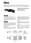
1. Controls / connections
1. Bedienteile/ Anschlüsse
CD Mark for adjustment of rotation angle
® Rotation-angle scale
@ Trip cams for limit valves
© Adjusting screws to limit angle of rotation
® Mounting holes
® Supply ports
CD Markierung für Drehwinkeleinstellung
® Drehwinkel-Skala
@ Schaltnocken tür Grenztaster
© Einstellschrauben für Drehwinkelbegrenzung
® Befestigungsbohrungen
® Druckluft-Anschlüsse
2. Technical data
2. Technische Daten
Part No. /Teile-Nr.
Type / Typ
[)._
[)._
[)._
[)._
[)._
[)._
0
0CO
0CO
0
ö
0
<k.
.;,
C\J
d:
(/)
N
0
.........
~ d:
"'(/)
~
N
..... 0
~
O>
'
C\J a:
"'(/)
"' Cl
~
O> '";0 a:
O>. (/)
0'
~ a:
O> (/)
O>
:::::: Cl
:::::: Cl
:::::: Cl
~
~
~
C\J
~
"'
a:'
O> (/)
~
:::::: Cl
Cl
Compressed air (filtered, lubricated or unlubricated) /
gefilterte, geölte oder gefilterte nicht geölte Druckluft
Medium
Design / Bauart
Rotary cylinder with rotary vane /Drehzylinder mit Schwenkflügel
Temperature range /
Temperaturbereich
-10 to ! bis +60 ' C
Operating pressure range /
Betriebsdruckbereich
2,5 to /
bis 8 bar
Mounting position / Einbaulage
Torque at 6 bar/
Drehmoment bei 6 bar
2 to/ bis 8 bar
1.5 to 8 bar / 1,5 bis 8 bar
any / beliebig
(Nm) 0,5
1
2
5
10
20
Permissible radial force
an drive shaft / zul. Radiallast auf Abtriebswelle
(N) 30
45
75
120
200
350
Permissible axial force an
drive shaft / zul. Axiallast
auf Abtriebswelle
(N) 10
18
30
50
75
120
0,3x10⁻⁴
0,6 x 10-•
0,9 x 10⁻⁴
1,4x 10- 4
2,0x10 -4
(kgm 2) 0,2 x1 0-4
Allowable mass
moment of inertia an the
drive shaft / Zulässiges
Massenträgheitsmoment
auf der Abtriebswelle