1
6 Set up the sensor with the display and adjustment module
6
6.1
Set up the sensor with the display and
adjustment module
Adjustment volume
The display and adjustment module is only used for parameter adjustment of the sensor, i.e. for adaptation to the measurement task.
The parameter adjustment of the Modbus interface is carried out via
aPCwithPACTware.Youcanfindtheprocedureinchapter"Set up
sensorandModbusinterfacewithPACTware".
6.2
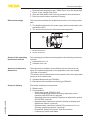
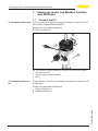
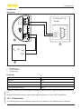
Insert display and adjustment module
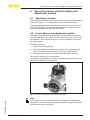
The display and adjustment module can be inserted into the sensor
andremovedagainatanytime.Youcanchooseanyoneoffourdifferent positions - each displaced by 90°. It is not necessary to interrupt
the power supply.
Proceed as follows:
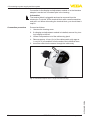
1. Unscrew the housing cover
2. Place the display and adjustment module in the requested position onto the electronics and turn to the right until it snaps in
3. Screw housing cover with inspection window tightly back on
Removal is carried out in reverse order.
The display and adjustment module is powered by the sensor, an additional connection is not necessary.
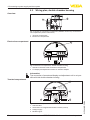
41363-EN-140210
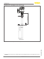
Fig. 10: Insertion of the display and adjustment module
Note:
Ifyouintendtoretrofittheinstrumentwithadisplayandadjustment
module for continuous measured value indication, a higher cover with
an inspection glass is required.
VEGAPULS 62 • Modbus and Levelmaster protocol
21