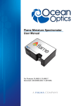
1
Deuterium-Halogen Light Source DH-2000 / DH-2000-BAL / DH-2000-DUV / DH-2000-S / DH2000-S-DUV / DH-2000-FHS, DH-2000-FHS-DUV / DH-2000-S-DUV-TTL A Product Installation and Operation Manual Document Number 000-10000-025-02-1105 Offices: Ocean Optics, Inc. 830 Douglas Ave., Dunedin, FL, USA 34698 Phone 727.733.2447 Fax 727.733.3962 8 a.m.– 8 p.m. (Mon-Thu), 8 a.m.– 6 p.m. (Fri) EST Ocean Optics B.V. (Europe) Geograaf 24, 6921 EW DUIVEN, The Netherlands Phone 31-(0)26-3190500 Fax 31-(0)26-3190505 E-mail: [email protected] [email protected] [email protected] [email protected] (General sales inquiries) (European sales inquiries) (Questions about orders) (Technical support) Protective Eye Wear Must Be Worn When Using This Instrument Intense Ultraviolet Radiation Present WARNING See Important Safety Notices inside. Ocean Optics offers the most comprehensive, innovative and high-quality line of modular spectroscopy tools in the world. Mikropack, a leading supplier of spectroscopy and thin film components, is an essential and valuable partner in this enterprise. We have partnered with Mikropack because they are committed to the same goals of innovation and quality that inspire us here at Ocean Optics. As always, Ocean Optics conducts its business in an open, honest and technically available fashion. We invite you to contact us at Ocean Optics, Inc. (see front cover for contact information) or Mikropack GmbH with any technical questions, comments, or applications inquiries. Mikropack GmbH can be contacted at the following location: MIKROPACK GmbH Maybachstraße 11 D-73760 Ostfildern Germany Tel.: +49 (0)711 34 16 96-0 • Fax.: +49 (0)711 34 16 96-85 e-mail: [email protected] internet: www.mikropack.de Copyright © 2001-2005 Ocean Optics, Inc. All rights reserved. No part of this publication may be reproduced, stored in a retrieval system, or transmitted, by any means, electronic, mechanical, photocopying, recording, or otherwise, without written permission from Ocean Optics, Inc. This manual is sold as part of an order and subject to the condition that it shall not, by way of trade or otherwise, be lent, re-sold, hired out or otherwise circulated without the prior consent of Ocean Optics, Inc. in any form of binding or cover other than that in which it is published. Trademarks Microsoft, Windows, Windows 95, Windows 98, Windows Me, Windows NT, Windows 2000, Windows XP and Excel are either registered trademarks or trademarks of Microsoft Corporation. Limit of Liability Every effort has been made to make this manual as complete and as accurate as possible, but no warranty or fitness is implied. The information provided is on an “as is” basis. Ocean Optics, Inc. shall have neither liability nor responsibility to any person or entity with respect to any loss or damages arising from the information contained in this manual. Important Safety Notices 1. Do not remove or modify any installed safety device on this equipment. Doing so will void your warranty and create an unsafe operating environment. 2. Dangerous voltages are present in this device. There are NO user serviceable parts inside. 3. Only allow qualified personnel to service this unit. 4. Do not use the unit if it is damaged in any way. Contact your dealer for repair or replacement information. 5. Always screw in the fiber optic cables before starting the instrument. WARNING Protective eyewear must be worn when using this equipment - Intense ultraviolet radiation present. Never look directly into the light beam, as this can cause eye damage. Warranty Mikropack GmbH warrants to the original user of this instrument that it shall be free of any defects resulting from faulty manufacture of this instrument for a period of 12 months from the original data of shipment. This instrument should not be used for any Clinical or Diagnostic purposes. Data generated in these areas is not warranted in any way by Mikropack GmbH. Any defects covered by this Warranty shall be corrected either by repair or by replacement, as determined by Mikropack GmbH. There are no warranties that extend beyond the description herein. This Warranty is in lieu of, and excludes, any and all other warranties or representations expressed, implied, or statutory, including merchantability and fitness, as well as any and all other obligations or liabilities of Mikropack GmbH including, but not limited to, special or consequential damages. No person, firm, or corporation is authorized to assume for Mikropack GmbH. Any additional obligation or liability not expressed provided for herein except in writing duly executed by an officer of Mikropack GmbH: MIKROPACK GmbH Maybachstraße 11 D-73760 Ostfildern Tel.: +49 (0)711 34 16 96-51 • Fax.: +49 (0)711 34 16 96-85 e-mail: [email protected] internet: www.mikropack.de 000-10000-025-02-1105 A Important Safety Notices B 000-10000-025-02-1105 Table of Contents About This Manual .......................................................................................................... iii Document Purpose and Intended Audience .............................................................................. iii What’s New in this Document.................................................................................................... iii Document Summary .................................................................................................................. iii Product-Related Documentation................................................................................................ iii Upgrades ......................................................................................................................... iv Chapter 1: Setup .................................................................................1 Overview.......................................................................................................................... 1 Unpacking the DH-2000 .................................................................................................. 2 Contents .......................................................................................................................... 2 Connecting the Fiber Optic Cable ................................................................................... 2 Chapter 2: DH-2000 Specifications ....................................................5 Operating Environment.................................................................................................... 5 DH-2000 Components..................................................................................................... 5 Front Panel ................................................................................................................................ 6 Rear Panel................................................................................................................................. 7 Specifications .................................................................................................................. 8 Pinout Information ........................................................................................................... 9 15-pin Connector Pinout Diagram ................................................................................... 9 Chapter 3: Operating Instructions .....................................................11 Operating the Lamp......................................................................................................... 11 Starting the Lamp ...................................................................................................................... 11 Turning the Lamp Off................................................................................................................. 11 Warming Up the Lamp............................................................................................................... 12 000-10000-025-02-1105 i Table of Contents Chapter 4: Troubleshooting ...............................................................13 Deuterium Lamp .............................................................................................................. 13 Halogen Lamp ................................................................................................................. 14 Appendix A: Maintenance ..................................................................15 Overview.......................................................................................................................... 15 Bulb Replacement ........................................................................................................... 15 Replacing the Deuterium Bulb for All Models Except DH-2000-BAL......................................... 16 Replacing the Deuterium Bulb for DH-2000-BAL Model............................................................ 16 Replacing the Halogen Bulb for All Models Except DH-2000-BAL ............................................ 18 Replacing the Halogen Bulb for DH-2000-BAL Model............................................................... 19 Appendix B: Supplementary Information for Models DH-2000-S and DH-2000-FHS .......................................................................................21 Overview.......................................................................................................................... 21 DH-2000-S (With TTL Shutter Control) ........................................................................... 21 Automatic Operation .................................................................................................................. 21 Manual Operation ...................................................................................................................... 21 DH-2000-FHS (With Filter Holder and TTL Shutter Control) and DH-2000-BAL............. 22 TTL Function Operating Instructions ......................................................................................... 22 Operating Instructions – Filter (DH-2000-FHS Only) ................................................................. 22 Index.....................................................................................................25 ii 000-10000-025-02-1105 About This Manual Document Purpose and Intended Audience This document provides you with an installation section to get your system up and running. What’s New in this Document This version of the Deuterium-Halogen Light Source DH-2000 / DH-2000-BAL / DH-2000-DUV / DH-2000-S / DH-2000-S-DUV / DH-2000-FHS, DH-2000-FHS-DUV / DH-2000-S-DUV-TTL Installation and Operation Manual updates TTL shutter information. Document Summary Chapter Description Chapter 1: Setup Contains a list of package contents and unpacking instructions. Chapter 2: DH-2000 Specifications Contains operating environment specifications, as well as other physical details of the product. Chapter 3: Operating Instructions Provides instructions for operating the DH-2000 Light Source. Chapter 4: Troubleshooting Contains troubleshooting information for the power supply and both the deuterium and halogen lamps. Appendix A: Maintenance Provides instructions for changing the bulb. Appendix B: Supplementary Information for Models DH-2000-S and DH-2000-FHS Contains operating instructions specific to the DH-2000-S and DH-2000-FHS models. Product-Related Documentation You can access documentation for Ocean Optics products by visiting our website at http://www.oceanoptics.com. Select Technical → Operating Instructions, then choose the appropriate document from the available drop-down lists. Or, use the Search by Model Number field at the bottom of the web page. You can also access operating instructions for Ocean Optics products on the Software and Technical Resources CD included with the system. Engineering-level documentation is located on our website at Technical → Engineering Docs. 000-10000-025-02-1105 iii About This Manual Upgrades Occasionally, you may find that you need Ocean Optics to make a change or an upgrade to your system. To facilitate these changes, you must first contact Customer Support and obtain a Return Merchandise Authorization (RMA) number. Please contact Ocean Optics for specific instructions when returning a product. iv 000-10000-025-02-1105 Chapter 1 Setup Overview The following sections provide instructions on unpacking and setting up your DH-2000 Light Source. Before using the DH-2000 for the first time check for transport damage. Be sure to adhere to all warnings on the unit and in this manual. 000-10000-025-02-1105 1 1: Setup Unpacking the DH-2000 ► Procedure 1. Unpack your lamp assembly and power supply carefully. Although the lamp is rigidly mounted, dropping this instrument can cause permanent damage. 2. Inspect the outside of the instrument and make sure that there is no damage. Do not use the instrument if damage is present. 3. Use this instrument in a clean laboratory environment (see Operating Environment). Contents Your DH-2000 package should contain the following: DH-2000 unit Power cord One IC-DB15-2 interface cable for shutter operation (DH-2000-S, DH-2000-BAL, DH-2000FHS, DH-2000-S-DUV-TTL, and D-2000-S models only) UV safety goggles Connecting the Fiber Optic Cable Use the following procedure to connect the cable to the lamp. 2 000-10000-025-02-1105 1: Setup ► Procedure To connect the fiber optic cable to the DH-2000, 1. Locate the cap on the front of the DH-2000. 2. Lift the cap on the front of the DH-2000 to expose the SMA connector. 3. Connect the fiber optic cable to the SMA connector. 000-10000-025-02-1105 3 1: Setup 4 000-10000-025-02-1105 Chapter 2 DH-2000 Specifications This section provides information on the operating environment, physical controls, and dimensions of the DH-2000. Operating Environment The following table provides information on optimizing the operating environment of your DH-2000 unit. Operating Environment The DH-2000 Unit . . . Moisture Is designed for operation in dry rooms only. Ventilation Should be situated so that its location or position does not interfere with proper ventilation. Heat Should be situated away from any device that emits excessive heat. Object and Liquid Entry Should be positioned so that objects do not fall on top of the unit. Additionally, ensure that no liquids are spilled into the enclosure through openings. Power Sources Should be connected to a power supply with the following specifications: • Units manufactured since April 2003 are equipped with power supplies that can handle voltage input of 90 to 240 VAC. These units have a serial number formatted as 23XXXX. • Units manufactured before April 2003 are equipped with power supplies that can handle either 110 VAC or 240 VAC. These units have serial numbers formatted as 02000XXX. The power type should be listed on a sticker on the rear of the light source. DH-2000 Components The following sections describe the components located on the front and rear of the DH-2000 unit. Also see Supplementary Information for Models DH-2000-S and DH-2000-FHS if you have one of these models. 000-10000-025-02-1105 5 2: DH-2000 Specifications Front Panel Halogen On/Off Mechanical Protection –SMA Connector Deuterium On/Off TTL Shutter On/Off Switch Power LED Component Description Deuterium On/Off Press to turn the Deuterium lamp on or off. The bulb requires a warm-up time of 20 seconds before the Deuterium lamp is illuminated. You must allow the bulb to warm up to receive accurate data from the lamp. LED lights green upon successful illumination, or red to indicate lamp malfunction. Power LED Indicates the power state of the DH-2000. Mechanical Protection – SMA Connector Covered to protect users from unintentionally looking directly at the beam of light. Connect the fiber cable to the DH-2000 BEFORE turning the lamp on to avoid unnecessary exposure to UV radiation. Always wear proper eye protection when using the DH-2000 lamp. Halogen On/Off Press to turn the Halogen lamp on or off. Requires a warm-up time of 20 seconds before the Halogen lamp is illuminated. LED lights green upon successful illumination, or red to indicate lamp malfunction. For DH-2000-S and -BAL models: Shutter Mode Switch 6 Sets the operational mode of the shutter. Open indicates that the shutter is constantly open; Closed indicates that the shutter is constantly closed; TTL indicates that the shutter is operated via 5V TTL signal (see Rear Panel). 000-10000-025-02-1105 2: DH-2000 Specifications Rear Panel Variable Resistor Cooling Fan Type Sign Main Power Switch Fuse Power Terminal Input Component Variable Resistor Description Use a screwdriver to adjust the intensity of the halogen lamp to optimize the intensity between deuterium and halogen light in UV-VIS applications. DH-2000-(S)-(FHS)-(DUV)-(BAL) Halogen Adjustment Voltage 5V - 12 V Optical Power 10% - 100% Connect power cable to provide voltage to DH-2000: Power Terminal Input Main Power Switch Note: Only connect the power cable to the lamp when the Main Power Switch is in the OFF position. Turn on to supply power to the DH-2000. The Power LED illuminates when this switch is in the On position. Contains the fuse to protect the unit against overload: Fuse European Fuse Type: Miniature fuse 5 x 20 mm, 1 Amp slow blow USA Fuse Type: Miniature fuse 5 x 20 mm, 2.5 Amp slow blow Cooling Fan Cools the interior of the DH-2000. Do not obstruct. Information about: Type Sign – Type – Version – Order No. – Serial No. – Main connection – Max. Ambient. Temperature – Warnings 15-pin TTL Connector (not shown) 000-10000-025-02-1105 – CE-Marking On TTL Connector-equipped DH-2000 Series lamps, this connector allows for external TTL control of lamp shuttering (-S and _BAL models only) and individual lamp operation (TTL model only). See Pinout information. 7 2: DH-2000 Specifications Specifications Specifications Deuterium Lamp Criteria Tungsten-Halogen Lamp Criteria Wavelength Range 210–400 nm 300–1500 nm Current – Voltage – Stability ≤0,01 % / h 0.4% of voltage Current – Voltage – Drift ≤0,01 % / h Warm-Up Time 20 minutes 40 minutes Lamp Voltage Ignition 580V / 20° 12V DC / 1.67A Lamp Current Operating 85 V / 0.3A Lamp Lifetime Radiation Characteristics 1000 hours Aperture 0.5mm NA26° (13°) Focused PIN Position at SUB-D 15 Pin Connector (Only -S / -FHS / -BAL models) Shutter PIN 13: TTL / PIN 10: Ground (Only -TTL model) PIN 2 Deuterium / PIN3 Halogen / PIN 4 Ground Possible Filter Dimensions (only -FHS model) Up to diameter or square 25mm x 4mm, or 20mm x 6mm Performance Guaranteed Temperature 5°C – 35°C Humidity Internal Power Consumption Total Power Max. Power Consumption 5 - 95% without condensation at 40° 25 W 20 W 100 Watt/190 Watt (Heating D-Lamp for 20 seconds) Power Requirements: European Version (prior to 4/2003) 230-240V 50/60 Hz USA Version (prior to 4/2003) 110-115V 50/60 Hz All units manufactured after 4/2003 90-240V 50/60 Hz See Operating Environment for specific information. Markings / Directives 8 CE; VDI/VDE 0160; EN 61010 Weight Approximately 6 kg Size 150 x 135 x 319 mm 000-10000-025-02-1105 2: DH-2000 Specifications Pinout Information The following table contains pinout information for the DH-2000 Series of Lamps. Consult the appropriate column for pinout information on your lamp. Description 1 na 2 Deuterium Lamp – Turns the Deuterium Lamp on when 5V is applied to the pin X 3 Halogen Lamp - Turns the Halogen Lamp on when 5V is applied to the pin X 4 Ground (TTL versions only) X 5 na 6 na 7 na 8 na 9 na 10 Ground 11 na 12 na 13 TTL Signal – Shutter control 14 na 15 na DH-2000 Pin DH-2000-BAL DH-2000-TTL DH-2000-FHS DH-2000-S If your lamp is not listed, pinout information in this chart is not applicable for your particular model. X X X X X X X X X X na = not applicable 15-pin Connector Pinout Diagram 000-10000-025-02-1105 9 2: DH-2000 Specifications Note Modification of specifications and design to improve device performance are possible without notice. 10 000-10000-025-02-1105 Chapter 3 Operating Instructions Operating the Lamp The following sections provide instructions on operating the Deuterium and Halogen lamps in the DH2000. The Halogen lamp is only available in the DH-2000, DH-2000-DUV, and DH-2000-BAL models. Caution The unit must operate in a horizontal position. Starting the Lamp Press the Deuterium or Halogen On/Off switch down to preheat the desired lamp. The LED blinks green until the lamp illuminates (approximately 20 seconds). The bulb requires a 20-second preheating period. You must allow this warm up period in order to receive accurate data. After the warm up period, the lamp will light. After successful illumination, the two-color LED beneath the lamp’s On/Off switch lights up green to indicate that the lamp is on. Should the lamp fail to light, the two-color LED lights up red. This indicates a malfunction of the lamp. Press the On/Off switch again to reset the lamp. See Troubleshooting for more information. Protective eyewear must be worn when using this equipment - Intense ultraviolet radiation present. WARNING Never look directly into the light beam, as this can cause eye damage. Turning the Lamp Off Turn the lamp off by pressing the appropriate On/Off switch. 000-10000-025-02-1105 11 3: Operating Instructions Warming Up the Lamp The Deuterium lamp requires 10–15 minutes, while the Tungsten-Halogen lamp requires 5–10 minutes of operation to reach a state of thermal equilibrium. During this warm-up period, the intensity of the UV output power can vary substantially. If applications require extreme intensity stability, the Halogen lamp should be warmed up for an additional 15 minutes. Once warmed up for this amount of time, the lamp will reach specified drift values. 12 000-10000-025-02-1105 Chapter 4 Troubleshooting Deuterium Lamp If the power supply or Deuterium lamp does not seem to functioning properly, check the following: Issue Probable Cause Resolution Power switches on, but no LEDs light. Line power not present Check line voltage Fuse defective Check fuse Allow the Deuterium lamp to cool down (20 minutes). Deuterium lamp does not light. The two-color LED under the Deuterium On/Off switch lights up red, indicating an error. Deuterium lamp too hot Press On/Off switch again to reset the Deuterium TungstenHalogen lamp, then press again to restart. Deuterium lamp life exhausted Replace Deuterium lamp Deuterium lamp’s internal connection plug is not closed correctly. Open unit (see the Maintenance) and close connector plug. Turn off the unit. Deuterium lamp turns off during operation. Deuterium lamp too hot Allow the unit to cool down for at least 20 minutes. Once the unit has cooled down, turn the Deuterium lamp back on. 000-10000-025-02-1105 13 4: Troubleshooting Halogen Lamp If the Halogen lamp does not seem to functioning properly, check the following: Issue Probable Cause Resolution Halogen lamp does not work after pressing On/Off switch Deuterium lamp is warming up Wait until the Deuterium lamp has lit and try again Halogen lamp is defective Replace the Halogen lamp LED does not light after switching on the Halogen lamp Internal power supply is defective Disconnect the unit from the main power source and contact your dealer for repair or replacement 14 000-10000-025-02-1105 Appendix A Maintenance Overview Maintenance of your DH-2000 unit involves periodic replacing the light source bulbs, when necessary. Bulb Replacement You can manually change the Deuterium and Halogen bulbs in the DH-2000. To order replacement bulbs for the DH-2000, order the following item number(s): • Deuterium Spare Bulb (210 – 400 nm): D-2000-B • Deuterium Spare Bulb Deep UV (190 – 400 nm): D-2000-B-DUV • Halogen Spare Bulb (300 – 1500 nm): DH-2000-B WARNING Before replacing the bulb in the DH-2000, disconnect the lamp from your power source and allow the unit to cool for at least twenty minutes, if necessary. Do not touch the lamp glass directly, as contact with bare fingers will reduce the lifetime of the bulb. 000-10000-025-02-1105 15 A: Maintenance Replacing the Deuterium Bulb for All Models Except DH2000-BAL ► Procedure 1. Open the six slotted screws (14) and open the casing cover. 2. Open the screws (15) with the tool (18) that is delivered with the spare bulb (16). 3. Disconnect the old bulb and connect the new Deuterium Tungsten-Halogen lamp only with the originally supplied connection plugs (17). Replacing the Deuterium Bulb for DH-2000-BAL Model ► Procedure 1. Open the six slotted screws (14) and open the casing cover and rotate or remove the cover to expose the bulb housing. 16 000-10000-025-02-1105 A: Maintenance 2. Open the screws (15) with the tool (18) that is delivered with the spare bulb (16). 3. Disconnect the old bulb and connect the new Deuterium lamp only with the originally supplied connection plugs (17). 4. Reassemble the lamp housing by reversing Steps 1-3. 000-10000-025-02-1105 17 A: Maintenance Replacing the Halogen Bulb for All Models Except DH-2000-BAL ► Procedure 1. Open the six slotted screws (14) and open the casing cover. 2. Remove the screw (21) with the tool (20) provided with the spare bulb (19). 3. Disconnect the old Halogen bulb from the connection plugs (18) 4. Open the screws of the cable-clamp on the lamp-side and remove the defective Halogen lamp module. 5. Insert the new Halogen lamp module and Replace the screw (21). 18 000-10000-025-02-1105 A: Maintenance 6. Reattach the two cables of the Halogen lamp module to the cable-clamp. To do this, attach the Halogen lamp’s blue cable to Port 1 and the black cable to Port 2 of the connector. Replacing the Halogen Bulb for DH-2000-BAL Model ► Procedure 1. Open the six slotted screws (14) and open the casing cover. 2. Remove the screw (21) with the tool (20) provided with the spare bulb (19). 3. Disconnect the old Halogen bulb from the connection plugs (18) 4. Open the screws of the cable-clamp on the lamp-side and remove the defective Halogen lamp module. 000-10000-025-02-1105 19 A: Maintenance 5. Insert the new Halogen lamp module and Replace the screw (21). 6. Reattach the two cables of the Halogen lamp module to the cable-clamp. 7. Reassemble the unit by reversing the disassembly steps. 20 000-10000-025-02-1105 Appendix B Supplementary Information for Models DH-2000-S and DH-2000-FHS Overview The following information applies to specific models of the DH-2000. Read the instructions and refer to the figures on page 23. DH-2000-S (With TTL Shutter Control) Automatic Operation Plug SUB-D 15-pin TTL connector into socket on rear of DH-2000-S. Manual Operation Manually set operating mode using the toggle switch on the front of the DH-2000-S: • Open - Shutter open • Close - Shutter closed • TTL - Controls shutter with external TTL signal (High = Open, Low = Close) 000-10000-025-02-1105 21 B: Supplementary Information for Models DH-2000-S and DH-2000-FHS DH-2000-FHS (With Filter Holder and TTL Shutter Control) and DH-2000-BAL TTL Function Operating Instructions Automatic Operation Plug the SUB-D 15-pin TTL connector into the socket on the rear of the DH-2000-FHS. Manual Operation Manually set operating mode using the toggle switch on the front of the DH-2000-FHS: • Open - Shutter open • Close - Shutter closed • TTL - Controls shutter with external TTL signal (High = Open, Low = Close) Operating Instructions – Filter (DH-2000-FHS Only) ► Procedure 1. Open the filter slit by rotating the light beam protection cap. 2. Insert a filter with a maximum size of 1” (round or square) into the filter slit. 3. Close the filter slit by rotating the light beam protection cap until the slit is closed. 22 000-10000-025-02-1105 B: Supplementary Information for Models DH-2000-S and DH-2000-FHS Switch 000-10000-025-02-1105 Light Beam Protection Filter Slit SUB-D 15 Pin TTL Connector 23 B: Supplementary Information for Models DH-2000-S and DH-2000-FHS 24 000-10000-025-02-1105 Index B bulb replacement, 15 deuterium bulb, 16 deuterium bulb for DH-2000-BAL, 16 halogen bulb, 18 halogen bulb for DH-2000-BAL, 19 C components, 5 front panel, 6 rear panel, 7 connecting fiber optic cable, 2 D document audience, iii purpose, iii summary, iii maintenance, 15 Model DH-2000-FHS automatic operation, 22 filter instructions, 22 manual operation, 22 operating instructions, 22 Model DH-2000-S automatic operation, 21 manual operation, 21 O operating environment, 5 operating instructions, 11 lamp, 11 P L lamp starting, 11 turning off, 11 warming up, 12 M package contents, 2 product-related documentation, iii S setup, 1 specifications, 5 specifications table, 8 T troubleshooting deuterium lamp, 13 halogen lamp, 14 troubleshooting table, 13 TTL shutter control, 21 000-10000-025-02-1105 25 Index U unpacking procedure, 2 upgrades, iv 26 W warranty, A what's new, iii 000-10000-025-02-1105