1
RO(L)
Installation Manual
Old Number Manual M96103
Kollmorgen Motion
Technologies Group
July 1996
New Number MRO000H
RO(L)
Installation Manual
Manual 96103
Kollmorgen Motion Technologies Group
201 Rock Road
Radford, VA 24141
July 1996
(c) Copyright 1996, Kollmorgen Corporation. All rights reserved.
Printed in the United States of America.
NOTICE:
Not for use or disclosure outside of Kollmorgen Corporation.
All rights reserved. No part of this book shall be reproduced, stored in a retrieval system, or transmitted by
any means, electronic, mechanical, photocopying, recording, or otherwise without written permission from
the publisher. While every precaution has been taken in the preparation of this book, the publisher assumes
no responsibility for errors or omissions. Neither is any liability assumed for damages resulting from the
use of the information contained herein.
This document is proprietary information of Kollmorgen Corporation and furnished for customer use
ONLY. No other uses are authorized without written permission of Kollmorgen Corporation.
Information in this document is subject to change without notice and does not represent a commitment on
the part of Kollmorgen Corporation. Therefore, information contained in this manual may be updated from
time-to-time due to product improvements, etc. and may not conform in every respect to issues.
NEC is a trademark of the National Electric Code.
KOLLMORGEN SILVERLINE, RBE, RO, and ROL Amplifier are trademarks of the Kollmorgen
Corporation.
WARNING
Dangerous voltages, currents, temperatures, and
energy levels exist in this product and in the
associated servo motor(s). Extreme caution should
be exercised in the application of this equipment.
Only qualified individuals should attempt to install,
set-up, and operate this equipment. Ensure that the
motor, amplifier, and the end-user assembly are all
properly grounded and current limited per NEC
requirements.
European Community (EC) Declaration of Conformity
We, Kollmorgen Corporation Industrial Drives Division,
201 Rock Road, Radford, Virginia USA; declare under sole
responsibility that this equipment is exclusively designed
for incorporation in another machine. The operation of this
equipment is submitted to the conformity of the machine in
which it is incorporated, following the provisions of the EC
Electro-Magnetic Compatibility (EMC) directive
89/392/EEC.
RO(L) INSTALLATION MANUAL
TABLE OF CONTENTS
TABLE OF CONTENTS
CHAPTER 1
SYSTEM DESCRIPTION
1
INTRODUCTION
1
PART NUMBER DESCRIPTION
RO(L) Model Number
1
2
SPECIFICATIONS AND RATINGS
2
CHAPTER 2
MOUNTING AND WIRING
7
INTRODUCTION
7
SAFETY INFORMATION
7
UNPACKING AND INSPECTION
8
INSTALLATION REQUIREMENTS
Environmental Considerations
Ventilation
Minimum Inductance Requirement
Noise and System Grounding
8
8
8
8
8
MOUNTING
9
MOUNTING THE FAN
9
WIRING OVERVIEW
Strain Relief
Motor Protection
Bus Capacitor (RO Only)
Regeneration
Motor Cable
9
9
10
10
10
11
WIRING THE ENCODER
11
WIRING THE AMPLIFIER
Wiring JL, Line Cord (ROL only)
Wiring J1, Bus Power and Motor Leads
Wiring J6, Amplifier Status and Control
Wiring J9, Encoder
Switch SW1
12
12
12
15
15
15
CHAPTER 3
CHECK OUT AND COMMISSIONING
START UP AND CHECK OUT
Mode Selection
Start up the Current/Open Loop Controller
Start up the Velocity Controller
23
23
23
25
28
v
TABLE OF CONTENTS
RO(L) INSTALLATION MANUAL
Velocity Loop Tuning
Troubleshooting
28
29
STABILITY AND PERFORMANCE
Critical Damping
Underdamping
Overdamping
Ringing
30
30
30
31
31
ADVANCED CURRENT LOOP TUNING
Theory of Operation
Measurement and Control
31
31
32
VELOCITY LOOP PROBLEMS
Compliance
Non-Linearities
Resonance
33
33
33
33
EMPIRICAL METHOD: PHASING NON-KOLLMORGEN MOTORS
34
CHAPTER 4
MAINTENANCE
35
INTRODUCTION
35
SPARE PARTS
35
PREVENTATIVE MAINTENANCE
Transient Voltages
Electrical Noise
Radio Frequency Energy
35
36
36
36
PERIODIC MAINTENANCE
Grounding Integrity
36
36
APPENDIX A
WARRANTY INFORMATION
37
APPENDIX B
OUTLINE DRAWINGS
39
APPENDIX C REGIONAL SALES OFFICES
45
SOUTHERN REGION
46
EASTERN REGION
46
MIDWEST REGION
46
WESTERN REGION
46
INTERNATIONAL
46
INDEX
vi
47
RO(L) INSTALLATION MANUAL
TABLE OF CONTENTS
LIST OF TABLES
Table 1.1 Specifications
3
Table 1.2 Velocity Loop
3
Table 1.3 Integral Power Supply Specifications (ROL Only)
4
Table 1.4 Environmental Specifications
4
Table 1.5 Mechanical Specifications*
4
Table 2.1
Silverline Encoder
11
Table 2.2
Connector J1: Power
12
Table 2.3 Connector J6
13
Table 2.4 Connector J9
15
Table 2.5 SW1 Settings
16
Table 2.6 RO(L) Connector Function
16
Table 3.1 SW1 Settings: Non-Velocity Control
25
Table 3.2 SW1 Settings: Velocity Control
28
vii
TABLE OF CONTENTS
RO(L) INSTALLATION MANUAL
LIST OF FIGURES
Figure 1.1 RO(L) Model Number Scheme
2
Figure 1.2 Block Wiring Diagram for ROL and RO Amplifiers
5
Figure 1.3 ROL System Wiring Diagram, Velocity Loop Mode
6
Figure 2.1 Capacitive Coupling
9
Figure 2.2 Silverline Encoder
17
Figure 2.3 RO(L) Connector Layout--Main PCB
18
Figure 2.4 Connectors J1 and J6 for SILVERLINE/RBE Motors
19
Figure 2.5 Connector J6 Amplifier Enable, Command and Status
20
Figure 2.6 Connector J9 Feedback Encoder (Velocity Loop Mode Only)
21
Figure 3.1 Control Loop Function Diagram
24
Figure 3.2 Critical Damping
30
Figure 3.3 Underdamping
30
Figure 3.4 Overdamping
31
Figure 3.5 Ringing
31
Figure 3.6 -3dB Point: 70% Attenuation
32
Figure B.1 ROL Series Outline
40
Figure B.2 RO Series Outline
41
Figure B.3 Fan Bracket RO(L)-20012 Only
42
Figure B.4 Size 23 Outline
43
Figure B.5 Size 34 Outline
44
viii
RO(L) INSTALLATION MANUAL
CHAPTER 1 - SYSTEM DESCRIPTION
CHAPTER 1
SYSTEM DESCRIPTION
INTRODUCTION
The Kollmorgen RO(L)-series amplifiers are six-step
modules designed to bring high performance to costsensitive applications. RO(L) amplifiers have these
important features:
•
•
•
•
•
•
•
•
•
Small package
Direct 115 VAC line operation (ROL only)
Integral regen dissipation unit (ROL only)
High linearity
Differential ±10 volt input
User selectable operation modes:
High performance current loop mode
Open loop mode
Velocity loop mode
Switch selectable 60° or 120° commutation
Over-current protection
Over-voltage protection
•
•
•
•
Continuous current limit
Fully heat-sinked
Up to 190 VDC input for RO
Up to 130 VAC input for ROL
Up to 12 amp continuous (25 amp peak) output
This manual provides information for installation and
operation.
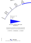
PART NUMBER DESCRIPTION
A model number is printed on a tag on the top of your
RO(L). The model number identifies how the
equipment is configured. Each component is
described in Figure 1.1. Verify that the model
numbers represent the equipment required for your
application.
1
CHAPTER 1 - SYSTEM DESCRIPTION
RO(L) INSTALLATION MANUAL
RO(L) Model Number
R O (L) - 200 04
- 0000
R eserved
0000 - S tandard
R O A n alog
A m plifier
R O L A nalo g A m plifier
L in e O perated
Inp ut V o ltage
200 - (135-190 V D C , R O only)
200 - (90-130 V A C , R O L only)
C o ntin uou s O utp ut C u rrent
04 - 4 A D C *
12 - 12 A D C
*ADC refers to DC Amps. This unit is used on six-step systems to indicate the current in the two motor leads which
are enabled (in six-step, one lead is always open circuit). 1 ADC = 1/1.22 amps RMS/Phase.
Figure 1.1 RO(L) Model Number Scheme
SPECIFICATIONS AND RATINGS
Specifications Control Outputs
Level)
AMP OK (TTL
Current Overload
Monitor RMS Current
ANALOG INPUT
Type
Impedance,
ANALOG INPUT
Full Differential, ±10 volts
Maximum Current
for AMP OK
(sink only)
20 mA
Voltage Range for
AMP OK
TTL (5 ±10%)
2
IMonitor
1V = 1.33 ADC RO(L) - 20004
1V = 4.00 ADC RO(L) - 20012
Control Inputs
ANALOG-CMD (Analog)
ENABLE' (TTL Level)
Control Method
Switch selectable for
Velocity Loop, Current Loop,
Open Loop
AC Power Supply
and Regen
Integral on ROL
Approximately 50 kOhm
RO(L) INSTALLATION MANUAL
CHAPTER 1 - SYSTEM DESCRIPTION
Do not short IMONITOR (J6-8)
or IMONITOR RET (J6-15) to
ground!
For ROL amplifier:
Do not connect to
oscilloscope ground!
CAUTION
CAUTION
IMONITOR (J6-8) and
IMONITOR RET (J6-15) are not
isolated; they are referenced
to bus-. There is normally 70
VDC between these signals
and ground.
If load inertia is large or if
rapid deceleration occurs
frequently, regen unit will
overheat. Permanent damage
will occur.
Monitor case temperature
behind regen resistor.** If
case temperature exceeds
60°°C, regen is overloaded.
Stop operation immediately!
**Regen resistor is located on the cover {}
Table 1.1 Specifications
RO(L) - 200xx
DESCRIPTION
Main Bus
Minimum
Maximum
Output Current
(40°C Ambient)
Continuous
Peak (2 seconds)
PWM Switching
Frequency
Minimum
Inductance
RO-20004
RO-20012
ROL-20004
ROL-20012
50 VDC
190 VDC
50 VDC
190 VDC
30 VAC
130 VAC
30 VAC
130 VAC
4 ADC
8 ADC
12 ADC
25 ADC
4 ADC
8 ADC
12 ADC
25 ADC
22 kHz ± 15%
22 kHz ± 15%
22 kHz ± 15%
22 kHz ± 15%
250 µH
250 µH
250 µH
250 µH
Table 1.2 Velocity Loop
Linearity
Velocity Range
Max Frequency
Encoder Level
Velocity Loop Specification
0.2% Full Scale
2000:1
125 kHz
TTL, single-ended
3
CHAPTER 1 - SYSTEM DESCRIPTION
RO(L) INSTALLATION MANUAL
Table 1.3 Integral Power Supply Specifications (ROL Only)
ROL-20004
ROL-20012
DESCRIPTION
RATING
RATING
Phase
Frequency
Shunt Regulator Current (Peak)
Regen Power Dissipation (Cont.)
Regen Trip Voltage (Approximate)
1
47-63 Hz
20 ADC
10 Watts
195 VDC
1
47-63 Hz
20 ADC
30 Watts
195 VDC
Table 1.4 Environmental Specifications
0oC to 40oC
Operating Temperature*
-20oC to 70oC
Storage Temperature
Humidity (Non-Condensing)
10% to 90%
*For operation ambients above 40°C, consult the Applications Engineer at your ICP Regional Office
Table 1.5 Mechanical Specifications*
MODEL
WIDTH
HEIGHT
DEPTH
NUMBER
MM
IN.
MM
IN.
MM
IN.
RO-200xx
57
2.25
187
7.35
108
4.25
ROL-200xx
94
3.70
187
7.35
108
4.25
*Please see Appendix B for outline drawings.
Please note that the RO(L)-20012 requires a separately mounted fan.
4
RO(L) INSTALLATION MANUAL
ANALOG
COMMAND
CHAPTER 1 - SYSTEM DESCRIPTION
ROL Amplifier
JL
Command
Common
115 VAC
LINE CORD
Fuse
Rectifier &
Capacitor
COMMON
ENABLE’
J6
Regen
Shunt
AMP OK
J1
Controller
J9
Hall
Sensors
Common
+5VDC
5VDC Power
(Customer Supplied)
Motor
To Controller
(Optional)
Encoder
ANALOG
COMMAND
RO Amplifier
Command
Common
COMMON
ENABLE’
J6
AMP OK
J1
Controller
J9
Hall
Sensors
Common
+5VDC
5VDC Power
(Customer Supplied)
Motor
To Controller
(Optional)
Encoder
DC Bus
(For RO Amplifier: Rectifier, reservoir capacitor,
and regen shunt are supplied by customer)
Figure 1.2 Block Wiring Diagram for ROL and RO Amplifiers
5
CHAPTER 1 - SYSTEM DESCRIPTION
RO(L) INSTALLATION MANUAL
Error! No topic specified.
Figure 1.3 ROL System Wiring Diagram, Velocity Loop Mode
6
RO(L) INSTALLATION MANUAL
CHAPTER 2 - MOUNTING AND WIRING
CHAPTER 2
MOUNTING AND WIRING
________________________________________________________
INTRODUCTION
This chapter provides information concerning
safety, unpacking, inspection, and installation for
the RO and ROL amplifiers. Read the entire
chapter carefully because most installation
problems are caused by incorrect wiring or poor
wiring practices.
WARNING
CAUTION
NOTE
SAFETY INFORMATION
The safety-alert symbols are illustrated above.
When you see these symbols in this manual, be
alert to the potential for personal injury. Follow
the recommended precautions and safe operating
practices included with the alert symbols.
This section will alert you to possible safety
hazards associated with this equipment and the
precautions you can take to reduce the risk of
personal injury and damage to the equipment.
WARNING refers to personal safety and alerts
you to potential danger or harm. Failure to
follow warning notices could result in personal
injury or death.
Safety notices in this manual provide important
information. Read and be familiar with these
instructions before attempting installation,
operation, or maintenance. Failure to observe
these precautions could result in serious bodily
injury, damage to the equipment, or operational
difficulty.
CAUTION directs attention to general
precautions which, if not followed, could result
in personal injury and/or equipment damage.
NOTE highlights information critical to your
understanding or use of these products.
7
CHAPTER 2 - MOUNTING AND WIRING
UNPACKING AND INSPECTION
CAUTION
Electronic components in
this amplifier are static
sensitive. Use proper
procedures when handling
component boards.
Upon receipt of the equipment, closely inspect
components to ensure that no damage has
occurred in shipment. If damage is detected,
notify the carrier immediately.
Carefully remove packing material and remove
the equipment from the shipping container. Do
not dispose of shipping materials until the
packing list has been checked. Parts contained
within the shipment but not physically attached
to the equipment should be verified against the
packing list. If any parts are missing notify
Kollmorgen at once.
INSTALLATION REQUIREMENTS
Proper installation and field wiring are of prime
importance in the application of servo amplifiers.
Many problems will be avoided if installation is
done properly. Users should familiarize
themselves with and follow these instructions in
addition to all applicable codes, laws, and
standards. Pay special attention to the following
topics when installing Kollmorgen equipment.
RO(L) INSTALLATION MANUAL
Ventilation
Convection (non-fan) cooled units should be
mounted vertically to allow maximum ventilation
of the components. This configuration allows
hot air to vent through the top and draft in cooler
air through the bottom. Allow at least 25 mm
(1") on all sides for ventilation. Ensure that
ventilation paths are not constricted.
Minimum Inductance Requirement
The RO(L) requires a minimum motor line-toline inductance of 250 µH to ensure that the
motor current is properly filtered. If the motor
inductance is too small, add external inductors.
Contact your regional office for more
information.
Noise and System Grounding
Electrical noise can degrade the performance of
the entire system. Most electrical noise is caused
by improper wiring. There are four ways noise is
coupled into the amplifier:
1.
Capacitive or electrostatic coupling from
motor leads to signal wires. The path is
shown below in Figure 2.1 as parasitic
capacitance "CCAP". This type of noise is
usually the predominant one in motor
controllers.
2.
Magnetically coupling from motor leads to
signal wires.
3.
Voltage drops across ground connections.
4.
Op-amp oscillation due to excessive
capacitance in the ANALOG CMD line.
Environmental Considerations
The environment in which this equipment is
placed can dramatically affect its operation.
Kollmorgen recommends that the RO and ROL
be operated and stored under the following
conditions:
8
•
Operating Temperature: 0°C to 40°C
•
Storage Temperature: -20°C to 70°C
•
Humidity: 10% to 90%
(Non-Condensing)
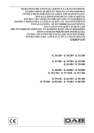
Figure 2.1 below shows a typical servo system
using the RO(L) amplifier. The main source of
noise is usually capacitive coupling. Voltage
transients generated from power semiconductors
couple to the ANALOG CMD lines through
parasitic capacitance CCAP. Reduce CCAP by
using a shielded, twisted-pair conductor for the
ANALOG CMD. Also, separate signal and
motor leads as much as is practical including
routing them in separate conduits or wire ways;
separation also reduces magnetic coupling.
Finally, connect the motor frame to earth ground.
RO(L) INSTALLATION MANUAL
CHAPTER 2 - MOUNTING AND WIRING
6.
Controller
Provide adequate strain relief for all cables
and wires.
RO(L)
Command
Common
CMD+
CMDCommon
CCAP
Motor
MOUNTING
The RO(L) should be mounted in a cabinet or
other suitable enclosure to protect it from
physical and environmental damage. Convection
(non-fan) cooled units must be mounted
vertically. These units require 25 mm (1")
clearance on both sides, as well as at least 25 mm
(1") above and below. See the RO(L) outline
drawing in Appendix B for more information.
Figure 2.1 Capacitive Coupling
Voltage drops across ground leads become more
significant as the distance between the controller
and amplifier increase. Usually, the RO(L)
differential input will correct this problem when
connected as shown in Figure 2.1. Bear in mind
that even though the commons of the controller
and amplifier are electrically connected, there
usually exists a small voltage difference between
the units, especially if they are well separated.
The differential input, with the controller
common connected to ANALOG CMD-,
compensates for this in most cases.
The commons of the controller and amplifier
must be connected as shown in Figure 2.1. The
differential input compensates only for sub-volt
ground noise. The system will not operate
properly if there is a substantial potential across
the commons of the two units.
When wiring your RO(L) system, observe the
following guidelines:
1.
Use shielded, twisted-pair cable for
ANALOG CMD.
2.
Separate motor and signal leads. Run motor
and signal leads in separate conduit or wire
ways.
3.
Minimize lead lengths.
4.
Connect common of controller and
amplifier.
5.
Ground the motor case.
MOUNTING THE FAN
A fan is required to cool the 12 ADC RO(L)
(RO(L)-20012) and 4 ADC units (RO(L)-20004)
that require more regenerative dissipation than
can be obtained with convection cooling. The
fan mounts in the fan bracket, both of which are
standard with the RO(L)-20012. Mount the
fan/bracket assembly 25 mm (1") below or 25
mm (1") above the RO(L) with the air stream
pointed towards the amplifier and flowing
through the heat sink fins. See the fan/bracket
outline drawing in Appendix B for more
information.
WIRING OVERVIEW
The customer is responsible for providing proper
circuit breaker or fuse protection. The customer
is responsible for providing proper wire gauge
and insulation rating for all wiring, including
motor, AC line, and DC bus. The customer is
responsible for making sure that all system
wiring and electrical protection comply with
applicable national and local electric codes.
Strain Relief
All cables that connect to the RO(L) must be
properly strain relieved. Excessive strain causes
damage to the connectors, cables, or PCB and
may result in failure or in unreliable operation.
Ribbon cables must be properly strain relieved.
Absent or inadequate strain relief of insulation
displacement connector (IDC) systems causes
unreliable interconnects.
9
CHAPTER 2 - MOUNTING AND WIRING
Strain relieve all cables
leading to the RO(L).
CAUTION
Strain may cause damage
which will result in failure or
in unreliable operation.
RO(L) INSTALLATION MANUAL
bypass capacitor (>1000 uF) must be placed
within three feet of the servo amplifier.
When multiple RO amplifiers are installed in a
single application, avoid ground loops by
observing the following guidelines:
1.
Run separate power supply leads from
each amplifier to the bus capacitor(s).
2.
Run separate twisted-pair, shielded
cables to ANALOG CMD (+ and -) of
each amplifier.
Motor Protection
Be aware that fusing the power supply input lines
does not necessarily limit current in the
individual motor leads, especially when the
motor is stalled or rotating slowly. The pulsewidth modulation (PWM) topology used in this
amplifier can produce large motor currents from
small line currents. Do not rely on power-supply
fusing to limit current in the motor leads. If
motor leads must be current limited, then protect
the motor leads with motor overload relays or
fuses in addition to fusing the power supply input
lines.
Bus Capacitor (RO Only)
The customer must provide bus capacitance for
RO amplifiers (the ROL provide sufficient
capacitance internally.) PWM amplifiers
generate current surges from the reservoir
capacitors. For single-phase AC input to a diode
bridge, a bus capacitance of 2000 uF/amp
(maximum output current) is recommended; this
value reduces ripple to 4V, which will keep
capacitor temperature low. Lower values of bus
capacitance can be used for three-phase input.
Also, lower values can be used with high-grade
electrolytic capacitors. Contact capacitor
manufacturers for guidelines. Twist leads from
reservoir capacitor.
Regeneration
During braking, the amplifier returns the servo
motor's kinetic energy to the power supply
capacitor. This process raises the capacitor
voltage. If the returned energy is sufficiently
large, an over-voltage fault will be generated and
the amplifier will disable. This problem can be
corrected two ways: for the RO, increase the
value of capacitance and, for the ROL, dissipate
the energy through a shunt resistor.
Increasing Bus Capacitor (RO)
For the RO, over-voltage due to regen can
sometimes be corrected by increasing the bus
capacitance. This works best when the amount
of energy to be returned is small. That is, load
inertias are small and overall change in velocity
is limited. The larger the amount of energy, the
larger the bus capacitors. In some applications,
the capacitors can become so large as to be
impractical. This method works only on the RO
as the connections to the bus are inaccessible on
the ROL.
Dissipation of Regen Energy (ROL)
CAUTION
For RO amplifiers, customer
must provide adequate bus
capacitance. Inadequate
capacitance will degrade
system performance and
generate excessive heat in
bus capacitors.
The bus capacitors should be within three feet of
the amplifier. If they are farther, an additional
10
The ROL provides a "regen" unit, a circuit to
dissipate regenerative energy into a shunt
resistor. That resistor is mounted on the inside of
the ROL cover. For 4 ADC units, which are
convection cooled, the regen resistor can
dissipate 10 watts (continuous). For 12 ADC
units, which are fan cooled, that resistor can
dissipate 30 watts. If you have an application for
a 4 ADC unit and there is a large amount of
regenerative energy, you can order a 12 ADC
unit (which includes a fan kit) and set SW1-3 for
4 ADC operation.
RO(L) INSTALLATION MANUAL
CHAPTER 2 - MOUNTING AND WIRING
Table 2.1
Silverline Encoder
For ROL amplifier:
If load inertia is large or if
rapid deceleration occurs
frequently, regen unit will
overheat. Permanent damage
will occur.
CAUTION
Monitor case temperature
behind regen resistor.** If
case temperature exceeds
60°°C, regen is overloaded.
Stop operation immediately!
Pin
1
2
3
4
5
6
7
8
9
10
Signal Name
Not Used
+5 (Cust. Supplied)
Common
Not Used
Channel AChannel A+
Channel BChannel B+
IndexIndex+
**Regen resistor is located on the cover {}
Motor Cable
For minimal generation of electrical noise, use of
a twisted, shielded conductor for long motor
power cables is recommended. Ground the
shields at both ends: to the amplifier's chassis
ground and to the motor's frame. The motor
power input leads are connected to the amplifier's
output.
WIRING THE ENCODER
The standard SILVERLINE encoder uses a 10pin ribbon cable connector. It is wired according
to the HEDL ® standard from Hewlett-Packard.
Refer to Figure 2.2 (page 17). If you are using a
standard SILVERLINE encoder or any encoder
compatible with the HEDL standard, you may
connect the encoder to a BJ-BKO-10 breakout
terminal strip and from there, wire to the RO(L).
Also, you can wire from the encoder directly to
the RO(L) using discrete wires and appropriate
connectors such as AMP 102387-1 shells.
Always strain relieve the encoder cable. If the
encoder cable is disconnected or cable
connections are broken, the motor will run away.
Strain relieve at the connectors and along the
length of the cable if necessary. Be particularly
thorough when providing strain relief in
environments with significant vibration.
The SILVERLINE line driver module is shipped
loose in the same bag as the loose motor. When
attaching the line driver, proper ESD precautions
should be observed. The line driver attaches so
that the body of the connector fully lies between
the metal hoops on the encoder. It is possible to
install the line driver module incorrectly.
On SILVERLINE motors, strain relief for the
encoder cable is provided with a wire tie which
secures the ribbon cable connector and line
driver to the encoder body. Use a 0.1" wide,
4.5" long wire tie such as Richo WIT-18R. This
wire tie fits securely in notches of the standard
SILVERLINE encoder ribbon-cable connector
(Amp 746285-1). Two steel hoops are attached
to the encoder body through which the wire tie is
threaded. Note that the connector does not have
an integral strain relief, as the version with strain
relief cannot be fastened reliably with a wire tie.
Since the connector does not provide strain relief
for the cable, this function is also provided by the
wire tie. Assemble as shown below: fold the
ribbon cable across the back of the connector to
form a small loop and install the wire tie
securely, preferably with a wire-tie gun or similar
device.
11
CHAPTER 2 - MOUNTING AND WIRING
Wire Tie
Strain
Relief
Loop
Ribbon Cable
Ribbon-Cable
Connector
Line Driver
Hoops
Encoder Body
Side View: Application of wire tie to
secure and strain relieve ribbon cable
RO(L) INSTALLATION MANUAL
For the ROL, when using J1, you will need a
long, narrow blade. Insert the blade carefully
into the opening in the package above J1. Be
careful not to inadvertently unscrew any leads in
J1 and not to disturb wiring internal to the ROL.
Be aware that J1 has two connections hidden by
the frame and you must not loosen those
connections. Doing so will allow internal wiring
for the DC bus to come loose. These wire when
loose present a shock hazard.
If the encoder cable is
disconnected, the motor will
run away!
WARNING
WARNING
Vibration can loosen and
disconnect this cable!
Strain relieve the encoder
cable at both ends and along
its length.
WIRING THE AMPLIFIER
Refer to Figure 2.3 (page 18) for an overview of
all RO(L) connectors.
For the ROL, J1 has two
terminals hidden by the frame.
Do not inadvertently loosen
these screws or internal
wiring may come loose.
This is a shock hazard.
Table 2.2
Connector J1: Power
Pin
1
2
3
4 (RO only)
5 (RO only)
Signal Name
Motor A
Motor B
Motor C
BUS (-) (Common)
BUS (+)
Wiring Bus Leads (RO only)
Install standard three-prong IEC-style connector
cord which provides 115 VAC line cord in
connector JL. Note that integral to the JL
connector is a line fuse. The fuse holder can be
removed with a small screw driver. The fuse is a
5 mm x 20 mm series 16A fuse such as Wickman
19195-16.
RO amplifiers operate from a single polarity,
unregulated DC power supply. This supply does
not need to be galvanically isolated from the line
so that a suitable power supply may be
constructed without a transformer. The customer
must supply all components including diode
bridge, reservoir capacitor, and regenerative
energy shunt if required. (Note that these
components are integral to the ROL.)
If you are using the ROL with a DC bus, connect
the bus leads to hot and neutral of JL. In this
case, the ROL provides regen for DC input.
Connect bus+ to J1-5; connect bus- to J1-4. Bus
must be 135 - 200 volts DC. Note: for ROL
amplifiers, these connections are made internally.
Wiring JL, Line Cord (ROL only)
Wiring J1, Bus Power and Motor
Leads
J1 is a 5-circuit screw-terminal with connections
on 5 mm (0.2") centers. Note that in highvibration environments, it is often preferable to
crimp a ferrule onto each connection of J1.
Refer to Figure 2.4 for wiring (page 19).
12
Do not reverse the power
supply leads.
WARNING
Severe damage will result.
RO(L) INSTALLATION MANUAL
WARNING
Observe proper ESD
protection procedures when
handling encoder and hall
sensor leads.
Wiring Motor Leads for Kollmorgen
BLDC Motors
Connect the three motor leads according to the
color code shown on Figure 2.4. This figure
shows the color code for both Kollmorgen
SILVERLINE and RBE motors. SW1-10 should
be on to select 120° commutation. Note that hall
sensors are connected to connector J6 which is
detailed below.
CHAPTER 2 - MOUNTING AND WIRING
Wiring Motor Leads for Other BLDC
Motors
The graphs below show the commutation
sequence for 120° commutation (SW1-10 on)
and 60° commutation (SW1-10 off), respectively.
Match the commutation of your motor as
specified by the manufacturer to these graphs. If
you do not have this information, refer to the
empirical method on page 34. Note that hall
sensors are connected to connector J6 which is
detailed below.
Be aware that phasing depends also on the
encoder; if phasing of the encoder or the motor is
reversed, the motor may run away.
Table 2.3 Connector J6
Pin
1
2
3
4
5
6
7
8
Name
POT+
COMMON
POTANALOG CMD+
ANALOG CMDTACH IN
TACH MONITOR
IMONITOR
9
10
11
12
13
14
15
ENABLE'
HALL POWER
HALL COMMON
S3
S1
S2
IMONITOR RET
16
FAULT
Description
+10VDC (5 mA) supply for reference potentiometer.
Signal common.
-10VDC (5 mA) supply for reference potentiometer.
Differential analog input.
Not normally used.
1V = 22 kHz encoder frequency.
If SW1-3 is off, 1V = 1.333 ADC,
if SW1-3 is on, 1V = 4 ADC.
Note: IMONITOR is referenced to IMONITOR RET (pin 16),
not control common. There is usually 70 VDC between this
signal and the other control signals on this connector.
Connect to ground to enable.
+30 mA @ 6 VDC ±10%.
Hall sensor #3.
Hall sensor #1.
Hall sensor #2.
Reference common for IMONITOR (Pin 8). This signal is
connected to BUS- through a 10KOhm resistor. There is usually
about 70 VDC between this signal and other control signals on
this connector.
TTL Signal. High if fault (short circuit, over-voltage, over
temperature, illegal hall combination and power-up reset).
When fault is asserted, the red LED on the front panel will
light.
13
CHAPTER 2 - MOUNTING AND WIRING
RO(L) INSTALLATION MANUAL
Hall
Sensors
S1 (J6-13)
S2 (J6-14)
S3 (J6-12)
Step #
+ Phase
- Phase
1
B+
A-
2
C+
A-
3
C+
B-
4
A+
B-
5
A+
C-
120 Degree Commutation
(assumes CW Torque)
6
B+
C-
CW Rotation
Hall
Sensors
S1 (J6-3)
S2 (J6-4)
S3 (J6-5)
Step #
+ Phase
- Phase
1
B+
C-
2
A+
C-
3
A+
B-
4
C+
B-
5
C+
A-
60 Degree Commutation
(assumes CW Torque)
14
6
B+
A-
CW Rotation
RO(L) INSTALLATION MANUAL
WARNING
Motor may run away if motor
or encoder leads are
connected incorrectly.
Wiring J6, Amplifier Status and
Control
J6 is a 16-pin Molex crimp connector with
connections on 2.4 mm (0.1") centers. See
Figure 2.5 (page 20).
CHAPTER 2 - MOUNTING AND WIRING
connector such as AMP 102387-1 on the
encoder.
If you are using a standard Silverline encoder or
any other encoder that supplies differential
signals, connect only the non-inverting signals as
shown in Figure 2.6.
The customer is responsible for providing
5 VDC for the encoder. For Silverline encoders,
this normally requires approximately 100 mA. If
you are using a non-Silverline encoder, be aware
that many encoders use much more than 100 mA
when selecting the encoder power supply.
The mating connector part for J6 is:
Table 2.4 Connector J9
Molex plastic body: 22-01-3167
Insert terminals: 08-50-0114
Crimp tool: 11-26-0009
Pin
1
2
Name
N/C
A
J9 is a 5-pin crimp style connector.
3
4
N/C
B
The mating connector part for J9 is:
5
COMMON
Wiring J9, Encoder
Molex plastic body: 22-01-3057
Insert terminals: 08-50-0114
Crimp tool: 11-26-0009
Refer to Figure 2.6 (page 21). If you are using a
standard SILVERLINE encoder you can use a
BJ-BKO-10, a 10-pin ribbon-cable DIN-rail
mounted breakout from Kollmorgen. The
breakout provides screw-terminal connectors for
wiring to J9. Connect the encoder via ribbon
cable to the BJ-BKO-10, and then connect
discrete wires from the BJ-BKO-10 screw
terminals to J9. You can also use discrete wires
directly from J9 to the encoder by using a
Description
Channel A of
quadrature encoder.
Channel B of
quadrature encoder.
Reference common
for customer
supplied encoder
power.
Switch SW1
SW1 is a 10-position, surface-mount switch
block. These switches control operational modes
such as loop type (velocity or current), test,
gains, scaling, and commutation type. The
settings are detailed below. Chapter 3 discusses
how to set up the amplifier for various modes of
operation.
15
CHAPTER 2 - MOUNTING AND WIRING
RO(L) INSTALLATION MANUAL
Table 2.5 SW1 Settings
Switch
SW1-1
Name
Test/Offset
SW1-2
Current Loop
Gain
Current
Scaling
SW1-3
SW1-4
SW1-5
SW1-6
SW1-7
SW1-8
SW1-9
SW1-10
Vel. Loop
Integrator
Duty Cycle
Encoder Tach
Velocity
Direction
Current
Reduction
Velocity Loop
Gain
120°
Commutation
Description
Normally off. If on, greatly increases sensitivity to offset pot to
allow testing.
Normally on. Off for high inductance (>2 mH) motors.
On for 12 ADC units; Off for 4 ADC units.
Caution: For 4 ADC units, turning SW1-3 on will cause
unreliable amplifier operation and may damage the motor.
On for velocity loop and open loop; off for current loop. When
on, shorts velocity loop integrator.
Normally off. On for open-loop mode.
On for encoder-based velocity loop. Off otherwise.
Normally off. On to reverse direction.
Warning: Reversing SW1-7 may cause the motor to run away.
Normally on. Off to reduce continuous current.
Normally off. On to "detune" velocity loop.
Normally on. Off for brush motors and some brushless DC
motors.
Table 2.6 RO(L) Connector Function
J1 (RO Only)
Name
Bus and
Motor Power
Type
5-Pin Screw
Terminal
Description
Connections for motor power leads and for
bus power
J1 (ROL Only)
Motor Power
Connections for motor power leads only
J6
Status,
Control, and
Hall Sensors
Feedback
Encoder
Line Voltage
with Integral
Fuse
3-Pin Screw
Terminal
15-Pin Crimp
Connector
J9
JL (ROL Only)
16
5-Pin Crimp
Connector
3-Pin Pluggable
ANALOG CMD, ENABLE, AMP OK,
Hall Sensors
Feedback Encoder connection for Velocity
Loop Systems
Three-prong IEC-style connector; 115
VAC line cord
RO(L) INSTALLATION MANUAL
CHAPTER 2 - MOUNTING AND WIRING
N/C
+5 Supply
Common
N/C
Channel AChannel A+
Channel BChannel B+
IndexIndex+
Silverline Encoder
Pin 1
Pin 2
Pin 3
Pin 4
Pin 5
Pin 6
Pin 7
Pin 8
Pin 9
Pin 10
Figure 2.2 Silverline Encoder
17
CHAPTER 2 - MOUNTING AND WIRING
RO(L) INSTALLATION MANUAL
Loop Gain Pot
Current Limit Pot
Scaling Pot
Test/Offset Pot
ON
10
SW1
1
1
J6
Control, Status, and
Hall Sensors
16
1
5
1
JL
AC Power
and Fuse
(ROL only)
JL
5
J9
Encoder
J1
Amplifier Power
and Motor Leads
Figure 2.3 RO(L) Connector Layout--Main PCB
18
RO(L) INSTALLATION MANUAL
CHAPTER 2 - MOUNTING AND WIRING
JL (ROL Only)
AC Line
(ROL only)
In-Connector
Fuse
+
Bus Power and
Logic Power
J1-5 (RO Only)
-
DC BUS
(RO only)
J1-4 (RO Only)
C
Motor B
Leads
A
HALL POWER
HALL COMMON
S3
Hall
Sensor S1
Inputs
S2
RO(L) Amplifier
J1-3
Black
J1-2
White
J1-1
Red
J6-10
Blue
J6-11
Green
J6-12
Yellow
J6-13
Brown
J6-14
Orange
Motor
Power
Hall
Sensors
SILVERLINE/RBE
Motor
Figure 2.4 Connectors J1 and J6 for SILVERLINE/RBE Motors
(J6 Hall Sensors shown; remainder of J6 connections shown in Figure 2.5)
19
CHAPTER 2 - MOUNTING AND WIRING
RO(L) INSTALLATION MANUAL
Amplifier
Status
Input
Amplifier
Status
J6-16
AMP OK
J6-4
ANALOG CMD+
+
Input (+/- 10 Volts
= Full Command)
J6-5
Enable
ANALOG CMD-
J6-9
ENABLE’
J6-2
COMMON
Positioner
POT+ (10V, 5 mA)
Analog
Optional
Input (J6-4)
J6-1
POT- (-10V, 5 mA)
J6-3
IMonitor
Meter
J6-8
J6-15
IMonitor
Return
Note: IMonitor and
IMonitor Return are
referenced to bus-,
not to logic ground.
RO(L) Amplifier
Figure 2.5 Connector J6 Amplifier Enable, Command and Status
(Hall Sensors shown in Figure 2.4)
Do not short IMONITOR (J6-8) or IMONITOR RET (J6-15) to ground!
Do not connect to oscilloscope ground!
CAUTION
20
IMONITOR (J6-8) and IMONITOR RET (J6-15) are not isolated; they are
referenced to bus-. There is normally 70 VDC between these signals and
ground.
RO(L) INSTALLATION MANUAL
CHAPTER 2 - MOUNTING AND WIRING
10-pin ribbon cable
(no connect)
+5 Supply
Common
(no connect)
Pin 1
Pin 1
Pin 2
Pin 2
Pin 3
Pin 3
Pin 4
Pin 4
5 Volt DC Power
Supply
(Cust. Supplied)
J9-5 Common
Channel AChannel A+
Pin 5
Pin 5
Pin 6
Pin 6
Pin 7
Pin 7
Pin 8
Pin 8
Pin 9
Pin 9
Pin 10
Pin 10
J9-2
Chan. A
Channel BChannel B+
J9-4
Chan. B
IndexIndex+
SILVERLINE
Encoder
RO(L)
BJ-BKO-10
Breakout
Feedback Encoder
Figure 2.6 Connector J9
Feedback Encoder (Velocity Loop Mode Only)
21
CHAPTER 2 - MOUNTING AND WIRING
22
RO(L) INSTALLATION MANUAL
CHAPTER 3 - CHECK OUT
RO(L) INSTALLATION MANUAL
CHAPTER 3
CHECK OUT AND COMMISSIONING
________________________________________________________
START UP AND CHECK OUT
You should now be ready to test your system
functions. Be prepared to remove power at any
time. Limit switches and safety devices should
be operational. In multi-axis systems, work with
one axis at a time.
Do not spin the motor without
power!
WARNING
Unexpected operation may
occur. The amplifier may be
damaged.
Do not spin a motor when the amplifier is
disabled. The motor can act as a generator and
charge the power supply. This will cause
unreliable operation and may damage the
amplifier. Also, the ROL may become
operational unexpectedly because it has an
internal power converter that operates from the
high voltage supply.
WARNING
Do not short the motor at a
high speed. This may damage
the motor and the amplifier.
When the motor is shorted, its own generated
voltage may produce very high current flow. The
short and associated arcing may damage the
motor and the amplifier.
Mode Selection
The RO(L) amplifiers can operate in the
following modes:
•
•
•
Open-Loop Mode
Velocity Mode
Current Torque Mode
The RO(L) control section is shown in Figure
3.1. Note that switches SW1-4 and -6 control
mode selection.
23
RO(L) INSTALLATION MANUAL
CHAPTER 3 - CHECK OUT
SW1-9
“Vel. Loop
Gain”
J6-4
ANALOG CMD (+)
50K
0.1uF
“Int. Vel.
Loop”
SW1-4
50K
“Peak/Cont
Current
Limit”
C67*
10K
50K
100K
Scaling
J6-5
50
ANALOG CMD (-)
K
0.01uF
SW1-8
10K
100K
Peak/Cont
Current
Limit
Loop
Gain
SW2-5
+15VDC
10K
500K
Offset/
Test
SW1-2
SW1-1
Current
Limit
10K
-15VDC “Test/Offset”
“Encoder Tach”
“Current Loop
Gain”
10K
R26*
C69*
100K
0.01uF
10K
SW1-6
100K
PWM
SW2-7
Direction
J9-5
Velocity
Sense
J9-2
J9-4
10K
Velocity Monitor (Out)
J6-7
SW1-3 “Current
Scaling”
Current Sense
(Non-isolated)
10K
10K
to
Power
Stage
from
Power
Stage
to Encoder
*R26, C69, C67 can be soldered in by
customer if standard adjustments do not
provide acceptable performance. Always
follow proper ESD protection procedures.
IMonitor Monitor Return
J6-8
J6-15
Note: IMonitor and Monitor Return are
referenced to bus-, not control ground.
Figure 3.1 Control Loop Function Diagram
Open-Loop Mode
Current (Torque) Mode
In open-loop mode, ANALOG CMD directly
controls motor voltage through the PWM section.
This is not a closed loop configuration; the
output voltage varies in proportion to the bus
voltage. In open-loop mode, do not connect the
encoder to the amplifier.
In current-loop mode, ANALOG CMD controls
the current into the motor. For servo motors
such as KOLLMORGEN SILVERLINE Motors,
current is approximately proportional to torque.
Torque mode is used frequently where the
machine controller closes the position and
velocity loops and the amplifier closes the
current loop. In current-loop mode, do not
connect the encoder to the amplifier.
Open loop provides low-performance speed
control for set-up and for less demanding
applications.
24
CHAPTER 3 - CHECK OUT
Velocity Mode
In velocity-loop mode ANALOG CMD controls
motor speed. A speed feedback signal
("tachometer") is synthesized from the encoder
signal and used for loop feedback. Velocity-loop
mode is the most complex mode because a
current loop runs inside the velocity loop; both
loops must be tuned. In velocity-loop mode, the
encoder must be connected to J9. In most cases
the encoder is connected to both the amplifier
and the controller.
Be aware that the performance of the RO(L)
velocity loop is not ideal for all applications.
The RO(L) is designed for low cost and some
features have been omitted. First, the encoder
inputs are "single-ended" rather than differential.
Differential inputs are less susceptible to
electrical noise and are particularly well suited
RO(L) INSTALLATION MANUAL
when the motor and amplifier are in a noisy
environment or separated. Second, the range of
adjustment is limited. Velocity loop operation
may be unacceptable for some applications,
particularly those with large inertial loads and
those requiring high bandwidth. However, the
RO(L) provides locations for various discrete
components which you can solder directly into
the PCB (see C67, C69, and R26 in Figure 3.1).
Start up the Current/Open Loop
Controller
Configure and test current-loop or open-loop
modes. If you plan to use velocity-loop mode,
complete this section with your RO(L) amplifier
in current-loop mode. See Table 3.1 below.
Table 3.1 SW1 Settings: Non-Velocity Control
Switch
SW1-1
SW1-2
SW1-3
Function
Test Mode
Current Loop Gain
Current Scaling
SW1-4
SW1-5
Velocity Loop Integrator
Duty Cycle feedback
SW1-6
SW1-7
SW1-8
Velocity Feedback
Tach Direction
Current (ON = 2:1
Peak/Continuous)
Velocity Loop Gain
120° Commutation
SW1-9
SW1-10
WARNING
Position
OFF
Normally ON
OFF for 4 ADC Units
RO-20004 and ROL-20004
ON for 12 ADC Units
RO-200012 and ROL-200012
ON
Velocity or Current Loop Modes: OFF
Open-Loop Mode: ON
OFF
Normally OFF for Silverline Motors
Normally ON
OFF
Normally ON
THE MOTOR MAY MOVE
UNEXPECTEDLY! STAND
CLEAR OF THE MOTOR!
The amplifier will be enabled
and the motor will turn. Make
sure the motor is secured.
BE PREPARED TO REMOVE
POWER FROM THE RO(L)!
WARNING
This procedure will enable the
RO(L). The system may be
unstable. The motor may
begin oscillating or it may run
away.
25
RO(L) INSTALLATION MANUAL
THE MOTOR WILL RUN AT
FULL SPEED!
WARNING
In current mode, an unloaded
or lightly loaded motor will
run at full speed. Load the
motor or lock the shaft if high
speed rotation is a safety
hazard.
CHAPTER 3 - CHECK OUT
connected improperly. Verify motor wiring
according to Figure 2.4. Also, the commutation
method may be selected incorrectly. Verify that
SW1-10 is properly set: ON for SILVERLINE
and RBE motors and for most other brushless
motors, off for brush motors. If you are using a
non-Kollmorgen motor, refer to the "NonKollmorgen Motor Phasing" section at the end of
this chapter. Often when the hall sensors are
miswired or when the selected commutation
method does not match the commutation of the
motor, the fault LED will flash red and green as
the motor rotates.
Use a non-conductive device
to switch SW1.
CAUTION
A conductive device may slip
and short connections which
may damage the amplifier.
Apply Power and Enable
Apply bus power to your RO(L). Enable the
RO(L) by shorting ENABLE' (J6-9) to
COMMON (J6-2). Check that the LED is green,
indicating normal operation.
Running the Motor
Adjust a separate power supply to about 1 VDC.
Connect the negative side of that power supply to
ANALOG CMD- (J6-5) and to common (J6-2);
connect the positive side to ANALOG CMD+
(J6-4). If the RO(L) is in current mode, an
unloaded motor should rotate at near full speed.
If the RO(L) is in open-loop mode, the motor
will rotate at about 10% of full speed. In either
case, rotation should be smooth.
Slowly reduce the command power supply to
zero and let the motor come to rest. Disable the
amplifier and reverse the power supply and
adjust back to 1 VDC. Enable the amplifier.
The motor should rotate in the opposite direction
at approximately the same speed.
If you do not have a power supply, you can put
the RO(L) in test mode (close switch SW1-1) and
adjust the offset to create a command voltage.
However, using this method disturbs the offset
potentiometer position so that after each use, you
will need to adjust out offset error.
If the motor does not turn or does not turn
smoothly, the hall sensors or motor leads may be
26
Do not short IMONITOR (J6-8)
or IMONITOR RET (J6-15) to
ground!
Do not connect to
oscilloscope ground!
CAUTION
IMONITOR (J6-8) and
IMONITOR RET (J6-15) are not
isolated; they are referenced
to bus-. There is normally 70
VDC between these signals
and ground.
Offset Adjustment
To adjust offset, short ANALOG CMD+ and
ANALOG CMD- to COMMON (J6-4 and J6-5
to J6-2) and adjust trimpot 4 ("OFFSET") until
motor torque is minimized. An unloaded motor
should not turn. Optionally, you can monitor
current with a volt meter across IMONITOR (J68) and IMONITOR RET (J6-15) and adjust until
the meter reads near zero volts.
Command Scaling Adjustment
Command scaling is adjusted at the factory so
that 10 volts generates peak current (or peak
voltage if the RO(L) is in open-loop mode). You
can reduce this scaling by adjusting the GAIN
trimpot.
Peak Current Limit Adjustment
To change current limits, lock the motor shaft.
Turn the Current Limit potentiometer counterclockwise to zero, then turn clockwise to the
appropriate value. For this adjustment, you can
monitor current with a voltmeter from
CHAPTER 3 - CHECK OUT
IMONITOR (J6-8) to IMONITOR RET (J6-15).
The amplifier will produce peak current for about
2 seconds. Lower current commands are allowed
for longer time periods.
You must set the current limit so that the
instantaneous motor current does not exceed the
specified motor peak current rating. This can
permanently damage the motor. For RO(L)
amplifiers, peak current is set at the factory at
two times continuous current. The peak current
of the RO(L)-20004 is normally 8 amps DC; the
peak of the RO(L)-20012 is 25 amps DC. If your
motor peak rating is below these levels you must
adjust down the current limit.
Do not exceed the motor peak
current rating. Adjust down
the current limit to stay within
motor ratings.
RO(L) INSTALLATION MANUAL
dissipate up to 10 Watts (convection) or 30
Watts (fan cooled) of regenerative energy. If you
are using an ROL and you are still experiencing
this fault, your system is probably overloading
the regen unit. Contact your regional office for
more information (see Appendix C).
For ROL amplifier:
If load inertia is large or if
rapid deceleration occurs
frequently, regen unit will
overheat. Permanent damage
will occur.
CAUTION
CAUTION
Improving Current-Loop Performance
For current-loop and velocity-loop systems,
settings from Table 3.1 provide suitable
performance for most systems. The current loop
is stable and should have a bandwidth in excess
of 1000 Hz. If you wish to modify the loop
performance, please refer to discussions on
tuning theory later in this chapter.
LEDs
The RO(L) provides one red/green, light-emitting
diode (LED) on the front. Green indicates that
bus power is applied and that the amplifier is
OK. Red indicates a fault. Faults disable the
amplifier and turn off the amplifier-OK LED.
Removal of the fault condition enables the
amplifier and turns the green LED on.
**Regen resistor is located on the cover {}
If you exceed the RO(L) continuous current
rating for an extended period of time, allow your
unit to cool; it will re-enable automatically. If
this happens regularly, your amplifier may be too
small for the application or your cooling may be
insufficient. Ensure that the ambient temperature
does not exceed the specified maximum (40°C).
For fan cooled units (RO(L)-20012), ensure that
the fan is operational and that air paths are not
blocked. For convection cooled units (RO(L)20004), ensure that the unit is mounted vertically
and that sufficient room is provided on all sides
of the amplifier to allow air to draft up through
the heat sink.
Faults
The RO(L) includes protection against excessive
voltage, current, and temperature. Also, if you
provide an invalid Hall sensor pattern (e.g. all
sensors on in 120° commutation), a fault is
generated. Any fault will turn on the red LED on
the front panel and force AMP OK (J6-16) high.
Monitor case temperature
behind regen resistor.** If
case temperature exceeds
60°°C, regen is overloaded.
Stop operation immediately!
Any fault will inhibit the
amplifier. When the condition
is corrected, the amplifier will
automatically enable.
WARNING
This may cause unexpected
operation and motion!
If you exceed the RO(L) bus voltage (J1-4 and -5
on the RO), the amplifier will fault. The most
common cause of this fault is bus voltage
elevation due to regenerative energy. The ROL
power supply provides a "regen" unit which can
27
RO(L) INSTALLATION MANUAL
CHAPTER 3 - CHECK OUT
Table 3.2 SW1 Settings: Velocity Control
Switch
SW1-1
SW1-2
SW1-3
Function
Test Mode
Current Loop Gain
Current Scaling
SW1-4
SW1-5
Velocity Loop Integrator
Duty Cycle Feedback
SW1-6
SW1-7
SW1-8
Velocity Feedback
Tach Direction
Current Limit (ON = 2:1
Peak/Continuous)
Velocity Loop Gain
120° Commutation
SW1-9
SW1-10
Position
OFF
Normally ON
OFF for 4 ADC Cont.
ON for 12 ADC Cont.
OFF
Current or Velocity Loop: OFF
Open Loop: ON
ON
OFF
Normally ON
OFF
Normally ON
Configure for Velocity Loop
Start up the Velocity Controller
This section describes how to start up the
velocity controller. Before proceeding in this
section, you should complete the "Start up the
Current Controller" section above.
Disable the RO(L).
Check-out the Encoder
Connect a meter or oscilloscope probe to TACH
MONITOR (J6-7). Rotate the motor by hand.
Verify that TACH MONITOR changes as you
rotate the motor. The generated voltages will be
small since TACH MONITOR is scaled for
1.0 volt ≈ 22 kHz of encoder line frequency
(about 1300 RPM for 1000 Line encoder).
Rotate the motor both directions and verify that
the tach changes sign. Do not proceed until your
system passes this test. Running a velocity loop
system with the encoder disconnected or
improperly connected may cause the motor to
"run away"--a condition where the motor
accelerates to full speed without control.
Change your configuration according to
Table 3.2.
Velocity Loop Tuning
Be prepared for the motor to run away when you
enable the system. If the encoder or amplifier are
wired incorrectly, the motor will run full speed.
If this happens, it may be because the system is
phased backwards. If so, inverting SW1-7 will
correct this problem.
If the encoder or amplifier are
wired improperly, the motor
may run away.
WARNING
To reverse direction of
rotation, invert SW1-7.
The velocity loop may be
unstable.
Do not proceed until the
encoder checks out properly.
WARNING
28
Running a system with a
disconnected or improperly
connected encoder may
cause the motor to run away.
Be prepared for the motor to
run full speed.
CAUTION
If the velocity controller is
unstable, reduce the velocity
loop GAIN pot by turning it
counterclockwise (CCW).
CHAPTER 3 - CHECK OUT
RO(L) INSTALLATION MANUAL
Setting Velocity Loop Gain
Adjust the velocity command reference until the
motor speed is approximately 300-400 RPM. If
an adjustable command reference is not
available, the OFFSET pot (Pot 4) can be used as
a command. Turning SW1-1 on will raise the
sensitivity to the OFFSET pot, allowing a much
greater range than normal for offset adjustment.
However, you must adjust offset error out after
each use of the pot for this purpose.
Troubleshooting
Fault
•
•
Verify that the motor shaft rotates freely
with no power applied when uncoupled
from the load.
Verify that the minimum inductance
requirement is met.
To increase the response of the velocity loop,
turn the velocity loop GAIN pot (Pot 1) CW until
the motor is unstable or undesirably "noisy."
Back off approximately one turn, or until the
motor is stable again.
Heat-Sink Temperature
Detuning the Velocity Loop
Over-Voltage Shutdown
Detuning reduces the velocity loop response.
This can be accomplished two ways:
1) reduce GAIN pot, or 2) slowing the velocity
loop integrator. The GAIN pot (Pot 1) can be
manually adjusted by the user (CCW for less
gain), while the velocity loop integrator value is
increased by turning SW1-9 on. (Turning SW19 on detunes the velocity loop.)
Checking the Velocity Loop Response
The response can be monitored on the TACH
MONITOR (J6-7). Attach an oscilloscope and
monitor the motor velocity feedback. Velocity
loop response should be tested by monitoring the
TACH feedback on large velocity transitions.
Quickly switch the velocity command from 0 to
max. Observe the motor velocity feedback for
overshoot and ringing. Adjust the GAIN pot or
change the integrator value by turning on SW1-9.
Verify that the amplifier base-plate temperature
does not exceed 60°C. A thermostat monitors
the plate. Check for air blockage. For fan
cooled units, ensure that the fan is operational.
Check the power input voltage for a value in
excess of those listed in the data sheet. If larger
than listed value is observed, check the AC
power line connected to the power supply for the
proper value.
Under-Voltage Shutdown
Verify power supply voltages for minimum
conditions per specifications.
Short Circuit Fault
Check each motor lead for shorts with respect to
motor housing and power ground.
Measure motor armature resistance between
motor leads with the amplifier disconnected.
Ensure that it is at least 0.2 ohms.
Verify that motor inductance (lead-to-lead) is at
least 250 µH.
Setting Velocity Offset
Short the velocity command (J6-4 and -5).
Enable the RO(L) amplifier. The motor should
not be moving but should have holding torque. If
the motor is rotating slowly, adjust the offset pot
until motion ceases.
Status
•
Check ENABLE' for correct polarity (low
to enable).
•
Check for proper grounding. For
example, ensure that either ANALOG
CMD- (J6-5) or ANALOG CMD+ (J6-4)
is connected to COMMON (J6-2).
•
Mechanical backlash, dead-band,
slippage, etc.
Check Velocity Command Scaling
Attach velocity command reference to J6-4 and
J6-5. Apply the maximum velocity command
which is to be used. Adjust scaling pot until
motor velocity is at the maximum velocity
desired. This sets the ratio between RPM and
velocity command voltage.
29
RO(L) INSTALLATION MANUAL
•
•
Check for excessive noise on encoder
inputs. These inputs should be 0V/5V
square waves. Noise spikes or high
frequencies (> 100 kHz) should not appear
on these lines.
Check for noise on ENABLE'.
STABILITY AND PERFORMANCE
CHAPTER 3 - CHECK OUT
Critical Damping
Generally, the most desirable amount of damping
is Critical Damping. Critically damped systems
respond as fast as possible with little or no
overshoot. The graph in Figure 3.2 shows the
velocity response of a system to a square wave
input when the system is critically damped.
1.20
1.00
Feedback systems such as motor controllers
require tuning to attain high performance. If you
want to tune the current loop or velocity loop,
you will need to determine loop gains according
to a three-part criterion:
•
•
•
Noise Susceptibility
Response
Stability
In a broad sense, the performance of a system is
characterized by its noise susceptibility,
response, and stability. These quantities tend to
be mutually exclusive. The system designer must
decide what noise susceptibility (in the form of a
"busy" motor) is acceptable.
"Busyness" is random activity in the motor and
can often be felt on the motor shaft. Busyness in
a motor should not be confused with PWM noise.
PWM noise is high pitched, relatively constant
noise and is too high in frequency to be felt on
the motor shaft.
Response is a measure of the system's quickness.
Response can also be characterized by bandwidth
and by rise time in response to a step command.
Normally, designers want high bandwidth,
though sometimes the response is purposely
degraded to reduce stress on mechanical
components. This is called detuning. Typical
current loop bandwidths range from 1000 to
2500 Hz. Typical velocity loop bandwidths
range from 20 to 60 Hz.
Stability measures how controlled the system is.
Stability can be measured with damping ratio or
with overshoot in response to a step command.
A discussion of different levels of stability
follows.
30
0.80
0.60
0.40
0.20
0.00
0.000
0.025
0.050
0.075
Time (seconds)
0.100
Figure 3.2 Critical Damping
Underdamping
Sometimes the system is tuned for critical
damping and the system is still too slow. In these
cases, you may be willing to accept less than
critical damping. For applications that can work
properly with a slightly underdamped system,
you may reduce the stability to improve the
response. The graph in Figure 3.3 shows a
slightly underdamped system.
1.40
1.20
1.00
0.80
0.60
0.40
0.20
0.00
0.000
0.025
0.050
0.075
Time (seconds)
0.100
Figure 3.3 Underdamping
CHAPTER 3 - CHECK OUT
RO(L) INSTALLATION MANUAL
ADVANCED CURRENT LOOP
TUNING
Overdamping
An overdamped system is very stable but has a
longer response time than critically damped or
underdamped systems. Also, overdamped
systems are noisier than less damped systems
with the same response rate. The graph in Figure
3.4 shows an overdamped system.
1.00
0.80
Tuning is the process of optimizing several
parameters of operation, including response,
bandwidth, and noise. Tuning is based on
control theory; the goal is to set loop gains with
sufficient gain/phase margin while attaining the
required response.
The Frequency Domain
0.60
0.40
0.20
0.00
0.000
0.025
0.050
0.075
Time (seconds)
0.100
Figure 3.4 Overdamping
Ringing
When you are tuning the RO(L) you may tune it
so that the response rings. Ringing is caused
when you attempt to tune the RO(L) for too rapid
response. Normally, the best solution is to
reduce the bandwidth. The graph in Figure 3.5
shows a system that rings.
1.60
1.40
1.20
1.00
0.80
0.60
0.40
0.20
0.00
0.000
Theory of Operation
0.025
0.050
0.075
Time (seconds)
Figure 3.5 Ringing
0.100
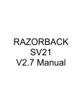
A common way to specify response is measuring
the response of the current loop to a sinusoidal
command over a wide range of frequencies. That
is, measuring the loop response in the frequency
domain. The response of current loops gets
poorer as the command frequency increases,
which is to be expected. When the command is
at very low frequencies, below 10 Hz for
example, the loop is nearly perfect; that is, the
actual current will look very much like the
commanded current. At very high frequencies,
above 10,000 Hz for example, the system will
not be able to respond at all--the command may
represent substantial current, but the actual
current will be very small.
The basic measure of response is referred to as
bandwidth. The bandwidth of a system is
defined as the frequency at which the command
is attenuated to 70% (-3dB) of its low frequency
response. Figure 3.6 shows the response of a
properly compensated current loop with a
bandwidth of 1000 Hz. This graph illustrates a
few key points to understanding response in the
frequency domain. The frequency shown here is
the -3dB point--the point at which the response is
70% of the command. We assume here that the
command and response are scaled the same.
However, in an actual system, you will need to
adjust your scope so the magnitudes show the
same. Do this at a low frequency so you can be
sure the loop is responding without attenuation.
After adjusting your oscilloscope, you can
directly compare the two signals at higher
frequencies. Notice also in Figure 3.6 that the
feedback (current) lags the command. Here, the
lag is about 1/8 of a revolution or 45°. This lag
is typical for a well-behaved system. A large lag
at the -3dB point, especially over 90°, indicates a
somewhat unstable system.
31
RO(L) INSTALLATION MANUAL
CHAPTER 3 - CHECK OUT
Measurement and Control
To observe current loop operation, lock the shaft.
Apply a 10% on-time pulse to ANALOG CMD
(J6-3, -4). Monitor current with a DC current
probe on one of the two motor leads with current,
or measure current with an oscilloscope on
IMONITOR (J6-8) where 1.0 volt is scaled for
either 4A (RO(L)-20012) or 1.33A (RO(L)20004).
Do not short IMONITOR (J6-8)
or IMONITOR RET (J6-15) to
ground!
Do not connect to
oscilloscope ground!
CAUTION
IMONITOR (J6-8) and
IMONITOR RET (J6-15) are not
isolated; they are referenced
to bus-. There is normally 70
VDC between these signals
and ground.
If locking the shaft is impractical, configure the
drive for a zero-torque position: set for 60°
commutation (turn SW1-10 off) and remove the
HALL POWER (J6-10) to disable hall sensors.
This allows current to be commanded without
generating torque. In this procedure, always
apply current in one direction or the shaft will
turn. Use very low current rather than zero
current.
Observe the response to the pulse; it should be
rapid and not overshoot more than 10%. If the
response is not as you desire, change the current
loop gain switch (SW1-2). If response is still
inadequate, turn SW1-2 off and install R26 and
C69, with appropriate values. For tuning, install
them temporarily, one at a time and in increments
of about 20% until you achieve the desired
response.
Figure 3.6 -3dB Point: 70% Attenuation
32
CHAPTER 3 - CHECK OUT
RO(L) INSTALLATION MANUAL
excessive backlash (where there is no load when
gear teeth are not touching).
VELOCITY LOOP PROBLEMS
The mechanical construction can limit the
performance of your velocity loop. The
problems caused by the mechanics fall into three
categories:
1.
2.
3.
Compliance
Non-Linearities
Resonance
Compliance
In compliant systems, the load is not tightly
coupled to the motor shaft. If you move the load
by hand, you can feel springiness. Compliant
systems often are very stable when you tune with
lower target bandwidths. However, they oscillate
vigorously at low frequencies when you try to
tune them for higher bandwidths.
A compliant system has the following
characteristics:
•
There is springiness between the motor
and the load or at the motor mounting
plate.
•
The frequency of oscillation is less than
100 Hz.
Compliance can be corrected by the following
actions:
•
Reduce the bandwidth of the system.
•
Stiffen the machine so the load is not
springy.
Non-Linearities
Tuning is based on linear control theory. The
most important requirement of a linear controller
is that the total reflected inertia should not
change substantially during operation. Load
inertia includes all the inertia reflected to the
motor, such as inertia through gearboxes and
leadscrews. Inertia can change in ways that are
easy to understand, such as the inertia of a spool
of cable decreasing when the cable is unrolled. It
can also change in less intuitive ways, such as
chain drives (which have load in one direction
but are unloaded in the other) and systems with
When the inertia changes, the system has the
following characteristics:
•
System performance is excellent when the
motor is in some positions and
unacceptable when the motor is in other
positions.
•
Reducing the bandwidth eliminates the
problem.
If the system performance is poor because of
changing inertia, you can make the following
corrections:
•
Correct the system mechanics so that
inertia is constant.
•
Detune (that is, reduce the bandwidth of)
the system.
Resonance
Resonance is a high frequency (> 500 Hz) where
the system mechanics oscillate. Normally,
systems with resonance will be very stable when
you tune with lower target bandwidths. As you
increase the target bandwidth, you will begin to
hear a fairly pure, high pitch. If you want to
decrease resonance, use shorter, larger diameter
driving shafts.
When your system has a resonance, it will have
the following characteristic:
•
The system will emit a clear, high pitch
(> 500 Hz). Do not confuse this problem
with compliance, which has a low pitch.
If the system performance is poor because of
resonance, you can make the following
corrections:
•
Reduce the bandwidth of the system.
•
Shorten the length and increase the
diameter of shafts and lead screws.
33
RO(L) INSTALLATION MANUAL
EMPIRICAL METHOD: PHASING
NON-KOLLMORGEN MOTORS
This section discusses how to determine
empirical phasing for non-Kollmorgen motors.
Chapter 2 discussed how to connect nonKollmorgen motors in "Wiring Motor Leads for
Other BLDC Motors." That section is based on
using sequences for either 60° or 120°
commutation. However, if the corresponding
information for the motor is not available, use the
following trial-and-error procedure.
During this procedure, ensure that the motor does
not overheat. Depending on the motor, the
specified analog-command voltage may be too
large. If the motor frame temperature exceeds
50°C, the command should probably be reduced.
If the motor is below 50°C, you should be able to
comfortably rest your hand on it.
If you are operating your RO(L) in velocity loop
mode, temporarily configure for current loop
mode as discussed at the start of Chapter 3.
Phasing by Trial and Error:
1. Turn SW1-10 on if your motor uses
120° commutation. Turn SW1-10 off
for 60°. Contact the motor
manufacturer to determine which is
appropriate.
2. Put the amplifier in open-loop mode
(see Table 3.1).
3. Set ANALOG-CMD for 1.0 volt.
4. Connect the three hall sensor S1, S2,
and S3 leads arbitrarily. (Hall power
and common must be connected
correctly.)
5. Enable the amplifier.
6. Try all six combinations of motor lead
connections until the motor rotates
freely. Always remove power from the
amplifier when changing motor lead
connections.
Note some incorrect wiring combinations will
cause the motor to rotate, but inefficiently and
with zero-torque positions (or "dead spots").
Carefully stop the motor by hand and feel torque
as you let the motor rotate slowly. If the wiring
is correct, torque will be nearly continuous
throughout the rotor rotation.
34
CHAPTER 3 - CHECK OUT
RO(L) INSTALLATION MANUAL
CHAPTER 4 - MAINTENANCE
CHAPTER 4
MAINTENANCE
INTRODUCTION
PREVENTATIVE MAINTENANCE
Information in this chapter will enable you to
maintain the system components, ensuring reliable,
efficient operation of the system. Preventative
maintenance of the equipment is also specified along
with periodic maintenance. Follow these practices
when operating your servo system.
Preventative maintenance can prevent situations that
will damage your equipment. Four types of
preventative maintenance are presented below.
Following each of these procedures can reduce
problems with and add life to your equipment.
SPARE PARTS
BJ-BKO-10: Silverline Encoder Breakout Terminal
The BJ-BKO-10 can be used to simplify Silverline
encoder connections. Mount the breakout near the
amplifier and run a ribbon cable between the breakout
and the motor. Connect J9 to screw terminals as
shown in Figure 2.6. Use scissors to cut ribbon cable.
A bench vise is necessary to make up ribbon cable
connectors.
ROL Slow-Blow Glass Fuse
Wickman 19195-16
16 Amp Fuse
CAUTION
Electronic components in this
amplifier are static sensitive.
Use proper procedures when
handling component boards.
Preventative maintenance should be performed with
the RO(L) system out of operation and disconnected
from all sources of power.
Qty. 1
(The ROL Fuse is located in JL, the line connector.)
35
CHAPTER 4 - MAINTENANCE
Preventative maintenance to
this equipment must be
performed by qualified
personnel familiar with the
construction, operation, and
hazards involved with the
application.
CAUTION
Always take equipment out of
operation and disconnect it
from all power sources before
performing maintenance.
Transient Voltages
NOTE
All transient-producing
devices must be properly
suppressed.
Solid state controls of the RO(L) may be affected by
transient voltages. These voltages may exceed the
specified voltage for any given circuit. When these
peak voltages occur, even for less than a second,
permanent damage can occur.
To help avoid transient voltages that may interfere
with electronic circuit functions within the RO(L), all
switched inductive devices or their wiring (solenoids,
relay coils, starter coils, etc.) must be suppressed. A
220 ohm, 1/2 watt resistor in series with a 0.5 micro
farad, 600 volt capacitor is suggested.
RO(L) INSTALLATION MANUAL
•
Maintain physical separation between electrical
noise sources and the RO(L) control wiring.
This can be accomplished by using separate
conduits or wiring trays for control wiring and
power wiring.
•
Follow good grounding practices when wiring
the RO(L). Be careful not to create a
grounding loop with multiple ground paths.
Follow the NEC's provisions on grounding.
Radio Frequency Energy
This equipment is susceptible to, and can radiate,
radio frequency energy. It must be installed and used
in accordance with this installation manual to limit
possible interference with radio communications or
other electronic equipment.
PERIODIC MAINTENANCE
Periodically you will need to inspect your equipment
for possible problems to ensure ongoing safe and
efficient operation. Periodic maintenance should be
performed at scheduled intervals to ensure proper
equipment performance. It must be performed by
qualified personnel familiar with the construction,
operation, and hazards involved with the RO(L) and
its application. Power should be disconnected during
all maintenance procedures.
Periodic maintenance includes the following:
•
Electrical Noise
The low levels of energy in the RO(L) control circuits
may cause them to be vulnerable to electrical noise.
Sources of electrical noise include equipment having
large, fast changing voltages and currents when they
switch on and off. These devices have the capability
of inducing current and voltage transients on their
respective power lines. Accommodation must be
made for these transients using noise immunity
provisions.
Error! Bookmark not defined.Electrical noise is
prevented with the same methods as surge current and
transient voltages. However, there are other methods
of preventing electrical noise, such as:
•
36
Maintain physical separation between electrical
noise sources and the RO(L) amplifier.
•
•
•
•
Check that no screw terminals have vibrated
loose.
Check fan operation.
Check integrity of wiring.
Check PCBs for accumulation of contaminants
such as fluids, dust, or shavings.
Check all external circuit breakers to assure that
they are within their original ratings as specified
by the manufacturer.
Grounding Integrity
The method employed for grounding or insulating the
equipment from ground should be checked to assure
its integrity on a regular basis. This check should be
performed with the power off and the testing
equipment grounded.
RO(L) INSTALLATION MANUAL
APPENDIX A - WARRANTY INFORMATION
APPENDIX A
WARRANTY INFORMATION
Kollmorgen Corporation warrants that equipment
delivered by it to the Purchaser will be of the kind
and quality described in the sales agreement and/or
catalog and that the equipment will be free of defects
in design, workmanship, and material.
The terms and conditions of this Warranty are
provided with the product at the time of shipping or
in advance upon request.
The items described in this manual are offered for
sale at prices to be established by Kollmorgen and its
authorized dealers.
37
RO(L) INSTALLATION MANUAL
APPENDIX B - OUTLINE DRAWINGS
APPENDIX B
OUTLINE DRAWINGS
This appendix contains outline drawings for H-Series motors and RO(L) electronics.
39
RO(L) INSTALLATION MANUAL
A
PPENDIX
APPENDIX C - REGIONAL SALES OFFICES
C
CUSTOMER SUPPORT
Kollmorgen is committed to quality customer service.
Our goal is to provide the customer with information and
resources as soon as they are needed. This one number
provides order status and delivery information, product
information and literature, and application and field
techncial assistance.
Note: If you are unaware of your local sales representative, please contact us at the number below
. Visit our
web site for MotionLink software upgrades, technical
articles, and the most recent version of our product
manuals.
Kollmorgen Customer Support Network
203 Rock Road Suite A
Radford, VA 24141
Phone: (888) 774-KCSN (5276)
Fax: (540) 639-1640 Inside Sales
Fax: (540) 639-1574 T echnical Suppor t
Email: [email protected]
Http://www.Kollmorgen.com
45
APPENDIX C - REGIONAL SALES OFFICES
46
RO(L) INSTALLATION MANUAL
RO(L) INSTALLATION MANUAL
INDEX
INDEX
BJ-BKO-10, 35
Block Wiring Diagram, 5
Bus Capacitor
Reservoir, 10
Circuit Breakers, 9
Commutation, 26
Commutation Diagram
120 Degree, 14
60 Degree, 15
Compliance, 33
Connector, 36
Connector J1, 12, 19
Connector J6, 15, 19, 20
Connector J9, 15, 21
Connector Layout
Main PCB, 18
Connector Overview, 16
Continuous Current, 3, 27
Convection, 8
Critical Damping, 30
Current
Continuous, 3, 27
Peak, 3
Current Loop Mode, 24
Current Monitor, 26
Detuning, 29, 30
Differential Encoder, 25
Direction
Reversing, 28
Electrical Codes, 9
Electrical Noise, 9, 36
EMI, 9, 36
Encoder, 17
Connection, 11
Phasing, 13
Encoder output
Single ended, 15
Environmental Considerations, 8
Fan, 8
Fault
Hall Sensor, 27
Over-current, 27
Over-voltage, 27
Troubleshooting, 29
Fuses, 9
Grounding Integrity, 36
Hall Sensor Fault, 27
Humidity, 8
IMONITOR, 13, 26, 32
Installation Requirements, 8
Isolation, 12
LEDs, 27
Limitations
Velocity Loop, 25
Maintenance, 35
Mode
Current Loop, 24
Open Loop, 24
Operational, 23
Velocity Loop, 25
Model Number
RO(L), 2
Motor, 13
Encoder Connector, 11
Noisy, 30
Outline Drawings, 39
Protection, 10
Noise Susceptibility, 30
Noisy, 30
Non-Linearities, 33
Open-Loop Mode, 24
Operating Temperature, 4, 8
Operation Mode, 23
Outline Drawings, 39
Over Current, 27
Over-current, 27
Overdamping, 31
Over-Temperature, 27
Over-voltage, 27
Part Number Description, 1
Peak Current, 3
Periodic Maintenance, 36
Phasing Motors, 34
Preventative Maintenance, 35
Pulse Width Modulation, 8
PWM, 8
PWM Noise, 30
Radio Frequency Energy, 36
Ratings, 2
RBE Motor, 13
47
INDEX
Regen, 4, 10, 12, 27
Regional Sales Offices, 45
Resonance, 33
Response, 30
Reversing Direction, 28
Ringing, 31
RO(L)
Model Number, 2
Outline Drawings, 39
Safety information, 7
safety-alert symbols, 7
Single-ended Encoder, 15, 25
Spare Parts, 35
Specifications, 2
Stability, 30
Start up, 23
Static Sensitive, 8
Storage Temperature, 8
Strain Relief, 9, 11
Encoder Connector, 11
System Description, 1
System Wiring Diagram
Velocity Loop Mode, 6
48
RO(L) INSTALLATION MANUAL
Temperature
Operating, 4, 8
Transient Voltages, 36
Tuning, 30
Criterion, 30
velocity loop Problems, 33
Tuning Theory, 31
Underdamping, 30
Unpacking, 8
Velocity Loop, 3
Detuning, 29
Gain Adjust, 29
Offset Adjust, 29
Scale Adjust, 29
Tuning, 28
Velocity Loop Limitations, 25
Velocity Loop Mode, 25
Ventilation, 8
Vibration, 11, 36
Warranty, 37
Wiring, 9
Encoder, 13