Transcript
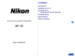
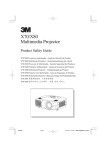
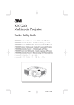
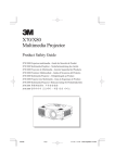
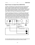
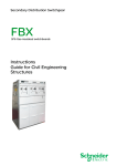
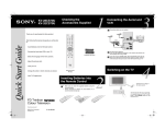
LAMP HES-3030BR CONCEALED HINGE FOR BUILDERS DOORS
INSTALLATION MANUAL
Please follow this manual carefully for proper use.
CAUTION!
・ This concealed hinge is designed for builders doors. We will not be liable for any injuries or damage due to
improper installation, disassembly, modification or use on a door which exceed the specified dimensions
and weights.
・Do not open the door over 180 degrees or open/close with excessive force. It may cause malfunction or
personal injury.
Drawing 1
Dimensions and Weights of
Applicable Doors
Door
Frame
Door
X
G
Doorsill
Slant (indicated by broken lines)
21 3 21
Doors and
Frames Fabrication
A Enlarged View
吊り元各部処理方法
※3≧
R
Door
Door
Bore Fabrication
15 Frame
1. Due to the weight of the hinges the bottom edge of the door mounted with HES-3030BR slants to
the opposite side of the hinges in a certain volume as shown by the broken lines in the Drawing 1.
When installing your door, make a clearance “X” enough to cover such inclination between the door
edge and the doorsill. (Refer to the Drawing 1)
G = “X” + Doorsill Thickness (“X” must be a minimum of 6mm.)
3. Doors and frames must be fabricated properly. They must be warp-free and the four corners
must be square. Improper fabrication may cause scraping of doors and frames against each other
or abnormal noise.
■To make bores in doors and frames for mounting hinges as small as possible:
If you chamfer the corners “A” of doors and frames with R2 or C2, the remaining thickness of doors
can be increased from max. 3 to max. 4 and the remaining thickness of frames from max. 5 to
max. 7. (See the areas indicated by * in the Drawing 2.)
■ Installation Procedure
2
30
30
14
※Max.5
180。
C
2
Frame
2
Side
Door
1. Bore the door and frame as shown in the Drawing 3. The dimensions marked with * in the
Drawing 3 are for standard dimensions. For non-standard dimensions, refer to the Drawing 2.
2. For wooden doors, holes for mounting screws must be made in the specified diameters. For steel
doors, M4x0.7 female screws are recommended as mounting screws. (M4 flat head screws are
recommended.)
3. Mount a leaf of the hinge to the door with supplied mounting screws (Flat head tapping screws).
4. In order to fit the hinge leaves into the bores for a flush surface, tighten the outer hole screws first
and then the inner hole screws.
5. While holding the door, mount another leaf of the hinge to the bore in the frame with supplied
mounting screws (Flat head tapping screws).
191
128
168
4
97
R
Frame
2
Scale/mm
Drawing 3
R
Door
R
A
36 ≦
Frame
Thickness: min. 36mm (1-27/64”)
Weight: max. 50kg (110 lbs.)
2. The above formula is based on the standard application of three HES-3030BR concealed hinges
per door. For standard application of 3 hinges to a door, it is recommended to install the middle
hinge slightly above the midpoint of the door for reinforcement.
C
Drawing 2
Height: max. 2,000mm (78-3/4”)
Width: max. 900mm (35-7/16”)
■Doors and Frames Fabrication
G≦
Floor surface
■Dimensions and Weights of Applicable Doors (for three hinges per door)
6. Tighten all the mounting screws properly to complete installation.
■Caution
10 10
※5≧
30
※3
Drawing 4
+1
0
1 mm
4-make a preparatory hole.φ3.6∼3.8
( Counterbore Depth2 )
Scale/mm
7
21
Drawing 5
1. When mounting hinge leaves to door and frame, the projection from the surface of door/frame
must be limited to 1mm, otherwise it may cause damage to door/frame and restrict the operation
angle of the door. (See the Drawing 4.)
2. After having mounted the hinge, check whether or not the hinge surface is slanted as shown in the
Drawing 4. If the hinge is slanted, loosen the screws and repeat the procedure 4 in the above
Installation Procedure for leveling. When you are unable to correct the slant with this, insert a chip
of wood of appropriate thickness in the hole for mounting screws before fixing the screws.
3. Check whether or not the screw heads are protruding from the surface of hinge leaves. If the screw
heads are protruding, the door may not close completely. (See the Drawing 5.)
Drawing 2: Doors and Frames Fabrication
Correct
Incorrect
Correct
Incorrect
Japan Head Office
U.S.Subsidiary:
1-8-11, Higashikanda, Chiyodaku, Tokyo 101 JAPAN
Phone:813-3866-2260 Fax:813-3866-4447
221 East Selandia Lane, Carson.CA 90746 U.S.A
Phone: 310-329-6373 Fax: 310-329-0819
Toll Free: 1-800-562-LAMP
SUGATSUNE KOGYO CO.LTD
SUGATSUNE AMERICA INC.
www.sugatsune.com