1
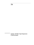
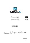
We make compressed air work
Extractor/Dryer®
50 SCFM SERIES
NO. PART NO.
1.
2.
3.
*4.
5.
6.
*7.
8.
*9.
10.
11.
DESCRIPTION
10537
BOLT(4)
10521
WASHER(6)
10501A F23 MANIFOLD 1/4"NPT
10601A F23 MANIFOLD 3/8"NPT
10701A F23 MANIFOLD 1/2"NPT
401
FIRST STAGE CARTRIDGE
402
SECOND STAGE CARTRIDGE
10510
CRP GASKET
10503A F23
CHAMBER
10528
GASKET
10508
BASE CORE
10502A F23
BASE
10535
WEEP DRAIN
SPECIFICATIONS
FILTRATION
5 MICRON
AIRFLOW
50 SCFM
MAXIMUN PRESSURE
250 PSI
DEW POINT
10 TO 35ºF@
ATMOSPHERIC PRESSURE
PORT SIZE
MODEL NT-105 1/4"NPT
MODEL NT-106 3/8"NPT
MODEL NT-107 1/2"NPT
HEIGHT
9.00"
WIDTH
4.00"
DEPTH
2.50"
BOLT TORQUE
50 INCH POUNDS
MAXIMUM TEMPERATURE 180ºF
**SERVICE ITEMS
050SK SERVICK KIT
PATENT NO.RE.32.989-5,261,946
WARNING: Injury can occur if the Extractor Dryer is
used at Pressures higher than the maximum pressure, and with any compressed gases other than normal
compressed air for power tool use only.
We make compressed air work
INSTALLATION INSTRUCTIONSS
WARNING: ALWAYS TURN OFF AIR SUPPLU AND BLEED AIR PRESSURE BEFORE
DISASSEMBLING UNIT OR INJURY COULD RESULT.
WARNING: USE PERSONAL PROTECTIVE EQIPMENT TO PREVEMT EYE INJURY WHEN
SERVICING THIS UNIT.
1. Installation MUST NOT be at the compressor sight install the filter as close as possible to
the machinery or air tools being used.
2. The weep drain (if equipped) should be left open up to 1/4 turn (depending on amount of
liquid in air line) at all times. The weep Drain will allow 10SCFH of air to escape (with
100PSIG line pressure) in the closed position. This will allow water, oil and contamination to
drain from the unit.
3. Replace elements every three to four months (depending on airline conditions).
4. To replace elements, loosen bolts enough to allow cartridges to move freely. Slide out old
filters. Install new filter cartridges. Tighten bolts to specified torque limit in an “X” pattern.
Slowly pressurize unit and check for leaks.
The slider Gauge, under normal operating conditions, will be
in the green area. As the element becomes dirtier over a period
of time, the gauge will slowly move into the red zone
(10 PSIG drop). At this time, changing the filter elements
or cartridges in recommended.
DIFFERENTIAL PRESSURE INDICATORS (OPTIONAL)
1 11032
Screw
2 11026
Switch/Gauge
3 52023
Gasket
4 11031
Screw
5 11024
Gauge
The indicators are factory installed and set to indicate a 10 PSIG pressure drop across the
filter. Under normal operation, the indicating needle will point to the green zone and the
switch contacts will remain open. This indicates a pressure drop of less than 10 PSIG. As the
filter traps dirt, the pointer will move towards the red zone and the switch contacts will move
closer together. When is reached, the pointer will point to the red zone and or the switch
contacts will close actuating a signal that you have installed. At this point, replace the filter
cartridges or elements.
TO POWER
SOURCE
1AMP/50 WATT SPST
MAXIMUM TEMP 200ºF
INDICATOR SWITCH
SIGNAL