1
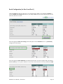
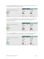
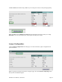
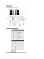
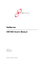
e t B u r n e r
NetBurner
_______________________________________________________
SB72EX User's Manual
Revision: 1.5
February 23, 2006
Status: Released
SB72EX User's Manual, 350030-001
Table of Contents
Overview ............................................................................................................................ 3
Configuration ..................................................................................................................... 3
Hardware Configuration…...………………………………………………………....... 4
Network Configuration…..…………………………………………………...…………5
Operational Configuration .............................................................................................. 5
Network Settings ................................................................................................................ 5
Connection Settings (TCP Mode)..................................................................................... 7
Advanced Serial Data Port Settings .................................................................................. 8
Connection Settings (UDP Mode) ................................................................................... 9
Serial Configuration ........................................................................................................ 10
Jumper Configuration ..................................................................................................... 12
Password Setup ................................................................................................................ 15
Diagnostics ....................................................................................................................... 15
Specifications ................................................................................................................... 15
Power ............................................................................................................................... 16
LEDs ................................................................................................................................ 16
RS-232 NULL Modem Wiring......................................................................................... 16
Network IP Address Configuration................................................................................. 16
Web Browsers and Proxy Servers.................................................................................... 16
Testing with a Telnet Connection.................................................................................... 17
SB72EX User's Manual, 350030-001
Page 2
Overview of the SB72EX Dual-port Serial to Ethernet Device
The NetBurner SB72EX Dual-port Serial to Ethernet device comes preprogrammed and ready to run on
your network. The SB72EX is programmed to convert RS-232, RS-422, RS-485, and TTL data to Ethernet,
enabling communication with your serial device over a network or on the Internet. The onboard web server
provides easy device configuration using a standard web browser.
Front view of the SB72EX, showing the power
input jack, power-on LED, and the Ethernet RJ-45
connector.
Rear view of the SB72EX, showing the two RS-232
(default configuration) serial ports. Port 0 is on the
left; Port 1 is on the right.
Configuration
Before you can begin using your SB72EX, three areas of configuration are required:
1.
Hardware configuration
2.
Network configuration
3.
Operational configuration
You will need to tell your SB72EX what type of serial interface you want to use, the network address you
want your SB72EX to respond to, the serial data baud rate, and the TCP/IP listening port number.
SB72EX User's Manual, 350030-001
Page 3
Hardware Configuration
The SB72EX has two asynchronous UART type serial ports, referred to as Port 0 and Port 1. They are
accessed through two DB-9 connectors. Port 0 can be configured for either RS-232 or RS-485 operation
(the factory default is RS-232), while Port 1 is permanently configured as a RS-232 port.
Note: The default setting (where both Port 0 and Port 1 are RS-232 ports) is appropriate for most
implementations.
If your application requires a single RS-232 connection, then you can use Port 1 (permanently configured
as a RS-232 port), and skip this section because your SB72EX is already configured.
If your application requires two RS-232 connections, the default setting (Port 0 and Port 1are both RS-232)
will work, and you can skip this section because your SB72EX is already configured.
If your application requires a single RS-422/485 connection, then you can configure Port 0 using the
settings below.
To configure Port 0 as RS-422/485, you will need to open up your SB72EX case and change the position of
the five jumpers. (Note: Please take proper ESD precautions. Failure to do so will void your NetBurner
Standard Hardware Warranty.)
There are five 3-pin headers that can be jumpered in one of two positions: connecting pins 1 and 2, or
connecting pins 2 and 3. The five jumpers are located on the SB72EX board as shown below. Remember,
Port 1 is permanently configured as a RS-232 port.
o
To configure Port 0 as RS-485: Position each of the five jumpers so they connect pins 2
and 3.
o
To configure Port 0 as RS-232 (the default configuration): Position each of the five
jumpers so they connect pins 1 and 2.
After you have your SB72EX configured correctly, you must select the corresponding software options
using the web interface.
Network Configuration
The Hardware configuration steps described above must be completed correctly before the software
configuration can take place.
1.
Run IPSetup.exe (by double clicking its icon). This program is located on the CD-ROM that came with
your SB72EX. To view the Advance Settings, click on the Advanced button (the button name will
change to Basic). In this example, I am using Uart 1 as my Monitor port (screen shot below).
2.
Locate your SB72EX in the "Select a Unit" pane by matching its MAC address. The MAC address is
located on the bottom of your SB72EX. If your SB72EX device does not appear in the list box, verify
the power, speed, and link LEDs are illuminated, and click the Search Again button. If you are still
unable to see your SB72EX, remove power, correct any cabling errors, reapply power, and click the
Search Again button. Note: IP Setup uses a UDP broadcast protocol similar to BOOTP and will not
operate through a router.
3.
If your network supports DHCP (factory default): The assigned IP Address will appear in the "Select a
Unit" pane. Write down this address. If your network does not support DHCP, configure the IP
Address and Network Mask fields as shown in the screen shot below. If you need help selecting
values, please read the "Selecting an IP Address" section at the end of this guide. After you have
SB72EX User's Manual, 350030-001
Page 4
entered all of your values, click the Set button in the center of the IP Setup window to configure your
SB72EX with its new parameters. Note: If you do not click the Set button, your values will not be
saved. If you have multiple NetBurner devices, make sure you selected your SB72EX in the "Select a
Unit" pane (as shown in the screen shot) before you input your information.
Operational Configuration
Once the network parameters have been configured, you can use the web server interface to modify the
settings of your SB72EX. To access the web page on your SB72EX, click on the Launch Webpage button
in IP Setup, or you can open your web browser, and enter the numeric IP Address in the address field (e.g.
http://10.1.1.79). Note: For the telnet example on page 19, I have set UART 1 as my Monitor Port.
Network Settings
Below is a screen shot of the top section of the first page that you will see when your web browser opens.
SB72EX User's Manual, 350030-001
Page 5
Parameter
Device Name (for DHCP)
Device IP Address
Device Subnet Mask
Device Gateway
DNS Server
Description
Your NetBurner SB72EX device. Note: The last four values (in the default
name) are the last four digits of the MAC address of your SB72EX.
Displays the IP Address of your SB72EX device. There are two choices:
• If DHCP (from the “Address Mode” drop down menu) is selected,
the SB72EX will obtain its IP Address information automatically,
including the Subnet Mask, Gateway, and DNS Server (if
applicable). This is the factory default.
• If Static is selected (from the “Address Mode” drop down menu, as
shown), you will need to supply the Static IP Address in the edit text
box as shown in the screen shot above.
If you are using a Static IP Address, enter your IP Subnet mask in this text
box as shown in the example above.
If you are using a Static IP Address, enter the IP Address of your Gateway in
this text box as shown in the example above.
If you are using a Static IP Address, enter the IP Address of your DNS Server
in this text box as shown in the example above.
Remember to click the Submit New Settings button on the bottom of this page to save your settings. If
you want the restore your SB72EX to its factory settings (DHCP), click the Reset To Factory Defaults
button.
SB72EX User's Manual, 350030-001
Page 6
Device Connection Settings (TCP mode)
This is the bottom section of the first page that you will see when your web browser opens.
Your choices (for Port 0 and Port 1) for “When to begin making outgoing serial connections:” are:
When you are finished with this section, click the appropriate button at the bottom of the page. Submit
New Settings will save your settings, and Reset to Factory Defaults will restore the factory values. Next,
click on the Advanced Serial Settings link to enter your serial notification information. Remember, if you
are only using one port, you can ignore the other port’s section. Note: For the telnet example on page 19,
the Listening network port number for Port 1 is 24 (the default setting).
To view the Advanced Serial Settings screen click on its link on the bottom of this page.
SB72EX User's Manual, 350030-001
Page 7
Advanced Serial Data Port Settings (for both Port 0 and Port 1)
If you want to have a message displayed in the MTTTY window (or HyperTerminal) when your TCP
connection (e.g. telnet) is established or lost, enter it in this section. Remember to check the appropriate
box and click the Submit New Settings button to save your settings. The message formatting codes are
listed below.
When finished viewing message formatting codes, click the Return to Setup Page button to return to your
Advanced Serial web page. Note: If you are only using one port, you can ignore the other port’s section.
SB72EX User's Manual, 350030-001
Page 8
Device Connection Settings (UDP mode)
Return to the Network section by clicking on the Network link directly above the Advanced Serial section.
Click on the Switch to UDP mode link,(directly under your SB72EX settings) to go to the UDP section.
You will see “System is set to UDP mode” after you click the Switch to UDP mode link
When you are finished with this section, click the appropriate button at the bottom. Submit New Settings
will save your settings, and Reset to Factory Defaults will restore the factory values. Enter your valid
destination IP address as a numeric address separated by periods. Remember, if you are only using one
port, you can ignore the other port’s section.
SB72EX User's Manual, 350030-001
Page 9
Serial Configuration (for Port 0 and Port 1)
Click the Serial link at the top of the page to view the Serial page. When you are finished, remember to
click the Submit New Settings button to save your changes. Note: If you are only using one port, you can
ignore the other port’s section.
Select the appropriate Data Port Setting from the drop down menu. Remember, Port 1 is permanently
configured as a RS-232 port.
Select the appropriate Data Baud Rate from the drop down menu. Your host computer and your attached
SB72EX must agree on a speed or baud rate to use for the serial connection. The factory default is 115200.
SB72EX User's Manual, 350030-001
Page 10
Select the appropriate Data Bits value from the drop down menu. The data bits are the number of bits in a
transmitted data package (the recommended setting is 8).
Select the appropriate Data Parity value from the drop down menu. This feature checks whether data has
been lost or written over when transmitted between your host computer and your SB72EX (the
recommended setting is None).
Select the appropriate Stop Bits value from the drop down menu. The stop bit follows the data and parity
bits in serial communication. It indicates the end of transmission (the recommended setting is 1).
SB72EX User's Manual, 350030-001
Page 11
For Flow Control, the default setting is None. If you are using flow control, set this option appropriately.
Note: You must click the Submit New Settings button on the bottom of this page to save your settings
Remember, if you are only using one port, you can ignore the other port’s section.
Jumper Configuration
Click the Jumper Configuration link on this page to view Port 0 and Port 1 jumper configuration and
pinout information.
Note: To get back to the Serial section after viewing this page, click on the Return to Setup Page button
directly above the SB72EX diagram.
SB72EX User's Manual, 350030-001
Page 12
SB72EX Pinout Information
Click the Return to Setup Page button to return to the Serial section.
SB72EX User's Manual, 350030-001
Page 13
Password Setup Section
Click on the Password link to password protect your web server: Type in your user name, your password,
confirm your password, and click the Submit New Settings button to save your user name and password.
Diagnostics Section
Click the Diagnostics link to view the available options. To get back to the Networking section, click the
Back to Ethernet & Serial Configuration link.
SB72EX User's Manual, 350030-001
Page 14
Specifications
Input Power Requirements
Input Range: 7 – 30VDC
Suggested Power Source: 12VDC @ 500mA
Operating Range: Commercial 0 – 70C
Power Connector
The power input is a standard 2.1mm P5 type input jack. The center is positive, and the
outer shell in negative.
Pin
Center
Shell
LEDs
•
•
•
Signal
7 – 30VDC
GND
Power LED: Illuminated while power is applied.
LED1 on RJ-45: Ethernet speed - 10 or 100
LED2 on RJ-45: Link and data activity
Mechanical
Dimensions: 4.1” x 3.125” x 1.0”
SB72EX User's Manual, 350030-001
Page 15
RS-232 NULL Modem Wiring
The following table and diagram shows how to create a null modem cable/adapter for RS-232 connections.
IMPORTANT: A null modem cable is required if you are connecting your SB72EX to a single computer.
A standard serial cable will not work!
Network IP Address Configuration
If you are part of an existing network, are not using DHCP, stop reading now, and go get a Static IP
Address and Network Mask address from your network administrator. If you follow the advice in this
paragraph on an existing network without an assigned Static IP Address, your Network Administrator will
hunt you down....
IP Addresses are used to route packets from place to place on an Intranet/Internet. If you are not part of an
established network, and your Ethernet segment is isolated, you can choose just about any IP Address you
desire. The "powers that be" have actually set aside some addresses for isolated networks. They are
documented in RFC1918. The reserved ranges are:
Class A: 10.0.0.0 to 10.255.255.255
Class B: 172.16.0.0 to 172.31.255.255
Class C: 192.168.0.0 to 192.168.255.255
If you are doing development on an isolated network, you can use the following addresses:
•
Set your host computer's Network Adapter Card IP Address to 10.1.1.10
Note: Only change the Network Adapter Card; do not change your Dial-Up Adapter settings.
•
Set the Static IP Address of your SB72EX to 10.1.1.11
•
Set the Network Mask address for both your host computer network and your SB72EX to
255.255.255.0
Web Browsers and Proxy Servers
If you are working on a corporate LAN that uses a proxy server for Internet web browsing, you will need to
exclude the IP Address of your SB72EX in your web browser’s proxy server settings/preferences.
Otherwise, an attempt to connect to a web page on the LAN will fail because the proxy server will attempt
to route the request outside the LAN. For most web browsers, this can be accomplished in the advanced
settings for the proxy server configuration. Set the Network Mask for your host computer’s network
adapter and your SB72EX to 255.255.255.0.
SB72EX User's Manual, 350030-001
Page 16
Testing with a Telnet Connection
One quick way to test the functionality of your Serial-to-Ethernet connection is with the Telnet program
and an RS-232 Serial terminal program (e.g. MTTTY). Remember you must use a NULL modem able to
connect your SB72EX to your host computer. To run this test, configure your system as one of the two
examples shown below:
The objective of this example is to use a single host computer running telnet and a serial terminal program
to send data in either direction. Therefore, if you type text in the telnet window, it should appear in the
serial terminal window and visa versa. For a serial terminal, you can use MTTTY (which is included in
your NetBurner SB72EX CD-ROM) or HyperTerminal.
In the following example, an IP Address of 10.1.1.79 will be used for the SB72EX. Note: Replace this
number with the specific IP Address you assigned (if using a Static IP Address) during configuration.
Procedure
1.
Connect your hardware in one of the above configurations.
2.
Open a command prompt window on your host computer.
3.
Verify everything is connected correctly by executing the command ping 10.1.1.79 and pressing
the Enter key on your keyboard. You will see a valid ping response. Remember to substitute
your IP Address for our example IP Address (i.e.10.1.1.79).
4.
Run either HyperTerminal or MTTTY. Set the baud rate to the value you assigned to the SB72EX
during configuration. To use MTTTY (with the factory default settings):
•
Connect your NULL modem cable from Port 0 on your SB72EX to your host
computer’s serial port. Remember, a standard serial cable will not work.
•
Run Mttty.exe (by double clicking its icon), which is located on the CD-ROM that came
with your SB72EX. When the MTTTY window appears use the factory default setting
shown below:
o
o
o
o
o
The Port setting is the communication port that you connected the NULL
modem cable to on your host computer.
The host computer and the attached SB72EX must agree on a speed or baud rate
to use for the serial connection.
Parity checks whether the data has been lost or written over when transmitted
between your host computer and your SB72EX.
Data Bits are the number of bits in a transmitted data package.
The Stop bit follows the data and parity bits in serial communication. It
indicates the end of transmission.
•
Click the MTTTY Connect button.
•
Remove and reapply power to your SB72 EX.
.
SB72EX User's Manual, 350030-001
Page 17
•
The SB72EX factory application will boot.
5.
Run Telnet by typing: telnet 10.1.1.79 24 after the prompt, and press the Enter key. Note: This
assumes a port number of 24. You must replace this port number with the listening port number
that you assigned in the “Device Connection Settings (TCP mode)” section. Remember to
substitute your IP Address for our example IP Address (i.e.10.1.1.79).
6.
At this point, anything you type in the Telnet window should appear in the serial terminal window
and vice versa.
SB72EX User's Manual, 350030-001
Page 18