1
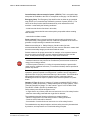
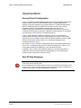
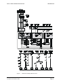
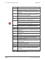
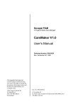
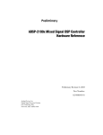
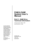
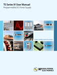
PAM & SAM
System User’s
Manual
Part 3: Safety and
Protective Functions
Ordering Number: 9032 011 983
Issue October 6, 2000
This version replaces all
previous versions of this
document. It also replaces
the SAM System Designer’s
Guide (1995-1996).
Inmotion Technologies and
ACC Motion have made
every effort to insure this
document is complete and
accurate at the time of
printing. In accordance with
our policy of continuing
product improvement, all
data in this document is
subject to change or
correction without prior
notice.
ACC Motion SA
Zone industrielle La Rippe
CH-1303 Penthaz
Switzerland
P/n 9032 011 983
Issue October 6, 2000
© 1995 - 2000
by ACC Motion SA
All rights reserved
PART 3 - SAFETY AND PROTECTIVE FUNCTIONS
PAM with SAM System Users Handbook
P/n 9032 011 983, October 6, 2000
TABLE OF CONTENTS
Page: 2
PART 3 - SAFETY AND PROTECTIVE FUNCTIONS
TABLE OF CONTENTS
Table of Contents
Table of Contents....................................................................................................3
Index of Figures ......................................................................................................3
Index of Tables .......................................................................................................3
Introduction .............................................................................................................5
Overview..............................................................................................................5
Definitions ............................................................................................................5
Implementation .......................................................................................................7
General Circuit Configuration ..............................................................................7
Fast DC Bus Discharge .......................................................................................7
System Power-up ..............................................................................................10
STOP 0 Initiated by a SAM Drive ......................................................................12
STOP 1 Initiated by SAM Drive .........................................................................13
External Emergency Stop with STOP 1 Controlled Stop ..................................14
Safe Power Removal.........................................................................................15
Prevention of Unexpected Start-up ...................................................................15
Index of Figures
Figure 1
Figure 2
Figure 3
Figure 4
Figure 5
Figure 6
Protective and safety interlocks Circuit ....................................................8
Start-up Sequence for a PAM with SAM System...................................11
Sequence for STOP 0 initiated by a SAM Drive ....................................12
Stop 1 Sequence initiated by a SAM Drive ............................................13
Stop Sequence for an External Emergency Stop with Stop 1 controlled
stop.........................................................................................................14
Sequence for Safe Standstill on Axis 2..................................................15
Index of Tables
Table 1
Page: 3
Component Descriptions for Figure 1 ......................................................9
PAM with SAM System Users Handbook
P/n 9032 011 983, October 6, 2000
PART 3 - SAFETY AND PROTECTIVE FUNCTIONS
PAM with SAM System Users Handbook
P/n 9032 011 983, October 6, 2000
INTRODUCTION
Page: 4
PART 3 - SAFETY AND PROTECTIVE FUNCTIONS
INTRODUCTION
Introduction
Overview
This section describes how the built-in safety and protective functions of the PAM
with SAM System may be integrated into machine level controls. The below-listed
terms and definitions from IEC/EN 60204-1, ISO IEC 13849-1 (EN 954-1), and IEC
61800-5 (2nd expert committee draft 22G/64/CD) are used in the discussion of
safety and protective functions and examples of their implementation are presented
in this section.
i
Additional information on the safety and protective functions of the PAM, SAM Drive
and SAM Supply is available in the "PAM Technical Information" "SAM Drive Technical
Information" and "SAM Supply Technical Information" sections of this Users Handbook
respectively.
i
The third-party test report "SAM Power Drive System Safety Related Functions for
prevention of unexpected start-up and for power removal" regarding safety category 3 is
available upon request for machine safety assessment.
Definitions
Power Drive System (PDS): It consists of a Drive (converter section, control
equipment for speed, torque and current, power semiconductors, etc.), a motor
(with built-in sensors), and extensions such as feeding section, field supply, and
auxiliaries. It does not include the driven equipment.
Requirements for Safety Related Functions: The functional safety
requirements of a Power Drive System (PDS) are dependent on the application,
and must be considered as a part of the overall risk assessment of the machine.
The technical measures required for safety related functions depend on a
combination of the consequences of faults within the PDS and the risk of injury at
the machine.
The Drive manufacturer may define certain control functions to be suitable for
safety-critical use; however, the Drive manufacturer does not have a total "view"
of the application. Consequently, the machine designer, who does have a total
"view" of the application, must be responsible for the risk assessment and for
specifying the safety-related requirements for the PDS.
Uncontrolled stop and removal of power (STOP 0): This is a stop achieved by
removal of power from the PDS. It corresponds to category 0 of IEC 60204-1.
Controlled stop followed by removal of power (STOP 1): This is a controlled
deceleration and stop. Power is available to the PDS for the deceleration, and
then removed when the stop has been achieved. It corresponds to category 1 of
IEC 60204-1.
The maximum time that elapses between STOP 1 initiation and removal of power
can be adjusted within SAM Drives up to a maximum duration of one second.
Page: 5
PAM with SAM System Users Handbook
P/n 9032 011 983, October 6, 2000
PART 3 - SAFETY AND PROTECTIVE FUNCTIONS
INTRODUCTION
Controlled stop without removal of power (STOP 2): This is a controlled stop
with power left available to the PDS. It corresponds to category 2 of IEC 60204-1.
Emergency Stop: The Emergency Stop shall function as either an uncontrolled
stop (STOP 0) or a controlled stop followed by removal of power (STOP 1). The
choice of the stop function shall be determined by a risk assessment of the
machine. It must satisfy the following conditions:
- it shall override all other functions in all modes;
- power to the motors shall be removed as quickly as possible without creating
other hazards;
- reset shall not initiate a restart.
Power removal: Power removal requires the power supply to the motor to be
interrupted safely. During power removal, it shall not be possible for the motor to
generate a torque resulting in hazardous movements.
Measures according to i.e. Safety Category 3 shall be taken for both
electromechanical and electronic means of power removal. Electronic means shall
have the same safety integrity as electromechanical means.
Suitable measures for power removal are for example, a line contactor between
the power supply and the PDS, a motor contactor between the Drive and the
motor, or safe pulse blocking of the Drive output semi-conductors.
STOP
- Electronic means are not adequate for protection against electric shock.
- Additional measures may need to be considered to prevent stored mechanical
energy from creating a hazard.
- If external power influences (i.e. falling of suspended loads) are present after
power removal, additional measures (i.e. mechanical brakes) shall be provided to
prevent any hazard.
Prevention of unexpected start-up (Safe Standstill): In some types of
operations, persons exposed to moving parts of a machine can be subjected to
significant risks of injury by inadvertent start-up of the machine. The PDS shall be
safeguarded by technical measures against a faulty, unexpected start-up.
Restarting the PDS must require a positive action such as operation of a pushbutton.
Category 3 (Type 3): the term “category 3” relates to standard ISO IEC 13849-1
(EN 954-1) "Safety of Machinery - Safety-related parts of control systems", Part 1:
"General Principles for Design". It is also named " type 3" in IEC 61800-5 draft.
The ISO IEC 13849-1 (EN 954-1) standard says:
Safety-related parts shall be designed so that:
- a single fault in any of these parts does not lead to the loss of the safety function
- whenever reasonably practicable the single fault is detected
The standard makes the following references to system behavior:
- When the single fault occurs the safety function is always performed.
- Some but not all faults will be detected
- Accumulation of certain faults can lead to the loss of the safety function.
The standard also says that principles to achieve safety are mainly characterised
by structure, and requires the use of well-tried safety principles.
PAM with SAM System Users Handbook
P/n 9032 011 983, October 6, 2000
Page: 6
PART 3 - SAFETY AND PROTECTIVE FUNCTIONS
IMPLEMENTATION
Implementation
General Circuit Configuration
Figure 1 illustrates a general system/machine level circuit configuration designed to
satisfy the requirement of IEC/EN Standard 60204-1 regarding starting and
stopping of electrical equipment in industrial machinery. A PAM with SAM system
with one SAM Supply and two SAM Drives is shown; however, the concepts
illustrated in Figure 1 are applicable to systems with more axes. This
implementation which utilizes the built-in SAM safety and protective functions, in
combination with external components, satisfies the requirements for a “safe power
removal process” and prevention of unexpected start-up.
Figure 1 shows standard components (switches, relays, etc.) for the sake of
explaining the functionality. Achieving safety category 3 at machine level usually
requires the use of redundant, safety certified relays and switches in place of single
standard components. Refer to Table 1 for a functional description of the
components shown in Figure 1.
The system in Figure 1 has been implemented with an electromechanical brake on
axis 2. Axis 1 is equipped with short-circuit dynamic braking (via K9 and RB). K9 is
de-energized whenever the SAM Drive is not controlling the motor.
In addition, axis 2 is shown with additional features (K7 and others) providing a
“safe power removal” and preventing unexpected start-up. A PLC performing
overall machine control also inputs to the circuit.
Fast DC Bus Discharge
STOP
Page: 7
If no Fast DC-bus Discharge means is used, hazardous and lethal voltages remain for
60 seconds after removing power.
Should additional DC-bus Capacitors be used, then a Fast DC-bus Discharge circuit
must be used in order to keep the discharge time within 60 seconds. It shall also be
used if for any reason a shorter discharge time is required.
PAM with SAM System Users Handbook
P/n 9032 011 983, October 6, 2000
PART 3 - SAFETY AND PROTECTIVE FUNCTIONS
IMPLEMENTATION
SAG001_c.cdr
Figure 1
PAM with SAM System Users Handbook
P/n 9032 011 983, October 6, 2000
Protective and safety interlocks Circuit
Page: 8
PART 3 - SAFETY AND PROTECTIVE FUNCTIONS
Symbol
Description
FE (3)
FATAL ERROR output
- one per each SAM Drive and SAM Supply.
Contacts are closed whenever no fatal error condition exists.
K1
AC starting relay - switches AC power to the power drive system
during startup. K1 is de-energized once the DC Bus capacitance
has charged.
K2
AC Run relay - is energized once the DC Bus capacitance has
charged and before K1 is de-energized
K3
System Stop relay - de-energizing K3 forces an immediate STOP
0. The contacts in series with K3’s coil form the system stop chain.
K4
Emergency Stop relay - de-energizing K4 forces an immediate
STOP 1, followed after 2 seconds by a STOP 0.
K5
Time delay relay - has a 2 second delay upon de-energization
The 2 second delay is given here as an example. Machine safety
considerations may require other delay times
STOP
K6 (optional)
Bus Fast Discharge relay - when energized provides a path
through resistance RDBR for discharging the DC Bus capacitance
K7 (optional)
Safe stop relay for axis 1. Relay de-energized for safe stop
K9 (optional)
Emergency Brake relay for axis 1. Relay operated by the brake
control option.
PLC1
PLC function 1 - controls application of AC power to SAM Supply
via inrush resistors
PLC2
PLC function 2 - controls application of AC power directly to the
SAM supply
PLC3
PLC function in stop chain
PLC4
PLC function 4 - controls selection of fast bus discharge
Q1
AC Supply circuit breaker
RB (optional)
Short circuit resistors - control deceleration duration during
dynamic braking. With ACC motors, a short circuit may be used
instead of resistors.
RDBR
External dynamic braking resistor
RIRL
In-rush current limiting resistors
S1 (ESTOP)
Emergency Stop push button
S2 (Reset)
Reset switch - used to clear the ESTOP condition and enable
return to normal operation. An additional command required to
restart motion.
S3
safe stop switch for axis 2. A key switch is normally used.
Table 1
Page: 9
IMPLEMENTATION
Component Descriptions for Figure 1
PAM with SAM System Users Handbook
P/n 9032 011 983, October 6, 2000
PART 3 - SAFETY AND PROTECTIVE FUNCTIONS
IMPLEMENTATION
System Power-up
The basic circuit configuration of Figure 1 provides the interlocks necessary to
insure that the PAM with SAM system cannot be set into motion unless the PAM,
SAM Drives and SAM Supply have passed all power-up diagnostic checks and are
ready for normal operation. Any fault/error condition producing a STOP 0 or STOP
1 condition within a SAM Drive or any fatal error condition within a SAM Supply
inhibits closure of the FATAL ERROR contact on the defective unit, thereby preventing
closure of K3, K2 and K1.
Figure 2 illustrates a typical start-up sequence executed by a host PC/PLC using
the circuit of Figure 1 along with the SAM Drive and SAM Supply status outputs.
PAM with SAM System Users Handbook
P/n 9032 011 983, October 6, 2000
Page: 10
PART 3 - SAFETY AND PROTECTIVE FUNCTIONS
IMPLEMENTATION
Apply 24
VDC Power
20 sec. delay
Establish
communication
NO
Communication
OK?
YES
NO
DC BUS LOW = 1
OVERTEMP = 0
DBR OVERLOAD = 0
OVERVOLTAGE = 0
SAM Supply
Status OK?
YES
NO
SAM Drive
Status OK?
YES
>10s since
last Start-Up?
Abort
Start-Up
NO
YES
Close PLC1
WAIT 0.3 s
NO
Open PLC1
DC BUS LOW
= 0?
YES
Close PLC2
Abort
Start-Up
Open PLC1
Start-Up
completed
sag006_b.dsf
Figure 2
Page: 11
Start-up Sequence for a PAM with SAM System
PAM with SAM System Users Handbook
P/n 9032 011 983, October 6, 2000
PART 3 - SAFETY AND PROTECTIVE FUNCTIONS
IMPLEMENTATION
STOP 0 Initiated by a SAM Drive
A SAM Drive executes a STOP 0 when it detects a serious error condition (i.e.
short-circuit in motor cable) requiring immediate removal of output power to the
motor and AC power to the drive system. Figure 3 shows the sequence of events in
the drive system illustrated in Figure 1 when axis 2 executes a STOP 0. Note that
Axis 2 (aided by the brake on the axis motor) executes an immediate uncontrolled
stop. Energy stored in DC Bus circuit helps stop axis 1 in a controlled way (STOP
1) after the AC Supply is disconnected.
Axis 2 initiates a
Stop 0 due to
internal error
condition
Axis 2 Power Stage
disabled
Axis 2 fatal error relay
opens
K3 deenergized
Brake Control turns off
brake current Axis 2
Axis 2 mechanical
brake actuates
Axis 2 Stop0 executed
status bit set
Some delay
Host controller detects
status change on axis2
K1 & K2 deenergized
K4 deenergized
AC Supply
disconnected
K5 deenergized
Stop 1
to Axis1 & Axis2
2 seconds delay
Axis1 controlled stop
1 second delay
Stop 0
to Axis1 & Axis2
Max. 1 second delay
Host closes contact
PLC4
Axis1 power stage
disabled
Host opens contacts
PLC1 & PLC2 and stop
the whole machine
K6 energized
Discharge DC Bus
sag002_b.dsf
Figure 3
PAM with SAM System Users Handbook
P/n 9032 011 983, October 6, 2000
Sequence for STOP 0 initiated by a SAM Drive
Page: 12
PART 3 - SAFETY AND PROTECTIVE FUNCTIONS
IMPLEMENTATION
STOP 1 Initiated by SAM Drive
A SAM Drive executes a STOP 1 when it detects an error condition (i.e. motor
overload) necessitating a controlled stop of the drive system. Figure 4 shows the
sequence of events in the drive system of Figure 1 when axis 1 executes a STOP
1. In this example, the host controller, upon sensing the STOP 1 condition on axis
1, issues a STOP 1 command to axis 2.
Axis 1 initiates a
Stop 1 due to
internal error
condition
Axis 1
executes controlled
stop
Axis 1
"Stop1 executed"
status bit set
Small delay
Some delay
Axis 1
Power stage
disabled
Axis 1
brake control turns
off brake curent
Host controller
detects status
change on
Axis 1
Axis 1 "Fatal error"
relay opens
K9 deenergized
Host controller
orders Stop1 to the
whole machine
K3 denergized
Some delay
K4 deenergized
Host controller
opens contacts
PLC1 & PLC2
K5 deenergized
Stop1
to Axis 1 & Axis 2
Some delay
2 seconds delay
Axis 2 controlled
stop
Host closes contact
PLC4
Stop 0
to Axis 1 & Axis 2
Max, 1 sec. delay
K6 energized
Axis 2 power stage
disabled
Discharge DC Bus
K1 & K2
deenergized
AC Supply
disconnected from
SAM System
R B short-circuit
Axis 1 motor
sag003_b.dsf
Figure 4
Page: 13
Stop 1 Sequence initiated by a SAM Drive
PAM with SAM System Users Handbook
P/n 9032 011 983, October 6, 2000
PART 3 - SAFETY AND PROTECTIVE FUNCTIONS
IMPLEMENTATION
External Emergency Stop with STOP 1 Controlled Stop
Figure 5 illustrates the sequence when an external Emergency Stop (ESTOP)
button on the machine is actuated.
ESTOP Switch
actuated
(switch opens)
K4 deenergized
K5 deenergized
Host controller detects
K4 open
Axes executes Stop1
commands
2 seconds delay
Host controller stops
the whole machine
Max. 1 sec. delay
Stop0 to all axes
K1 & K2 deenergized
Stop1 to all axes
All axes power stages
disabled (Safety cat. 3)
AC Supply
disconnected from
SAM System
Some delay
Host controller closes
contact PLC4
K6 energized
Discharge DC bus
sag004_b.dsf
Figure 5
PAM with SAM System Users Handbook
P/n 9032 011 983, October 6, 2000
Stop Sequence for an External Emergency Stop with Stop 1 controlled stop
Page: 14
PART 3 - SAFETY AND PROTECTIVE FUNCTIONS
IMPLEMENTATION
Safe Power Removal
Once one second has elapsed upon Emergency Stop activation, the system
configuration of Figure 1 and the sequences of Figure 5 satisfy the requirements for
safe power removal, according to safety category 3.
Prevention of Unexpected Start-up
The system configuration of Figure 1 satisfies the requirements for prevention of
unexpected start-up. Starting from the condition of the machine not running (at an
Emergency stop condition), axis 2 motor may be isolated by setting S3 to the open
position. Figure 6 illustrates the sequence. Any single fault within SAM drive 2 while
axis 2 is isolated produces a STOP 0 error and result in opening of its "Fatal Error"
relay which, in turn, stops the entire drive system and disconnects it from the AC
Supply. S3 is normally a key operated switch. To ensure that others cannot remove
the safe standstill condition, the operator normally removes the key from the switch.
Machine is at an
operational stop
condition
(PLC5 opened)
S3 opens
K7 deenergized
Axis 2 Brake Control
turns off brake current
Stop1 to Axis 2
Axis 2 mechanical
brake actuates
Max. 1 sec. delay
Stop0 to Axis 2
Axis 2 power stage
disabled (Safety cat. 3)
sag005_b.dsf
Figure 6
Page: 15
Sequence for Safe Standstill on Axis 2
PAM with SAM System Users Handbook
P/n 9032 011 983, October 6, 2000