1
MR-8XX Series IC Card Reader/Writer
MR-780
MR-780
MR-780
MR-810/800/790
用户手册
V1.0
用户手册
V1.0
用户手册
V1.0
User's Manual
03/01/2012
No.
Version
Remarks
1
V1.0
01/04/2010 The initial version
Copyright © 2003-2011 Jinmuyu Electronics Co., LTD. All rights reserved.
0
MR-8XX Series IC Card Reader/Writer
Contents
1. Overview ...........................................................................................................................3
1.1 PICC .................................................................................................................................................... 3
1.2. Technical parameters .......................................................................................................................... 4
2. Interface description ..........................................................................................................5
2.1 Hardware Interface .............................................................................................................................. 5
2.2 ATR ................................................................................................................................................... 6
3.APDU Operation .............................................................................................................7
3.1 Smart card ............................................................................................................................................. 8
3.2 SAM ................................................................................................................................................... 8
3.3 Contactless memory card ...................................................................................................................... 8
3.4 Non-standard APDU (PC/SC Part3 Definition section) ........................................................................ 8
3.4.1 GetData........................................................................................................................................... 9
3.4.2 LoadKey ....................................................................................................................................... 10
3.4.3 Authentication .............................................................................................................................. 12
3.4.4 ReadBinaryBlock ......................................................................................................................... 14
3.4.5 UpdataBinaryBlock ...................................................................................................................... 15
3.4.6 ValueBlockOperation ................................................................................................................... 18
3.4.7 ReadValueBlock........................................................................................................................... 19
3.4.8 RestoreValueBlock....................................................................................................................... 21
3.5 Non-standard APDU (Custom section) ............................................................................................... 22
3.5.1 Set ISO14443A Detecting card mode ......................................................................................... 24
3.5.2 Halt TypeA Cards ........................................................................................................................ 25
3.5.3 MifarePlus Shift Level0 to Level1/3 ........................................................................................... 25
3.5.4 Set ISO14443 TypeB Detecting card mode ................................................................................ 26
3.5.5 Halt TypeB .................................................................................................................................. 26
3.5.6 AT88F020 Count ......................................................................................................................... 27
3.5.7 AT88F020 Deselect ..................................................................................................................... 27
3.5.8 AT88F020Lock ........................................................................................................................... 27
3.5.9 ISO15693 Inventory .................................................................................................................... 27
3.5.10 ISO15693 Stay Quiet.................................................................................................................. 28
3.5.11 ISO15693 Select Tag.................................................................................................................. 29
3.5.12 ISO15693 Reset to Ready .......................................................................................................... 30
3.5.13 ISO15693 WriteBlock ................................................................................................................ 30
3.5.14 ISO15693 Read Block ................................................................................................................ 31
3.5.15 ISO15693 Write AFI .................................................................................................................. 31
3.5.16 ISO15693 Lock AFI ................................................................................................................... 32
3.5.17 ISO15693 Write DSFID ............................................................................................................. 32
3.5.18 ISO15693 Lock DSFID .............................................................................................................. 33
3.5.19 ISO15693 Get System info......................................................................................................... 33
3.5.20 ISO15693 Get M Blk Sec St ...................................................................................................... 34
3.5.21 ISO15693 Lock Block ................................................................................................................ 34
3.5.22 Set SAM Baud Rate (Set PPS) ................................................................................................... 35
Copyright © 2003-2011 Jinmuyu Electronics Co., LTD. All rights reserved.
1
MR-8XX Series IC Card Reader/Writer
3.5.23 Set SAM baud rate after reset (through PPSS) ........................................................................... 36
3.5.24 Switch current operating smart card ........................................................................................... 36
3.5.25 Initialize RTC time (Only MR-800/810 support) ....................................................................... 38
3.5.26 Read RTC time (Only MR-800/810 support) ............................................................................. 38
3.5.27 Set RTC Time display (Only MR-800 support) ......................................................................... 39
3.5.28 Set RTC Date display (Only MR-800 support) .......................................................................... 40
3.5.29 Set LCD Chinese font type display (Only MR-800 support) ..................................................... 40
3.5.30 Read LCD Chinese font type display (Only MR-800 support) .................................................. 41
3.5.31 LCD Display the specified number of Chinese or English fonts (Only MR-800 support) ......... 41
3.5.32 LCD Display picture (Send picture data directly) (Only MR-800 support) ............................... 42
3.5.33 LCD Erase the line (Only MR-800 support) .............................................................................. 43
3.5.34 LCD Set the boot screen (Only MR-800 support) ...................................................................... 43
3.5.35 LCD Set the standby screen (Only MR-800 support) ................................................................ 44
3.5.36 LCD Backlight control (Only MR-800 support) ........................................................................ 45
3.5.37 LCD Showing Flash storage picture (Only MR-800 support).................................................... 46
3.5.38 Read card outside Flash .............................................................................................................. 47
3.5.39 Write card outside Flash ............................................................................................................. 47
3.5.40 Obtain product serial number ..................................................................................................... 48
3.5.41 Get the hardware version and the version number ..................................................................... 48
3.5.42 LED light control........................................................................................................................ 48
3.5.43 Buzzer control ............................................................................................................................ 49
3.5.44 Set Antenna Status...................................................................................................................... 50
3.5.45 Set Card encryption method ....................................................................................................... 50
3.5.46 Restore the factory default (System restart) ............................................................................... 50
3.5.47 System restart ............................................................................................................................. 51
4. Card operating procedures .......................................................................................... ….51
4.1 Contact and Contactless Smart Cards.................................................................................................. 52
4.2 Memory Cards ..................................................................................................................................... 53
5. Contact Us .................................................................................................................. ….60
Appendix A ......................................................................................................................... 61
Copyright © 2003-2011 Jinmuyu Electronics Co., LTD. All rights reserved.
2
MR-8XX Series IC Card Reader/Writer
1. Overview
MR800 series desktop contactless IC card reader/writer (containing MR-790/800/810) is
based on NXP series RF chip with high performance ARM7 MCU (But MR-790 is 51 MCU).
The communication is according to USB PC/SC standard. The reader fully support the IC
crad according to ISO14443 and ISO15693 standards, especially completely support
ISO14443-4 contactless CPU card. User can choose freely if with the LCD display module
(128x64) or not (MR-800 with LCD, MR-810/790 without LCD). The readers can be directly
used the Windows operating system with driver and the API functions. The development
cycle is simple and short. The reader builds in 2 SAM slots, and fully supports SAM
according to ISO7816.
In order to the developer's convenient application, we can offer VC、BC、VB、DELPHI
programs(SDK). The developer can come into work quickly via using our offering SDK.
1.1 Cards
supported (PICC)
● Mifare One S50
● Mifare One S70
● Mifare Ultra Light
● Mifare Plus
● ST SR176
● ST SRIX4K 、SRI512
● AT88RF020
● ISO14443-4 TYPE A & B
● TI RFid Tag-it HF
● NXP I.Code SLI (I.Code 2)
● Other ISO15693 Tags
● SAM (T=0 /1)
Copyright © 2003-2011 Jinmuyu Electronics Co., LTD. All rights reserved.
3
MR-8XX Series IC Card Reader/Writer
1.2. Technical
parameters
Qualifications:
• PCD: NXP RC531, RC632; RC400, RC500 (select)
• Flash memory: AT45DB321
• Working frequency: 13.56MHz
• RF standard: ISO14443A, ISO14443B, ISO15693
• Operating distance: 100mm (Mifare One, typical distance)
• SAM card slot: 2 slots, (supports ISO7816 T=0 and T=1)
• Interface: USB PC/SC
• Power supply: USB DC5V
• Power consumption: 0.9W
• LED: four LED (red, green, blue, yellow)
• Dimension: 123mm × 88mm × 25mm
• Weight: About 200g
• Operating temperature: -25 ~ +85 ℃ (-77 ~ +185°F)
• Storage temperature: -40 ~ +125 ℃ (-104 ~ +257°F)
• PC software: PTransWin
• SDK&Program: VC, VB, C++ Builder, DELPHI, Power Builder
• Manual
Note:
1、Using which kinds of chips according to the users want to read the card types.
2、For the reading distance, there are some different, because of the different card types or
coming from different producers.
3、As to the SAM cards support T=0/1 protocol, so the reader can automatically choose the
communicate protocol according to the reset information. Uesers don't need set.
4、MR-800/810 has 2 SAM slots, and MR-790 has 3 SAM slots.
5、MR-790 and MR-810 doesn't support green LED light.
6、Only MR-800 support LCD display and RTC.
Copyright © 2003-2011 Jinmuyu Electronics Co., LTD. All rights reserved.
4
MR-8XX Series IC Card Reader/Writer
2. Interface description
2.1 Hardware Interface
MR800's interface is USB PC/SC; the interface description is as following:
Pin
Signal
Function
1
2
3
4
Vbus
D+
DGND
+5V power input
Data line+
Data line-
GND
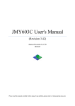
After power on, to check the rfid reader connection: My PC-> Characteristic
->Hardware-> Device Manager
The correct connection is just like the above picture: USB Smart Card reader。
Copyright © 2003-2011 Jinmuyu Electronics Co., LTD. All rights reserved.
5
MR-8XX Series IC Card Reader/Writer
2.2 Answer to reset (ATR)
According to PC/SC Part3 protocol, when the reader power on and get the return ATR
information from the SmartCard, in order to let the reader read more contactless smart cards,
MR-800 using the return to a fixed reset information (not including the card information).
Information format is as following:
Byte
Value(Hex)
Designation
0
3B
Initial Header
Description
Higher nibble 8 means: no TA1, TB1, and TC1 only TD1 is
1
8N
T0
following.
Lower nibble N is the number of historical bytes (HistByte
0 to HistByte N-1)
Higher nibble 8 means: no TA2, TB2, and TC2 only TD2 is
2
80
TD1
following.
Lower nibble 0 means T = 0
3
4
To
3+N
01
TD2
80
T1
Lower nibble 1 means T = 1
Category indicator byte, 80 means A status indicator may
be present in an optional COMPACT-TLV data object
4F
Application identifier Presence Indicator
0C
Length
RID
Tk
SS
Registered Application Provider Identifier
(RID) # A0 00 00 03 06
Byte for standard
C0 .. C1
4+N
Higher nibble 0 means no TA3, TB3, TC3, TD3 following.
Bytes for card name
00 00 00 00
RFU
RFU # 00 00 00 00
UU
TCK
Exclusive-oring of all the bytes T0 to Tk
The MR-800 Series reader, we return to the fixed ATR as follows:
ATR = {3B 8F 80 01 80 4F 0C A0 00 00 03 06 00 00 00 00 00 00 00 68}
Copyright © 2003-2011 Jinmuyu Electronics Co., LTD. All rights reserved.
6
MR-8XX Series IC Card Reader/Writer
3 . Application Protocol Data Unit (APDU)
Operation
There are two kinds of APDU for MR800 series reader: Standard APDU (the Class of
APDU is not 0xFF) and Non-Standard APDU (the Class of APDU is 0xFF).
For contactless
SmartCard and contact SAM cards, in order to let it be compatible with PC / SC standard, we
not only can get the cards reset information, but also can directly send the rest standard APDU
to the SmartCard or SAM cards. As the MR-800 support contactless SmartCard and contact
SAM cards, so you can choose which one you want to operate via switching the current
operating cards' APDU(APDU:FF 00 FA 00 01 CurSmartCard). The detailed card operating
procedures, please reference the later chapters. Memory card, we have adopted a Class = FF
non-standard APDU command extended operation, the instruction described in later chapters.
Whether the non-contact SmartCard, contact SAM card or memory card, all the operation of
the card the first step must be the GetData APDU to obtain card information, and only to
obtain card information you can go on the follow-up operation.
3.1 Contactless Smart Card
Contactless Smart Card is following the standard APDU command. Before
sending the standard APDU command, we need through GetData command to
obtain SmartCard ATR data. During the operation, If you need read the SAM
card, you need switch it to the specified SAM Slot (APDU: FF 00 FA 00 01
CurSmartCard) to read the relevant data.
Copyright © 2003-2011 Jinmuyu Electronics Co., LTD. All rights reserved.
7
MR-8XX Series IC Card Reader/Writer
3.2 SAM Card
MR-800 series reader/writer have serval SAM card slots (MR-800/810 two
SAM card slots, MR-790 three SAM card slots). Before sending the standard
APDU command, we need through GetData command to obtain SAM card reset
information. During the operation, if you need read the contactless smart card or
SAM card, you need switch instruction to shift it to the contactless smart card or
SAM card. For example: During the operation, when the reader read the
contactless card, this need be certificated by SAM data.
3.3 Contactless Memory Card
MR-800 support Mifare one/Ultralight and so on. In order to let it be
compatible with PC / SC standard, we have defined Non-standard APDU.
Before sending Non-standard APDU command, we need through GetData
command to detect the card and also obtain Card serial number information.
3.4 Non-standard APDU (PC/SC Part3 defined parts)
GetData APDU can operate memory card and SmartCard/SAM. The other
Non-standard APDU is mainly used to the operation of the storage class card.
The standard APDU is mainly used to the operation of the SmartCard/SAM
card.
The wrong feedback (SW1/SW2) status is as following:
Copyright © 2003-2011 Jinmuyu Electronics Co., LTD. All rights reserved.
8
MR-8XX Series IC Card Reader/Writer
Result
SW1
SW2
Wrong note
success
90
00
Operation success
failure
63
00
Operation failure
failure
6A
81
Non-support
failure
6B
00
P1-P2 Parameter error
3.4.1 GetData
The APDU command is in order to obtain Card serial number or reset information.
Before operating a card, the APDU must be run at first, because of which contains the switch
of the type of card which the reader will read.
Send APDU format:
Command
Class
INS
P1
P2
Le
GetData
FF
CA
CardType
SubCardType
00
CardType and SubCardType are defining as following:
ISO
ISO14443
CardType
SubCardType
00:ISO14443 A Mifare card
00
01:ISO14443 A Smartcard(ISO14443-4)
00
02:MIFARE Ultra Light
00
03:Mifare Plus
00: Mifare PLUS Level0
Type A
01: Mifare PLUS Level1
02: Mifare PLUS Level2
03: Mifare PLUS Level3
04: Mifare PLUS Level1for switch level
ISO14443
Type B
ISO15693
ISO7816
20:ISO14443 B Smartcard(ISO14443-4)
00
21:SR176
00
22:SRIX4K/SRI512
00
23:AT88RF020
00
40:ISO15693 Tag(Only one Tag)
00(NXP/TI Tag)
60:ISO7816-Contact(T=0/T=1)
00:SAM1
01:SAM2
02:SAM3
03:SAM4
Copyright © 2003-2011 Jinmuyu Electronics Co., LTD. All rights reserved.
9
MR-8XX Series IC Card Reader/Writer
MIFARE 1K/4K/UlraLight/MifarePlus Level1 (P1 = 00/02/03)
Answer:
Response
Result
Data Out
UID Len(1Byte) + UID (LSB- 4/7Byte) + ATQA(2byte) + SAK(1Byte)
SW1
SW2
MIFARE Plus Level0/2/3/1 for switch and ISO14443 - 4 TypeA SmartCard (P1 = 01/03)
Answer:
Response
Data Out
UID Len(1Byte) + UID (LSB- 4/7Byte) + ATQA(2byte) + SAK(1Byte)+
Result
SW1
SW2
SW1
SW2
SW1
SW2
ATQA(nByte)
ISO14443 - 4 TypeB SmartCard/AT88F020 (P1=20/23)
Answer:
Response
Result
Data Out
ATQB(12Byte)
SR176/SRIX4K (SRI512) (P1=21/22)
Answer:
Response
Result
Data Out
CHIPID(1Byte)+UID(8Byte)
ISO15693 Tag (P1=40)
Answer:
Response
Result
Data Out
DSFID(1Byte)+UID(8Byte)
SW1
SW2
SW1
SW2
ISO7816 SAM (P1=60)
Answer:
Response
Result
Data Out
Reset Info(nByte)
Copyright © 2003-2011 Jinmuyu Electronics Co., LTD. All rights reserved.
10
MR-8XX Series IC Card Reader/Writer
Such as:
1、 TypeA request cards:
Send:
FF CA 00 00 00
Receive:04 72 AE A6 9E 04 00 08 90 00
2、 ISO14443 TypeA Smartcard:
Send:
FF CA 01 00 00
Receive:04 50 3D CE EB 08 03 20 11 28 A1 53 43 41 5F 4F 5F 56 31 30 30 5F 54 64 90 00
3、 ISO14443 TypeB SmartCard:
Send: FF CA 20 00 00
Receive: 50 C0 1281 89 54 46 22 08 00 80 A1 90 00
3.4.2 LoadKey
The APDU is used to save the card authorized keys and readers key. The LoadKey can be
chosen to save or not save. The key that is not saved temporarily stored in RAM, easily lose
after power off,but hardly lose after power off if it was saved in Flash. The Max. Card keys
which can be saved in MR-800 are 32 pcs. Each key is Max.16 bytes. If the authorized key is
less than 16 bytes, then take the low-byte key. The Max. Reader keys which can be saved in
MR-800 are 1 pcs.
Send APDU format:
Command
Class
INS
P1
P2
Lc
Data
LoadKey
FF
82
KeyStructure
KeyIndex
1~16
KeyData(LSB)
Copyright © 2003-2011 Jinmuyu Electronics Co., LTD. All rights reserved.
11
MR-8XX Series IC Card Reader/Writer
KeyStructure:
b7
b6
b5
b4
b3
b2
b1
b0
Description
0:card key
X
1:reader key
0:plaintext
transmission
X
1:Ciphertext
transmission
0:Temporary
storage
X
1:racetrack
storage
X
X
X
X
X
RFU
The card is authorized via the card key. Reader key is the encryption key, when the key is to
be loaded the card. The way of encryption is 3DES, so the reader key must be 16 bytes. The
key for the encrypted card must be a multiple of 8 bytes. If it not enough, to fill 00 in the high
byte. Such as Mifare one: the key is FF FF FF FF FF FF six bytes key, if loading the key to
choose ciphertext transmission,firstly need to add 0 to FF FF FF FF FF FF 00 00 (LSB..MSB)
then to encrypt; If to choose plaintext transmission, no need add 0. The entire default key is 0.
The key storage structure/pattern:
Key Index
Card key(Byte)
Reader key(Byte)
0
16
16
1
16
-
……
16
-
31
16
-
(Card key index 0~31, reader key index only 0)
Answer:
Response
Result
Data Out
SW1
SW2
Copyright © 2003-2011 Jinmuyu Electronics Co., LTD. All rights reserved.
12
MR-8XX Series IC Card Reader/Writer
For example:
1、 If to use plaintext transmission—ReaderKey, no need save:
Send:
FF 82 80 00 10 33 11 22 33 44 55 66 77 88 99 AA BB CC DD EE FF
Receive:90 00
3.4.3 Authentication
The APDU is mainly used to authorize the card with a key protection. After the GetData
command, if the card with a key protection, Firstly the card need be authorized by the APDU,
and then to do the following read and write operations.The cards need to be authorized:
Mifare S50/70、MifarePlus、AT88F020. There are two kinds of authentication to choose, one
is via the already stored in the key or download key.
Send APDU format:
Command
Class
INS
P1
P2
P3
Data
Authenticate
FF
88
HighAddress
LowAddress
KeyType
KeyCofig+KEY
P1/P2:
Mifare S50/70, MifarePlus Level1 (being Compatible with MifareClassic), it to be the
cards' block address.
AT88F020, The address is invalid. (P1=0, P2=0)
For MifarePlus Level2/3/1(Switch-level), it to be the AES key storage blocks address.
(Note:Key storage block and data block is the corresponding relationship. Please refer to
MifarePlus data manual.)
KeyType:(Only in Mifare S50/S70,MifarePlus Level1(being Compatible with MifareClassic),
the byte is valid: A Key-0x60, B Key-0x61)
Copyright © 2003-2011 Jinmuyu Electronics Co., LTD. All rights reserved.
13
MR-8XX Series IC Card Reader/Writer
KeyConfig:
b7
b6-b0
Meaning
0
XXXXXXX
XXXXXXX it means using the input KEY length,Card using the current key
authorization.
1
XXXXXXX
XXXXXXX That means the stored key index in the reader, the card uses the stored key
authorization.
KEY:
KeyConfig Bit7 = 0,it Indicates that the key, the key length is different depending on
the type of card.
KeyConfig Bit7 = 1,the Key does not exist.
Answer:
Response
Result
Data Out
SW1
SW2
For example:
1、Mifare S50 request card, the first data block read:
Send:
FF CA 00 00 00
Receive:04 72 AE A6 9E 04 00 08 90 00
Send:
FF 88 00 01 60 06 FF FF FF FF FF FF
Receive:90 00
Send:
FF B0 00 01 10
Receive:00 11 22 33 44 55 66 77 88 99 AA BB CC DD EE FF 90 00
2、MifarePlus Level3 request card, to read the data block 0:
Send:
FF CA 03 03 00
Receive:07 04 8B AD 04 05 06 07 42 00 31 0C 75 77 84 02 4D 46 50 5F 45 4E 47 90 00
Send:
FF 88 40 00 00 10 FF FF FF FF FF FF FF FF FF FF FF FF FF FF FF FF (data block 1—the
key address is 0x4000 or 0x4001)
Receive:90 00
Send:
FF B0 00 01 10
Copyright © 2003-2011 Jinmuyu Electronics Co., LTD. All rights reserved.
14
MR-8XX Series IC Card Reader/Writer
Receive:11 11 11 11 11 11 11 11 11 11 11 11 11 11 11 11 90 00
3、AT88F020 request card, to read the data block 9:
Send:
FF CA 23 00 00
Receive:50 00 04 E8 51 00 00 00 00 00 00 41 90 00
Send:
FF 88 00 00 00 08 00 00 00 00 00 00 00 00
Receive:90 00
Send:
FF B0 00 09 08
Receive:00 00 00 00 00 00 00 00 90 00
4、 The reader key is transfered via plaintext transmission:00 01 02 03 04 05 06 07 08 09 0A 0B 0C 0D
0E 0F
Ciphertext transmission Mifare, sector 1 key:FF FF FF FF FF FF 00 00
3DES after encryption:E5 FC BD 49 E6 4A F7 E4
To use the stored key to read sector 1:
Send:
FF 82 80 00 10 00 01 02 03 04 05 06 07 08 09 0A 0B 0C 0D 0E 0F (The reader key is
transfered via plaintext transmission)
Receive: 90 00
Send:
FF 82 60 00 08 E5 FC BD 49 E6 4A F7 E4 (The card key is transfered via encryption
transmission to Index = 0)
Receive:90 00
Send:
FF CA 00 00 00 (Request)
Receive:04 72 AE A6 9E 04 00 08 90 00
Send:
FF 88 00 00 60 80 (To be authorized via use the stored key)
Receive: 90 00
Send:
FF B0 00 00 40 (To read sector)
Receive:72 AE A6 9E E4 88 04 00 46 10 EF 05 32 36 30 31 00 01 02 03 04 05 06 07 08 09 0A 0B 0C
0D 0E 0F 00 00 00 00 00 00 00 00 00 00 00 00 00 00 00 00 00 00 00 00 00 00 FF 07 80 69
FF FF FF FF FF FF 90 00
Copyright © 2003-2011 Jinmuyu Electronics Co., LTD. All rights reserved.
15
MR-8XX Series IC Card Reader/Writer
3.4.4 ReadBinaryBlock
The APDU read the card stored block data mainly according to the requested card type
which is specified by GetData APDU. If the card with key protection, before reading the card
blocks data, it need be authorized (APDU: Authentication).
Send APDU format:
Command
Class
INS
P1
P2
Le
ReadBinary
FF
B0
HighAddress
LowAddress
DataLen
P1/P2:The block address
DataLen:The data length (ALL data are LSB first)
• MIFARE 1K/4K
16 bytes
• MifarePlus
16 bytes (Level3 Support for multi-block read)
• MIFARE Ultralight 4 bytes
• SR176
2 bytes
• SR512
2 bytes
• SRIX4K
2 bytes
• AT88RF020
8 bytes
• ISO15693 Tag
4 bytes (Support for multi-block read)
The APDU support for multi-block read command(Note:the card also need support for
multi-block read command). if to read ISO15693 Tag two in a row,DataLen = 4x2 = 8. Note:
the operation that the APDU to read is to the last tag which was detected. If to operate the tag
which was chosen or specified UID, please refer to 3.5 sections: Non-standard APDU
(Custom section).
Answer:
Response
Result
Data Out
Data
SW1
SW2
Copyright © 2003-2011 Jinmuyu Electronics Co., LTD. All rights reserved.
16
MR-8XX Series IC Card Reader/Writer
For example:
1、 SR176 request card, to read the block 10:
Send:
FF CA 21 00 00
Receive:20 42 2F 69 18 08 92 D0 02 90 00
Send:
FF B0 00 0A 02
Receive:00 00 90 00
2、 MIFARE Ultralight request card, to read the block 10:
Send:
FF CA 02 00 00
Receive:07 04 24 A2 E1 BF 02 80 44 00 00 90 00
Send:
FF B0 00 0A 10
Receive:11 22 33 44 00 00 00 00 00 00 00 00 00 00 00 00 90 00
3、 ISO15693 Tag to read the block 10 and 11:
Send:
FF CA 40 00 00
Receive:00 3D 3D 08 17 00 01 04 E0 90 00
Send:
FF B0 00 0A 08
Receive:00 00 00 00 00 00 00 00 90 00
3.4.5 UpdataBinaryBlock
The write the block operation is according to the requested card type which is specified by
GetData APDU. If the card with key protection, before writing the card blocks data, it need be
authorized (APDU: Authentication).
Send APDU format:
Command
Class
INS
P1
P2
Lc
Data
UpdataBinary
FF
D6
HighAddress
LowAddress
DataLen
Data
P1/P2:The write block address
DataLen:The write data length (ALL data are LSB first)
•MIFARE 1K/4K
•MifarePlus
•MIFARE Ultralight
•SR176
16 bytes
16 bytes (Level3 Support for multi-block read)
4 bytes
2 bytes
Copyright © 2003-2011 Jinmuyu Electronics Co., LTD. All rights reserved.
17
MR-8XX Series IC Card Reader/Writer
•SR512
•SRIX4K
•AT88RF020
•ISO15693 Tag
4 bytes
2 bytes
8 bytes
4 bytes
The APDU support for multi-block write command(Note:the card also need support for
multi-block write command). if to write ISO15693 Tag two in a row,DataLen = 4x2 = 8. Note:
the operation that the APDU to write is to the last tag which was detected. If to operate the tag
which was chosen or specified UID, please refer to 3.5 sections: Non-standard APDU
(Custom section).
Answer:
Response
Result
Data Out
SW1
SW2
For example:
1、Mifare S50----------request card, the first data block read /write:
Send:
FF CA 00 00 00
Receive:04 72 AE A6 9E 04 00 08 90 00
Send:
FF 88 00 01 60 06 FF FF FF FF FF FF
Receive:90 00
Send:
FF D6 00 01 10 01 02 03 04 05 06 07 08 09 0A 0B 0C 0D 0E 0F 00
Receive:90 00
Send:
FF B0 00 01 10
Receive:01 10 01 02 03 04 05 06 07 08 09 0A 0B 0C 0D 0E 0F 00
2、 MifarePlus Level1-----------the fourth data block read /write:
Send:
FF CA 03 01 00
Receive:04 72 AE A6 9E 04 00 08 90 00
Send:
FF 88 00 04 60 06 FF FF FF FF FF FF
Receive:90 00
Send:
FF D6 00 04 10 00 00 00 04 05 06 07 08 09 0A 0B 0C 0D 0E 01 00
Receive:90 00
Copyright © 2003-2011 Jinmuyu Electronics Co., LTD. All rights reserved.
18
MR-8XX Series IC Card Reader/Writer
Send:
FF B0 00 04 10
Receive:FF D6 00 04 10 00 00 00 04 05 06 07 08 09 0A 0B 0C 0D 0E 01 00
3、 MIFARE Ultralight-----------the tenth data block read /write:
Send:
FF CA 02 00 00
Receive:07 04 24 A2 E1 BF 02 80 44 00 00 90 00
Send:
FF D6 00 0A 04 00 01 02 03
Receive:90 00
Send:
FF B0 00 0A 10
Receive:00 01 02 03 00 00 00 00 00 00 00 00 00 00 00 00 90 00
4、 MifarePlus Level3---------the first data block read /write:
Send:
FF CA 03 03 00
Receive:07 04 8B AD 04 05 06 07 42 00 31 0C 75 77 84 02 4D 46 50 5F 45 4E 47 90 00
Send:
FF 88 40 00 00 10 FF FF FF FF FF FF FF FF FF FF FF FF FF FF FF FF (data block 1—the
key address is 0x4000 or 0x4001)
Receive:90 00
Send:
FF D6 00 01 10 00 00 00 04 05 06 07 08 09 0A 0B 0C 0D 0E 01 00
Receive: 90 00
Send:
FF B0 00 01 10
Receive:00 00 00 04 05 06 07 08 09 0A 0B 0C 0D 0E 01 00 90 00
5、 SR176-------------the tenth data block write /read:
Send:
FF CA 21 00 00
Receive:20 42 2F 69 18 08 92 D0 02 90 00
Send:
FF D6 00 0A 02 00 01
Receive:90 00
Send:
FF B0 00 0A 02
Receive:00 01 90 00
6、 AT88F020-----------request card, the ninth data block read:
Send:
FF CA 23 00 00
Copyright © 2003-2011 Jinmuyu Electronics Co., LTD. All rights reserved.
19
MR-8XX Series IC Card Reader/Writer
Receive:50 00 04 E8 51 00 00 00 00 00 00 41 90 00
Send:
FF 88 00 00 00 08 00 00 00 00 00 00 00 00
Receive:90 00
Send:
FF D6 00 09 08 00 01 02 03 04 05 06 07
Receive:90 00
Send:
FF B0 00 09 08
Receive: 00 01 02 03 04 05 06 07 90 00
7、 ISO15693 Tag-----------to read the block 10 and 11:
Send:
FF CA 40 00 00
Receive:00 3D 3D 08 17 00 01 04 E0 90 00
Send:
FF D6 00 0A 04 00 01 02 03
Receive:90 00
Send:
FF B0 00 0A 04
Receive:00 01 02 03 90 00
3.4.6 ValueBlockOperation
ValueBlock Operation is fit to the card with purse function. e.g:Mifare S50/70、
MifarePlus Level1/3. It contains: purse blocks initialize、purse increment、purse decrement. If
the card with key protection, before operating the card blocks data, it need be authorized
(APDU: Authentication).
Send APDU format:
Command
Class
INS
P1
P2
Lc
Data
ValueBlock
FF
D7
HighAddress
LowAddress
05
VB_OP+VB_Value
P1/P2:Block address
VB_OP(1Byte):
0x00- purse blocks initialize
0x01- purse increment
0x02- purse decrement
Copyright © 2003-2011 Jinmuyu Electronics Co., LTD. All rights reserved.
20
MR-8XX Series IC Card Reader/Writer
VB_Value(4Byte):Value (LSB first)
Answer:
Response
Data Out
Result
SW1
SW2
3.4.7 ReadValueBlock
ReadValueBlock Operation is fit to the card with purse function. e.g:Mifare S50/70、
MifarePlus Level1/3. If the card with key protection, before operating the card blocks data, it
need be authorized (APDU: Authentication).
Send APDU format:
Command
Class
INS
P1
P2
Le
ReadValueBlock
FF
B1
HighAddress
LowAddress
04
P1/P2:Block address
Answer:
Response
Data Out
Result
Value(4Byte)
SW1
SW2
For example:
1、Mifare S50
Send:
purse blocks initialize、purse increment、purse decrement、read the purse
FF CA 00 00 00
Receive:04 72 AE A6 9E 04 00 08 90 00
Send:
FF 88 00 01 60 06 FF FF FF FF FF FF
Receive:90 00
Send:
FF D7 00 01 05 00 00 00 00 01
Receive:90 00
Send:
FF B1 00 01 04
Receive:00 00 00 01 90 00
Send:
FF D7 00 01 05 01 00 00 00 02
Copyright © 2003-2011 Jinmuyu Electronics Co., LTD. All rights reserved.
21
MR-8XX Series IC Card Reader/Writer
Receive:90 00
Send:
FF B1 00 01 04
Receive:00 00 00 03 90 00
Send:
FF D7 00 01 05 02 00 00 00 01
Receive:90 00
Send:
FF B1 00 01 04
Receive:00 00 00 02 90 00
2、MifarePlus Level1 purse blocks initialize、purse increment、purse decrement、read the purse
Send:
FF CA 03 01 00
Receive:07 04 8C AF 04 05 06 07 42 00 18 90 00
Send:
FF 88 00 04 60 06 FF FF FF FF FF FF
Receive:90 00
Send:
FF D7 00 04 05 00 00 00 00 01
Receive:90 00
Send:
FF B1 00 04 04
Receive:00 00 00 01 90 00
Send:
FF D7 00 04 05 01 00 00 00 02
Receive:90 00
Send:
FF B1 00 04 04
Receive:00 00 00 03 90 00
Send:
FF D7 00 04 05 02 00 00 00 01
Receive:90 00
Send:
FF B1 00 04 04
Receive:00 00 00 02 90 00
3、MifarePlus Level3 purse blocks initialize、purse increment、purse decrement、read the
purse(Block =0x01):
Send:
FF CA 03 03 00
Receive:07 04 8B AD 04 05 06 07 42 00 31 0C 75 77 84 02 4D 46 50 5F 45 4E 47 90 00
Send:
FF 88 40 00 00 10 FF FF FF FF FF FF FF FF FF FF FF FF FF FF FF FF
Copyright © 2003-2011 Jinmuyu Electronics Co., LTD. All rights reserved.
22
MR-8XX Series IC Card Reader/Writer
Receive:90 00
Send:
FF D7 00 01 05 00 00 00 00 01
Receive:90 00
Send:
FF B1 00 01 04
Receive:00 00 00 01 90 00
Send:
FF D7 00 01 05 01 00 00 00 02
Receive:90 00
Send:
FF B1 00 01 04
Receive:00 00 00 03 90 00
Send:
FF D7 00 01 05 02 00 00 00 01
Receive:90 00
Send:
FF B1 00 01 04
Receive:00 00 00 02 90 00
3.4.8 RestoreValueBlock
RestoreValueBlock Operation is fit to the card with purse function. e.g:Mifare S50/70、
MifarePlus Level1/3. When to backup ValueBlock operation, the target ValueBlock and the
source ValueBlock is subject to the same sector. If the card with key protection, before
operating the card blocks data, it need be authorized (APDU: Authentication).
Send APDU format:
Command
Class
INS
Restore
ValueBlock
FF
D7
P1
P2
Source
Source
HighAddress
LowAddress
Lc
03
Data
03 +
TargetAddress
P1/P2:Source ValueBlock address
TargetAddress: 2Byte,HighAddress First
Copyright © 2003-2011 Jinmuyu Electronics Co., LTD. All rights reserved.
23
MR-8XX Series IC Card Reader/Writer
Answer:
Response
Result
Data Out
SW1
SW2
3.5 Non-standard APDU (Custom section)
The Custom section is the expanding to the function for the Non-standard APDU of
PC/SC Part3. That part of the instruction is the expanding via INC = 00 of the FF class. The
instruction contain switching the current operation smart card、LCD show、Beep/LED control
and so on. The details as following:
Expand the list of commands:
Class
Ins
P1
ISO14443
Type A
(0x00~0x1F)
P2
00
Set TypeA request mode
(0x00)
01
HaltA card
00
Switch Level0 to Level1/3
00
Set TypeB detecting card mode
01
HaltB
00
AT88F020 COUNT
01
AT88F020 Deselect
02
AT88F020 Lock block
00
MultiTag Inventory
01
Stay Quiet
02
Select Tag
03
Reset to Ready
04
Read Block
05
Write Block
06
Write AFI
MifarePlus
ISO14443SMARTB
(0x20)
ISO14443
TypeB
AT88F020
(0x23)
FF
Function
MifareClass
(0x03)
(0x20~0x3F)
Le/Lc
00
ISO15693
Tag
(0x40~0x5F)
(0x40)
Copyright © 2003-2011 Jinmuyu Electronics Co., LTD. All rights reserved.
24
MR-8XX Series IC Card Reader/Writer
07
Lock AFI
08
Write DSFID
09
Lock DSFID
0A
Get System info
0B
Get M Blk Sec St
0C
Lock Block
00
Set SAM1 PPSBaud
01
Set SAM2 PPSBaud
02
Set SAM3 PPSBaud
ISO7816
Contact SAM
03
Set SAM4 PPSBaud
(0x60~0x6F)
(0x60)
04
Set SAM1 RSTBaud
05
Set SAM2 RSTBaud
06
Set SAM3 RSTBaud
07
Set SAM4 RSTBaud
Smart card Switching
(0xFA)
RTC operation
Smart card Switching
00
(contactless and contact)
00
Time Initialization
01
Read time
02
Set LCD show time
03
Set LCD show date
00
Set the display font type
01
Read the display font type
(0xFB)
(Only MR-800)
SYSTEM
(0xE0~0xFF)
Showing specified number of
LCD&&LED operation
02
characters
(0xFC)
(Only MR-800)
Show
pictures
(download
03
data)
04
Erase LCD
05
Set the boot image
Copyright © 2003-2011 Jinmuyu Electronics Co., LTD. All rights reserved.
25
MR-8XX Series IC Card Reader/Writer
06
Set the standby interface
07
LCD backlight control
Flash image displayed in a
08
specified format
Flash operation
00
Read Flash
(load font type 0xFD)
01
Write Flash
RFU
System retains instruction
-
(0xFE)
Get the serial number
00
Get
the
version
number
01
(hardware and software)
System instruction
(0xFF)
02
Set the LED status
03
Set the buzzer status
04
Set the antenna status
05
Set Card Encryption Standard
06
Restore the factory default
07
Re-start the Reader
3.5.1 Set ISO14443A Detecting card mode
To set ISO14443A Detecting card mode, in this mode the defult is REQA (0x26) when it
power on. The parameter of power does not save when it power off.
Send APDU format:
Command
Class
INS
P1
P2
Lc
Data
SetRequestModeA
FF
00
00
00
01
RequestMode
RequestMode:
0x26- REQA
0x52- WUPA
Copyright © 2003-2011 Jinmuyu Electronics Co., LTD. All rights reserved.
26
MR-8XX Series IC Card Reader/Writer
Answer:
Response
Result
Data Out
SW1
SW2
3.5.2 Halt TypeA cards
To let ISO14443 TypeA card move into Halt status.
Send APDU format:
Command
Class
INS
P1
P2
Le
Halt A
FF
00
00
01
00
Answer:
Response
Result
Data Out
SW1
SW2
3.5.3 MifarePlus Shift Level0 to Level1/3
After Level 0 initialization, the Mifare Plus can be switched via APDU from Level 0 to
Level 1 or Level 3. To switch the target level is according to the card type. Note: MifarePlus
defult level is Level0, before switching other Level; it need via WriteBinary APDU to write
some block parameter. (such as : before switching, the card must be written
0x9000/0x9001/0x9002/0x9003 adrress value of adrress).
Send APDU format:
Command
Class
INS
P1
P2
Le
SwitchLevel
FF
00
01
00
00
Answer:
Response
Result
Data Out
SW1
SW2
3.5.4 Set ISO14443 TypeB Detecting card mode
To set ISO14443 TypeB Detecting card mode, in this mode the defult is REQB (0x00)
when it power on. The parameter of power does not save when it power off.
Copyright © 2003-2011 Jinmuyu Electronics Co., LTD. All rights reserved.
27
MR-8XX Series IC Card Reader/Writer
Send APDU format:
Command
Class
INS
P1
P2
Lc
Data
SetRequestModeB
FF
00
20
00
01
RequestMode
RequestMode:
0x00- REQB
0x01- WUPB
Answer:
Response
Result
Data Out
SW1
SW2
3.5.5 Halt TypeB
To let ISO14443 TypeB card move into Halt status.
Send APDU format:
Command
Class
INS
P1
P2
Lc
Data
HaltB
FF
00
20
01
04
PUPI
PUPI:Type B cards series number
Answer:
Response
Result
Data Out
SW1
SW2
3.5.6 AT88F020 Count
Send APDU format:
Command
Class
INS
P1
P2
Lc
Data
AT88F020Count
FF
00
23
00
06
Signature
Signature:6 bytes
Copyright © 2003-2011 Jinmuyu Electronics Co., LTD. All rights reserved.
28
MR-8XX Series IC Card Reader/Writer
Answer:
Response
Result
Data Out
SW1
SW2
3.5.7 AT88F020 Deselect
Send APDU format:
Command
Class
INS
P1
P2
Le
AT88F020Deselect
FF
00
23
01
00
Answer:
Response
Result
Data Out
SW1
SW2
3.5.8 AT88F020Lock
Send APDU format:
Command
Class
INS
P1
P2
Lc
Data
AT88F020Lock
FF
00
23
02
04
LockData
Answer:
Response
Result
Data Out
SW1
SW2
3.5.9 ISO15693 Inventory
There are two ways to obtain the Tag UID. It contains via GetData and to detect single or
multiple Tags through the APDU. The label number depends on the antenna drive capability.
Note that this instruction has the same switchable detecting the card type function.,Using this
APDU,then to detect card type automatically switch to ISO15693tag.
Copyright © 2003-2011 Jinmuyu Electronics Co., LTD. All rights reserved.
29
MR-8XX Series IC Card Reader/Writer
Send APDU format:
Command
Class
INS
P1
P2
Lc
Data
Inventory
FF
00
40
00
03
Type+Flag+AFI
Type:
0x00-to detect single tag (such as:Flag = 0x26)
0x01-to detect single or multiple Tag
Flag:Refervence ISO15693 standard
AFI:To find specified the label application Identifie (AFI)
Answer:
Response
Result
Data Out
((DSFID(1Byte)+UID(8Byte))*n
SW1
SW2
For example:
1、 ISO15693 to detect single tag:
Send:
FF 00 40 00 03 00 26 00
Receive:00 3D 3D 08 17 00 01 04 E0 90 00
Send:
FF 00 40 01 09 22 3D 3D 08 17 00 01 04 E0 (idle)
Receive:90 00
Send:
FF 00 40 00 03 00 26 00
Receive:63 00
Send:
FF 00 40 03 09 22 3D 3D 08 17 00 01 04 E0
Receive:00 3D 3D 08 17 00 01 04 E0 90 00
Send:
FF 00 40 00 03 00 26 00
Receive:00 3D 3D 08 17 00 01 04 E0 90 00
3.5.10 ISO15693 Stay Quiet
ISO15693 Tag halt
Copyright © 2003-2011 Jinmuyu Electronics Co., LTD. All rights reserved.
30
MR-8XX Series IC Card Reader/Writer
Send APDU format:
Command
Class
INS
P1
P2
Lc
Data
Stayquiet
FF
00
40
01
09
Flag+UID
Flag:Refervence ISO15693 standard (such as:Flag =0x22)
UID: To be dormant card UID (8Byte)
Answer:
Response
Data Out
Result
SW1
SW2
3.5.11 ISO15693 Select Tag
ISO15693 Tag---------------to choose card operation
Send APDU format:
Command
Class
INS
P1
P2
Lc
Data
SelectTag
FF
00
40
02
09
Flag+UID
Flag: Reference ISO15693 stardard (such as:Flag = 0x22)
UID:Card UID (8Byte)
Answer:
Response
Result
Data Out
SW1
SW2
For example:
1、 To choose one card and go on the read/write operation:
Send:
F 00 40 00 03 00 26 00
Receive:00 3D 3D 08 17 00 01 04 E0 90 00
Send:
F 00 40 02 09 22 3D 3D 08 17 00 01 04 E0
Receive:9000
Send:
F 00 40 05 0E 12 00 00 00 00 00 00 00 00 0A 11 22 33 44
Receive:9000
Send:
F 00 40 04 0B 12 00 00 00 00 00 00 00 00 0A 01
Copyright © 2003-2011 Jinmuyu Electronics Co., LTD. All rights reserved.
31
MR-8XX Series IC Card Reader/Writer
Receive:11 22 33 44 90 00
3.5.12 ISO15693 Reset to Ready
ISO15693 Tag----------- from Halt to Ready status
Send APDU format:
Command
Class
INS
P1
P2
Lc
Data
ResetToReady
FF
00
40
03
09
Flag+UID
Flag:Reference ISO15693 stardard (such as:Flag = x22)
UID:Card UID (8Byte)
Answer:
Response
Result
Data Out
SW1
SW2
3.5.13 ISO15693 WriteBlock
ISO15693 Tag------write block
Send APDU format:
Command
Class
INS
P1
P2
Lc
WriteBlock
FF
00
40
05
0E
Data
Flag + UID + BlockAddr +
BlockData
Flag:Reference ISO15693 stardard (such as: Flag = 0x22 or 0x12(Selected tag))
UID: Card UID (8Byte)
BlockAddr:Starting block address (1Byte)
BlockData:Block data (4 Byte)
Answer:
Response
Result
Data Out
SW1
SW2
Copyright © 2003-2011 Jinmuyu Electronics Co., LTD. All rights reserved.
32
MR-8XX Series IC Card Reader/Writer
3.5.14 ISO15693 Read Block
ISO15693 Tag------read block
Send APDU format:
Command
Class
INS
P1
P2
Lc
ReadBlock
FF
00
40
04
0B
Data
Flag + UID + BlockAddr
+ BlockNum
Flag:Reference ISO15693 stardard (such as: Flag = 0x22 or 0x12(Selected tag))
UID: Card UID (8Byte)
BlockAddr:Starting block address
BlockNum:The supported numbers of reading blocks are according to the card type. (The
Minimum is 0)
Answer:
Response
Result
Data Out
SW1
SW2
3.5.15 ISO15693 Write AFI
Write ISO15693 Tag AFI
Send APDU format:
Command
Class
INS
P1
P2
Lc
Data
Write AFI
FF
00
40
06
0A
Flag+UID+AFI
Flag:Reference ISO15693 stardard (Flag = 0x22 or 0x12(Selected tag))
UID: Card UID (8Byte)
AFI:
New AFI
Answer:
Response
Result
Data Out
SW1
SW2
Copyright © 2003-2011 Jinmuyu Electronics Co., LTD. All rights reserved.
33
MR-8XX Series IC Card Reader/Writer
For example:
1、 Wirte AFI:
Send:
FF 00 40 06 0A 22 3D 3D 08 17 00 01 04 E0 00
Receive:90 00
3.5.16 ISO15693 Lock AFI
Lock ISO15693 Tag AFI。
Send APDU format:
Command
Class
INS
P1
P2
Lc
Data
LockAFI
FF
00
40
07
09
Flag+UID
Flag:Reference ISO15693 stardard (such as: Flag = 0x22 or 0x12(Selected tag))
UID: Crad UID (8Byte)
Answer:
Response
Data Out
Result
SW1
SW2
3.5.17 ISO15693 Write DSFID
Write ISO15693 Tag DSFID
Send APDU format:
Command
Class
INS
P1
P2
Lc
Data
WriteDSFID
FF
00
40
08
0A
Flag+UID(8Byte)+DSFID
Flag: Reference ISO15693 stardard (such as: Flag = 0x22 or 0x12(Selected tag))
UID:
Crad UID (8Byte)
DSFID:New DSFID
Answer:
Response
Result
Data Out
SW1
SW2
Copyright © 2003-2011 Jinmuyu Electronics Co., LTD. All rights reserved.
34
MR-8XX Series IC Card Reader/Writer
For example:
1、Write DSFID:
Send:
FF 00 40 08 0A 22 3D 3D 08 17 00 01 04 E0 00
Receive:90 00
3.5.18 ISO15693 Lock DSFID
Lock ISO15693 Tag DSFID。
Send APDU format:
Command
Class
INS
P1
P2
Lc
Data
LockDSFID
FF
00
40
09
09
Flag+UID
Flag:Reference ISO15693 stardard (such as: Flag = 0x22 or 0x12(Selected tag))
UID: Crad UID (8Byte)
Answer:
Response
Result
Data Out
SW1
SW2
3.5.19 ISO15693 Get System info
To obtain ISO15693 Tag system information
Send APDU format:
Command
Class
INS
P1
P2
Lc
Data
GetSysInfo
FF
00
40
0A
09
Flag+UID
Flag:Reference ISO15693 stardard (such as: Flag = 0x22(need be with UID), Flag =
0x02(maybe without UID))
UID: Crad UID (8Byte)
Answer:
Response
Result
Data Out
System Info
SW1
SW2
Copyright © 2003-2011 Jinmuyu Electronics Co., LTD. All rights reserved.
35
MR-8XX Series IC Card Reader/Writer
System Info:InfoFlag(1Byte)+UID(8Byte)+DSFID(1Byte)+AFI(1Byte)+Other(nByte)
For example:
1、Get system information:
Send:
FF 00 40 0A 09 22 3D 3D 08 17 00 01 04 E0
Receive:0F 3D 3D 08 17 00 01 04 E0 01 00 1B 03 01 90 00
3.5.20 ISO15693 Get M Blk Sec St
To obtain ISO15693 Tag block safty status
Send APDU format:
Command
Class
INS
P1
P2
Lc
GetMultiBlkSecSt
FF
00
40
0B
0B
Data
Flag + UID +
StartAddr+Num
Flag:Reference ISO15693 stardard (such as Flag = 0x22)
UID: Card UID (8Byte)
StartAddr:Starting block (1Byte)
Num:Block number(the minimum 0->1 block)
Answer:
Response
Result
Data Out
BlockSecSta ×Num
SW1
SW2
For example:
1、To obtain ISO15693 10, 11, 12 block security status:
Send:
FF 00 40 0B 09 22 3D 3D 08 17 00 01 04 E0 0A 02
Receive:00 00 00 90 00
3.5.21 ISO15693 Lock Block
Lock ISO15693 Tag DSFID
Copyright © 2003-2011 Jinmuyu Electronics Co., LTD. All rights reserved.
36
MR-8XX Series IC Card Reader/Writer
Send APDU format:
Command
Class
INS
P1
P2
Lc
Data
LockDSFID
FF
00
40
0C
0A
Flag+UID+BlockNO
Flag:Reference ISO15693 stardard (such as: 0x22 or (Selected tag))
UID:Card Byte)
BlockNO: Being locked block number
Answer:
Response
Data Out
Result
SW1
SW2
3.5.22 Set SAM Baud Rate (Set PPS)
This function is aim to set SAM Baud Rate. The SAM card slots which can be supported
by each reader are different. (MR-800/810 supported 2 SAM card,MR-790 supported 3 SAM
card). Before sending GetData APDU to reset SAM card, if you want to modify the baud rate
of the SAM card (note: this SAM card must support the baud rate you set), the baud rate can
be set via this APDU you sent.
Send APDU format:
Command
Class
INS
P1
P2
Lc
Data
SetSamBaud
FF
00
60
SAMPPS
01
Baudrate
SAMPPS:
0- SAM0 SetPPS
1- SAM1 SetPPS
2- SAM2 SetPPS
3- SAM3 SetPPS
Baudrate:
0- 9600 (defult)
1- 19200
2- 38400
Copyright © 2003-2011 Jinmuyu Electronics Co., LTD. All rights reserved.
37
MR-8XX Series IC Card Reader/Writer
3- 55800
4- 57600
5- 115200
Answer:
Response
Data Out
Result
SW1
SW2
3.5.23 Set SAM baud rate after reset (through PPSS)
This function is aim to set SAM baud rate after reset. The SAM card slots which can be
supported by each reader are different. (MR-800/810 supported 2 SAM card,MR-790
supported 3 SAM card). Usually, the defult SAM baud rate after reset is 9600. If you want to
modify the SAM baud rate after reset, before sending GetData APDU to reset SAM card, the
SAM baud rate after reset can be set via this APDU you sent(note: this SAM card must
support the SAM baud rate after reset you set).
Send APDU format:
Command
Class
INS
P1
P2
Lc
Data
SetRstSamBaud
FF
00
60
SAMRestBaudNO
01
Baudrate
SAMRestBaudNO:
4- SAM0 Reset Baudrate
5- SAM1 Reset Baudrate
6- SAM2 Reset Baudrate
7- SAM3 Reset Baudrate
Baudrate:
012345-
9600 (defult)
19200
38400
55800
57600
115200
Copyright © 2003-2011 Jinmuyu Electronics Co., LTD. All rights reserved.
38
MR-8XX Series IC Card Reader/Writer
Answer:
Response
Data Out
Result
SW1
SW2
3.5.24 Switch current operating smart card
This function is aim to switch between SmartCard and SAM card. Except request card
and reset, the SmartCard and SAM card to use non-standard APDU (GetData), the rest all use
standard APDU instructions.To distinguish the current operation is a SmartCard or SAM card,
switching can be achieved by this command.In practical applications, sometimes after
smartcard had already been detected via GetData, but this need be authenticated by SAM card,
so you need via APDU temporarily switch the current operation smartcard to SAM. And then
back to the SmartCard after this operation.
Send APDU format:
Command
Class
INS
P1
P2
Lc
Data
SwitchSmartCard
FF
00
FA
00
01
CurSmartCard
CurSmartCard:
0- SmartCard
1- SAM1 card
2- SAM2 card
3- SAM3 card
4- SAM4 card
Answer:
Response
Result
Data Out
SW1
SW2
Copyright © 2003-2011 Jinmuyu Electronics Co., LTD. All rights reserved.
39
MR-8XX Series IC Card Reader/Writer
For example:
1、 To operate the SmartCard and SAM card at the same time, the details as following:
Power-on initialization
Power-on reset SAM1 card. Send: GetData(SAM),After the success, the current
operation smart card is SAM1,so all of the standard APDU are sent to the SAM1,such as:
To sent and take the free number APDU: 0084000008, derectly to SAM1.
To detect the Smart Card circularly
To send APDU: GetData (SmartCard), after finished the sending, the current operation
card is the SmartCard (whatever sucsess or not), so all of the standard APDU are sent to
the SmartCard, such as: to sent and take the free number APDU: 0084000008, derectly to
the SmartCard.
After detecting the SmartCard successfully, the SmartCard's validity need be certificated
by SAM1 and then read the smartcard
1、 To sent standard APDU to the SmartCard (the current operation card) to obtain
validate data, if it success then to the Step 2.
2、 To switch the current smartcard to SAM1, sending APDU: SwitchSmartCard
(SAM1), if it success, then to send standard APDU to SAM1 to verify the data's
validity which is from the smartcard (the current operation card is SAM1).
3、 If to do the further operation for the SmartCard, sending APDU: SwitchSmartCard
(Smartcard) and then switching to smartcard, if it success, the current operation card
is the smartcard. The smartcard can be to do the read/write operation.
3.5.25 Initialize RTC time (Only MR-800/810 support)
This function is aim to do the initialization of the reader internal clock. This function is
aim to do the initialization of the reader internal clock. If the time can be kept when it's power
off, it need be equipped with batteries.
Copyright © 2003-2011 Jinmuyu Electronics Co., LTD. All rights reserved.
40
MR-8XX Series IC Card Reader/Writer
Send APDU format:
Command
Class
INS
P1
P2
Lc
Data
InitialRTC
FF
00
FB
00
08
Time
Time:
Year(High Byte)+Year(Low Byte)+Month+Date+Hour+Minute+Second+Week
Such as:2010-4-12 12:01:00 Monday Time date:07 DA 04 0C 0C 01 00 01
Answer:
Response
Data Out
Result
SW1
SW2
For example:
1、To set and read the time:
FF 00 FB 00 08 07 DA 04 0C 0C 01 00 01
Send:
Receive:
90 00
FF 00 FB 01 08
Send:
Receive:
07 DA 04 0C 0C 03 15 01 90 00
3.5.26 Read RTC time (Only MR-800/810 support)
This function is aim to read the reader's internal clock. If the time can be kept when it's power
off, it need be equipped with batteries.
Send APDU format:
Command
Class
INS
P1
P2
Le
ReadRTC
FF
00
FB
01
08
Answer:
Response
Result
Data Out
Time
SW1
SW2
Copyright © 2003-2011 Jinmuyu Electronics Co., LTD. All rights reserved.
41
MR-8XX Series IC Card Reader/Writer
Time:
Year(High Byte)+Year(Low Byte)+Month+Date+Hour+Minute+Second+Week
Such as:2010-4-12 12:01:00 Monday Time date:07 DA 04 0C 0C 01 00 01
3.5.27 Set RTC Time display (Only MR-800 support)
This function is aim to set RTC Time display in LCD screen. If the time can be kept when
it's power off, it need be equipped with batteries.
Send APDU format:
Command
Class
INS
P1
P2
Lc
Data
DisTime
FF
00
FB
02
03
EnableFag+Line+Column
EnableFag:
Bit0:To show the time or not (0-Disable, 1-Enable)
Bit1:0-The specified time are displayed in all interfaces,1-Only the default
interface to display the time
Line:To display start line (0~7)
Column:To display Starting column (0~127)
Such as 12:10:10, the format: 12:10:10
Answer:
Response
Result
Data Out
SW1
SW2
3.5.28 Set RTC Date display (Only MR-800 support)
This function is aim to set RTC Date display in LCD screen. If the time can be kept when
it's power off, it need be equipped with batteries.
Send APDU format:
Command
Class
INS
P1
P2
Lc
Data
DisDate
FF
00
FB
03
03
EnableFag+Line+Column
Copyright © 2003-2011 Jinmuyu Electronics Co., LTD. All rights reserved.
42
MR-8XX Series IC Card Reader/Writer
EnableFag:
Bit0:To show the date or not (0-Disable, 1-Enable)
Bit1:0-The specified date are displayed in all interfaces,1-Only the default
interface to display the date.
Line:To display start line (0~7)
Column:To display Starting column (0~127)
If to show: 2010-04-16, the format: 10/04/16
Answer:
Response
Result
Data Out
SW1
SW2
3.5.29 Set LCD Chinese font type display (Only MR-800 support)
MR-800 supports Simplified and Traditional types of Chinese characters. The two types
of Chinese characters can be switched via using this instruction. Note that before switching it,
you must be sure the font encoding format is that what you want font.
Send APDU format:
Command
Class
INS
P1
P2
Lc
Data
SetFontType
FF
00
FC
00
01
ChineseFontType
ChineseFontType:
01- Simplified Chinese (defult)
02- Traditional Chinese
Answer:
Response
Result
Data Out
SW1
SW2
3.5.30 Read LCD Chinese font type display (Only MR-800 support)
MR-800 supports Simplified and Traditional types of Chinese characters.The Chinese
Copyright © 2003-2011 Jinmuyu Electronics Co., LTD. All rights reserved.
43
MR-8XX Series IC Card Reader/Writer
font types that are currently displayed can be obtained via using this instruction.
Send APDU format:
Command
Class
INS
P1
P2
Le
ReadFontType
FF
00
FC
01
01
Answer:
Response
Result
Data Out
ChineseFontType
SW1
SW2
ChineseFontType:
01- Simplified Chinese (defult)
02-Traditional Chinese
3.5.31 LCD Display the specified number of Chinese or English
fonts (Only MR-800 support)
MR-800 supports Simplified and Traditional types of Chinese characters. This command
displays the specified number of characters (including English or Chinese).
One Chinese font-----2Byte
One English font-----1Byte
One line of the LCD------ Maximum 16Bytes
Send APDU format:
Command
Class
INS
P1
P2
Lc
Data
Display Font
FF
00
FC
02
nByte
Configure + Row + Column +
Display Data
Configure:
Bit0 (NegativeDis): Positive and negative display. 0- Positive Display, 1- Negative
display
Bit2~1:00- Before to display the screen, the all are not cleared in the screen.
01- Before to display the screen, only to clear the line of the showed screen
10- Before to display the screen, the all are cleared in the screen.
Copyright © 2003-2011 Jinmuyu Electronics Co., LTD. All rights reserved.
44
MR-8XX Series IC Card Reader/Writer
Bit3(BackLight): 0- BackLight off, 1- BackLight on
Bit4~7:RFU
Row(1Row = 16 dot High):0~7
Column: 0~127
DisplayData:One Chinese font-----2Byte, One line of the LCD-----Maximum 16Bytes
Chinese font: 16x16, English font: 8x16
Answer:
Response
Data Out
Result
SW1
SW2
3.5.32 LCD Display picture (Send picture data directly))
(Only
MR-800 support)
This functions show the required size of the pictures, the big picture can be displayed
many times.
Send APDU format:
Command
Class
INS
P1
P2
Lc
Data
Configure + Row +
Column + PictureWidth
FF
DisplayPicture
00
FC
03
FF
+PictureHigh+Display
Data
Configure:
Bit0 (NegativeDis): Positive and negative display. 0- Positive Display, 1- Negative
display
Bit2~1:00- Before to display the screen, the all are not cleared in the screen.
01- Before to display the screen, only to clear the row of the showed
screen.
10- Before to display the screen, the all are cleared in the screen.
Bit3(BackLight): 0- BackLight off, 1- BackLight on
Bit4~7: RFU
Copyright © 2003-2011 Jinmuyu Electronics Co., LTD. All rights reserved.
45
MR-8XX Series IC Card Reader/Writer
Row(1row = 8 dot High):0~7 (the start row)
Column: 0~127(the start column)
PictureWidth:1~128,Width of the image
PictureHigh: 1~8,Image height
DisplayData:To display the picture content (The number of bytes= Width * height)
Answer:
Response
Result
Data Out
SW1
SW2
3.5.33 LCD Erase the line (Only MR-800 support)
For the convenience of the screen to be cleared, the user can remove fonts according to
each row or remove images.
Send APDU format:
Command
Class
INS
P1
P2
Lc
Data
EraseLCD
FF
00
FC
04
1
Row
Row(1row = 8 dot High):Bit0~Bit7 means 0~7 row (0-Keep no change,1- Erase)
Answer:
Response
Result
Data Out
SW1
SW2
3.5.34 LCD set the boot screen (Only MR-800 support)
This function is to set the boot screen. If not set, the defult boot screen is JINMUYU boot
screen. All images are stored in the reader's AT45DB321.
Send APDU format:
Command
Class
INS
P1
P2
Lc
PowerOnPIC
FF
00
FC
05
08
Data
Enable+SaveAddr+Width+High+St
artLine+StartColumn+Time
Copyright © 2003-2011 Jinmuyu Electronics Co., LTD. All rights reserved.
46
MR-8XX Series IC Card Reader/Writer
Enable(1Byte):0- Prohibit the boot screen,1-display the boot screen
SaveAddr(2Byte):save the boot screen in the Flash(AT45DB321),address LSB first
Width(1Byte):Width of the image (1~128)
High(1Byte):Image height (1~8)
StartLine(1Byte):Display start line (0~7)
StartColumn(1Byte):Display start column (0~127)
Time:To set the time of the boot screen (Unit: S)
Answer:
Response
Result
Data Out
SW1
SW2
Note:
1、If to set the boot screen is banned,then the following parameters is invalid.
2、The boot screen is stored in the reader's outside Flash, the fonts occupy the beginning of
1303 blocks (0~1302), the user can not erase or set, for the user to use the block number is
1303 ~ 8191, each block size is 512 bytes.
3、Before to enable the boot screen, the screen data need to be written into the Flash SaveAddr
address via FlashWrite APDU, otherwise the picture is uncertain. If the picture is larger than
512 bytes, the excess bytes are written into the following the second block.
4、The image dimention =Width*High.
3.5.35 LCD set the standby screen (Only MR-800 support)
This function is to set the standby screen. If not set, after the display is completed, the
user interface will not return to the standby screen. All images are stored in the reader's
AT45DB321.
Copyright © 2003-2011 Jinmuyu Electronics Co., LTD. All rights reserved.
47
MR-8XX Series IC Card Reader/Writer
Send APDU format:
Command
Class
INS
P1
P2
Lc
Data
Configure +SaveAddr+ Width+
IdlePIC
FF
00
FC
06
08
High+StartLine+StartColumn+Ti
me
Configure (1Byte):
Bit0:0- Prohibit the boot screen, 1- Display the boot screen
Bit2~1:00- Before to display the screen, the all are not cleared in the screen.
01- Before to display the screen, only to clear the row of the showed
screen.
10- Before to display the screen, the all are cleared in the screen.
Bit3(BackLight): 0- BackLight Off, 1- BackLight On
Bit4~7: RFU
SaveAddr(2Byte):save the boot screen in the Flash(AT45DB321),address LSB first.
Width(1Byte):Width of the image (1~128)
High(1Byte):Image height (1~8)
StartLine(1Byte):Display start line (0~7)
StartColumn(1Byte):Display start column (0~127)
Time:To set how long not to operate, then the LCD enter into the standby screen (unit: S).
Answer:
Response
Result
Data Out
SW1
SW2
Note:
1、If to set the standby screen is banned,then the following parameters is invalid.
2、The standby screen is stored in the reader's outside Flash, the fonts occupy the beginning of
1303 blocks (0~1302), the user can not erase or set, for the user to use the block number is
1303 ~ 8191, each block size is 512 bytes.
3、Before to enable the boot screen, the screen data need to be written into the Flash SaveAddr
address via FlashWrite APDU, otherwise the picture is uncertain. If the picture is larger than
Copyright © 2003-2011 Jinmuyu Electronics Co., LTD. All rights reserved.
48
MR-8XX Series IC Card Reader/Writer
512 bytes, the excess bytes are written into the following the second block.
4、The image dimention =Width*High.
3.5.36 LCD Backlight control (Only MR-800 support)
This function is to control LCD Backlight. The backlight is LED white backlight.
Send APDU format:
Command
Class
INS
P1
P2
Lc
Data
LCDBackLight
FF
00
FC
07
2
Mode +Time
Mode:
00- off
01-on
02- Specified time on (Time data is valid)
Time:Only in Mode =2 valid (unit: S)
Answer:
Response
Result
Data Out
SW1
SW2
3.5.37 LCD Showing Flash storage picture (Only MR-800 support)
This function is to Show Flash storage picture on LCD screen. All images are stored in
the reader's AT45DB321.
Send APDU format:
Command
Class
INS
P1
P2
Lc
IdlePIC
FF
00
FC
08
09
Data
Configure +DisAddr +Width+ High +
StartLine+StartColumn
Configure (1Byte):
Bit0:
RFU
Bit2~1:00-Before to display the screen, the all are not cleared in the screen.
01-Before to display the screen, only to clear the row of the showed screen
Copyright © 2003-2011 Jinmuyu Electronics Co., LTD. All rights reserved.
49
MR-8XX Series IC Card Reader/Writer
10-Before to display the screen, the all are cleared in the screen.
Bit3(BackLight): 0- BackLight Off, 1- BackLight On
Bit4~7: RFU
DisAddr(2Byte):Save the display screen in the Flash(AT45DB321),address LSB first。
Width(1Byte):Width of the image (1~128)
High(1Byte):Image height (1~8)
StartLine(1Byte):Display start line (0~7)
StartColumn(1Byte):Display start column (0~127)
Answer:
Response
Result
Data Out
SW1
SW2
Note:
1、 The standby screen is stored in the reader's outside Flash, the fonts occupy the beginning
of 1303 blocks (0~1302), the user can not erase or set, for the user to use the block number is
1303 ~ 8191, each block size is 512 bytes.
2、Before to enable the boot screen, the screen data need to be written into the Flash SaveAddr
address via FlashWrite APDU, otherwise the picture is uncertain. If the picture is larger than
512 bytes, the excess bytes are written into the following the second block.
3、The image dimention=Width*High
3.5.38 Read card outside Flash
The MR-800's outside Flash is of AT45DB321 where 0 ~ 1302 blocks to save the font, so
please don not read these blocks.
Send APDU format:
Command
Class
INS
P1
P2
Lc
Data
ReadFlash
FF
00
FD
00
06
BlockAddr+ ByteAddr+ Len
BlockAddr:Block address (2Byte, High byte first)
ByteAddr: Starting address within the block Byte (2Byte, High byte first)
Copyright © 2003-2011 Jinmuyu Electronics Co., LTD. All rights reserved.
50
MR-8XX Series IC Card Reader/Writer
Len:
To be read Byte length (2Byte, High byte first)
Answer:
Response
Result
Data Out
Flash Data
SW1
SW2
3.5.39 Write card outside Flash
The MR-800's outside Flash is of AT45DB321 where 0 ~ 1302 blocks to save the font, so
please don not write these blocks.
Send APDU format:
Command
Class
INS
P1
P2
Lc
Data
WriteFlash
FF
00
FD
01
04+n
BlockAddr+ ByteAddr+Data(n)
BlockAddr:Block address (2Byte, High byte first)
ByteAddr: Starting address within the block Byte (2Byte, High byte first)
Data:
The written data
Answer:
Response
Result
Data Out
SW1
SW2
3.5.40 Obtain product serial number
Send APDU format:
Command
Class
INS
P1
P2
Le
GetSNR
FF
00
FF
00
0A
Answer:
Response
Result
Data Out
Product SNR
SW1
SW2
3.5.41 Get the hardware version and the version number
Copyright © 2003-2011 Jinmuyu Electronics Co., LTD. All rights reserved.
51
MR-8XX Series IC Card Reader/Writer
Send APDU format:
Command
Class
INS
P1
P2
Le
GetVer
FF
00
FF
01
04
Answer:
Response
Result
Data Out
Handware ver(2Byte)+Sosftware ver(2Byte)
SW1
SW2
3.5.42 LED light control
Send APDU format:
Command
Class
INS
P1
P2
Lc
LEDCtr
FF
00
FF
02
05
Data
LED state+state Mask+T1
duration+T2 Duration+Number
LED Status:
BIT0 = Red light final state (1-ON, 0-OFF)
BIT1 = Green light final state (1-ON, 0-OFF)
BIT2 = Blue light final state (1-ON, 0-OFF)
BIT3 = Yellow light final state (1-ON, 0-OFF)
BIT4 = Red light flashing in the initial state (1-ON, 0-OFF)
BIT5 = Green light flashing in the initial state (1-ON, 0-OFF)
BIT6 = Blue light flashing in the initial state (1-ON, 0-OFF)
BIT7 = Yellow light flashing in the initial state (1-ON, 0-OFF)
LED Status Mask:
BIT0 = the red state update mask (1- Update, 0- Maintenance)
BIT1 = the green state update mask (1- Update, 0- Maintenance)
BIT2 = the blue state update mask (1- Update, 0- Maintenance)
BIT3 = the tellow state update mask (1- Update, 0- Maintenance)
BIT4~7 RFU
T1/T2:
T1,T2 time(Unit: 100ms),T=T1+T2
Number:Times
Answer:
Response
Result
Data Out
SW1
SW2
Copyright © 2003-2011 Jinmuyu Electronics Co., LTD. All rights reserved.
52
MR-8XX Series IC Card Reader/Writer
3.5.43 Buzzer control
Send APDU format:
Command
Class
INS
P1
P2
Lc
BuzzerCtr
FF
00
FF
03
05
Data
Beep state+state Mask+T1
duration+T2 Duration+Number
BEEP Status:
BIT0 = BEEP final state (1-ON, 0-OFF)
BIT1 = LCD backlight final state (1-ON, 0-OFF)
BIT4 = BEEP initial state (1-ON, 0-OFF)
BIT5 = LCD backlight initial state (1-ON, 0-OFF)
Status Mask:
BIT0 = Buzzer status update mask (1- Update, 0- Maintenance)
BIT1 = LCD backlight status update mask (1- Update,0- Maintenance)
BIT4~7 RFU
T1/T2:
T1,T2 time(Unit: 100ms), T=T1+T2
Number:Times
Answer:
Response
Result
Data Out
SW1
SW2
3.5.44 Set Antenna Status
Send APDU format:
Command
Class
INS
P1
P2
Lc
Data
AtennaCtr
FF
00
FF
04
01
Antena status
Antena status:
00-close
01-open
Answer:
Response
Result
Data Out
SW1
SW2
Copyright © 2003-2011 Jinmuyu Electronics Co., LTD. All rights reserved.
53
MR-8XX Series IC Card Reader/Writer
3.5.45 Set Card encryption method
Send APDU format:
Command
Class
INS
P1
P2
Lc
Data
EncrMode
FF
00
FF
05
01
Encrypt Standard
Encrypt Standard:
0x00-Philips
0x01-Shanghai Standard
Answer:
Response
Result
Data Out
SW1
SW2
3.5.46 Restore the factory default (System restart)
Send APDU format:
Command
Class
INS
P1
P2
Le
FactoryDefault
FF
00
FF
06
00
Answer:
Response
Result
Data Out
SW1
SW2
3.5.47 System restart
Send APDU format:
Command
Class
INS
P1
P2
Le
Reboot
FF
00
FF
07
00
Answer:
Response
Result
Data Out
SW1
SW2
Copyright © 2003-2011 Jinmuyu Electronics Co., LTD. All rights reserved.
54
MR-8XX Series IC Card Reader/Writer
3.5.47 Waterlight set (Only MR-800 support)
Send APDU format:
Command
Class
INS
P1
P2
Lc
Data
LED
FF
00
FF
08
01+n
Time+n Step
Time: Each step of the residence time, Unit: 10ms
Step: Max. 8 bytes/cycle for each Waterlight (Max. 8 steps/waterlight),
Each byte as follows:
Bit0-> LED_BLUE
1-ON, 0-OFF
Bit1-> LED_YELLOW
1-ON, 0-OFF
Bit2-> LED_GREEN
1-ON, 0-OFF
Bit3-> LED_RED
1-ON, 0-OFF
Bit4~7->RFU
Answer:
Response
Data Out
Result
SW1
SW2
For example:
1、 To light blue, yellow, green, red LED one by one, the interval is 1s, and each time one LED light
(recommended)
Send:
FF 00 FF 08 05 0A 01 02 04 08
Receive: 90 00
00000001
00000010
00000100
00001000
Copyright © 2003-2011 Jinmuyu Electronics Co., LTD. All rights reserved.
55
MR-8XX Series IC Card Reader/Writer
2、 4 steps to light the LED lights:blue/yellow -> yellow/green > green/red -> red/blue one by one,
each time two LED lights
Send:
FF 00 FF 08 05 0A 03 06 0c 09
Receive: 90 00
00000011
00000110
00001100
00001001
4. Card operating procedures
The procedures as follows:
Get card UID and reset data
APDU:GetData
Smart contact or contactless card
(e.g:ISO14443-4 CPUcard, SAM)
APDU:Standard APDU (APDU: CLASS!
=0xFF)
Memory card (e.g: Mifare S50/70, SR176,
ISO15693Tag and so on)
APDU: non-standard (APDU: CLASS
=0xFF)
Before to operate any card, first you need to send GetData APDU to obtain the
card basic information (Card serial number, Reset information, etc.), GetData contains the
type of card to switch to read. So before to operate any card, first you need to send
GetData APDU to obtain the card basic information, and also the type of card to read
must be switched under this type.
Copyright © 2003-2011 Jinmuyu Electronics Co., LTD. All rights reserved.
56
MR-8XX Series IC Card Reader/Writer
4.1 Contact and Contactless Smart Cards
For Contact and Contactless Smart Cards, the standard APDU can be sent directly
to the card. If the Contact and Contactless Smart Cards need to be operated at the same
time, (such as: ISO14443-4 TypeA CPU cardand SAM1card), the details as follows:
SAM1 reset
APDU:GetData
Detect ISO14443-4 TypeA
CPUcard
APDU:GetData
Deal with ISO14443-4 TypeA
comand
APDU:Standard
Switch the current smartcard to
SAM1
APDU: Switch the current
smartcard
Switch the smartcard to
ISO14443-4 TypeA
APDU: Switch the current
smartcard
Deal with SAM1card APDU
APDU:Standard
For Contact and Contactless Smart Cards, they are using the standard APDU. After
to reset the SAM card, if you still want to operate it, and you need switch the current
operated smartcard by using the switching smartcard type instruction. To make sure the
data was sent to the specified smartcard type. If the smart card and the memory card do
not need be switched, then after the GetData operation, this type of operation is the
GetData operation card type.
Copyright © 2003-2011 Jinmuyu Electronics Co., LTD. All rights reserved.
57
MR-8XX Series IC Card Reader/Writer
4.2 Memory Cards
The operations for Memory Cards are all through APDU to operate.,the details as
follows:
To detect a specified type of card
APDU:GetData
Memory card operation
APDU:Non-standard
If the memory cards operation with SAM operation, the details as follows:
Power on and reset SAM
APDU:GetData
To detect a specified type of card
APDU:GetData
Memory card operation
APDU:Non-standard
SAM card operation
APDU:Standard
For the memory cards and single SAM operation are no need to switch. If you need
more than one SAM card to operate, before to operate this SAM card, it needs to be
switched to the specified SAM card via the smartcard type’s instruction.
Copyright © 2003-2011 Jinmuyu Electronics Co., LTD. All rights reserved.
58
MR-8XX Series IC Card Reader/Writer
Mifare S50/70 card operation as follows:
To detect a specified type of card
APDU:GetData
Authorized card
APDU:Authentication
Read card
APDU:ReadBinaryBlock
Write card
APDU:WriteBinaryBlock
Purse
initialize/increment/decrement
APDU:ValueBlockOperation
Read purse
APDU:ReadValueBlock
The above operations are no SAM card operations. If the operation with SAM
card operation, please refer to the relevent operations.
Copyright © 2003-2011 Jinmuyu Electronics Co., LTD. All rights reserved.
59
MR-8XX Series IC Card Reader/Writer
ISO15693Tag Operation:
To detect a specified type of card
ISO15693
APDU:GetData
Read card
APDU:ReadBinaryBlock
Write card
APDU:WriteBinaryBlock
To write application ID
APDU:WriteAFI
To lock application ID
APDU:LockAFI
Write data storage structure
APDU:Write DSFID
Lock the data storage structure
APDU:Lock DSFID
The operation to ISO15693 Tag by ReadBinaryBlock and WriteBinaryBlock is just
to the last detected one tag. If you need to operate one tag which is specified the UID,
please refer to the non-standard APDU (custom part).
MifarePlus card operation as following:
For Mifare Plus card, please refer to the Appendix and there are different
instructions in GetData. MifarePlus is divided into four security levels. The different
security level has the different detecting operation. Some of operations are just to detect
the card serial number. After detecting the card, some of operations are just to reset
operation. Mifare plus Level 1 is compatible with original mifare one, all operations are
the same to the Mifareone.
Copyright © 2003-2011 Jinmuyu Electronics Co., LTD. All rights reserved.
60
MR-8XX Series IC Card Reader/Writer
Level0 Operation:
To detect a specified type of card
APDU:GetData (Level0)
Write card
APDU:WriteBinaryBlock
To switch to Level1/3
APDU:MifarePlus from
Level0to Level1/3
Level1 Operation:
To detect a specified type of card
APDU:GetData (Level1)
Authorized card
APDU:Authentication
Read card
APDU:ReadBinaryBlock
Write card
APDU:WriteBinaryBlock
Purse
initialize/increment/decrement
APDU:ValueBlockOperation
Read purse
APDU:ReadValueBlock
Copyright © 2003-2011 Jinmuyu Electronics Co., LTD. All rights reserved.
61
MR-8XX Series IC Card Reader/Writer
Level1 Switch Operation:
To detect a specified type of card
APDU:GetData (Level1 Switch)
Authorized card
APDU:Authentication (Switch Key)
Note that to switch from the Level1 to the other Level, the detected card type via GetData is
different.If you want to switch Level1 to Level2, and then the Switch key is Switchkey2.
Level2 Operation:
To detect a specified type of card
APDU:GetData (Level2)
Authorized card
APDU:Authentication (Switch Key)
If you want to switch Level2 to Level3, then the Switch key is Switchkey3.
Copyright © 2003-2011 Jinmuyu Electronics Co., LTD. All rights reserved.
62
MR-8XX Series IC Card Reader/Writer
Level3 Operation:
To detect a specified type of card
APDU:GetData (Level3)
Authorized card
APDU:Authentication (AES Key)
Read card
APDU:ReadBinaryBlock
Write card
APDU:WriteBinaryBlock
Purse
initialize/increment/decrement
APDU:ValueBlockOperation
Read purse
APDU:ReadValueBlock
To operate other kinds of card are similar. The basic APDU operation contain GetData 、
ReadBinaryBlock、WriteBinaryBlock, etc. If you need to set card parameter, refer to non-standard
APDU (custom part).
For LCD operation, clock operation, to switch the current operation smartcard, SAM to reset
baudrate, LED and buzzer operation, etc. Please refer to non-standard APDU (custom part).
Copyright © 2003-2011 Jinmuyu Electronics Co., LTD. All rights reserved.
63
MR-8XX Series IC Card Reader/Writer
5. Contact Us
Company: Jinmuyu Electronics Co., Ltd
Address: Room 132, Building 16, Tian Qiao Wan, XinHua North Road,
TongZhou District, Beijing, China
Zip Code: 101101
Tel: +86 010 69559637
Fax: +86 010 80883677
E-mail: [email protected]
Website: www.jinmuyu.com
(MR-800 appearance)
Copyright © 2003-2011 Jinmuyu Electronics Co., LTD. All rights reserved.
64
MR-8XX Series IC Card Reader/Writer
Appendix A
For the data and key storage structures, there are some difference between MifarePlus
Level3 and Mifareone. The details as follows:
AES
Block relative
Block address
corresponding key
address
block address
Sector0
Block0
Data block
0x0000
Block1
Data block
0x0001
Block2
Data block
0x0002
Block3
Level1
:KeyA+KeyB,
data+config
Level3:
A Key: 0x4000
B Key: 0x4001
0x0003
Sector1
Block0
Data block
0x0004
Block1
Data block
0x0005
Block2
Data block
0x0006
Block3
Level1
:KeyA+KeyB,
data+config
Level3:
A Key: 0x4002
B Key: 0x4003
0x0007
….
Sector31
Block0
Data block
0x007C
Block1
Data block
0x007D
Block2
Data block
0x007E
Block3
Level1
:KeyA+KeyB,
data+config
Level3:
A Key: 0x403E
B Key: 0x403F
0x007F
Sector32
Block0
Data block
0x80
Block1
Data block
0x81
…
Data block
…
Block15
Level1
:KeyA+KeyB,
data+config
Level3:
A Key: 0x4040
B Key: 0x4041
0x8F
…
Sector39
Block0
Data block
0xF0
Block1
Data block
0xF1
…
Data block
…
Block15
Level1
:KeyA+KeyB,
data+config
Level3:
A Key: 0x404E
B Key: 0x404F
0xFF
Copyright © 2003-2011 Jinmuyu Electronics Co., LTD. All rights reserved.
65
MR-8XX Series IC Card Reader/Writer
Configuration block
MFP Configuration Block
0xB000
Installation Identifier
0xB001
ATS Information
0xB002
Field Configuration Block
0xB003
AES Sector Keys
0x4000~0x403F
AES Sector Keys
0x4040~0x404F
Originality Key
0x8000
Card Master Key
0x9000
Card Configuration Key
0x9001
Level2 switch Key
0x9002
Level3 switch Key
0x9003
SL1 Card Authentication Key
0x9004
Select VC Key
0xA000
Proximity Check Key
0xA001
VC Polling ENC Key
0xA080
VC Polling MAC Key
0xA081
Key block
※ The blue and yellow parts are the associated part.
Copyright © 2003-2011 Jinmuyu Electronics Co., LTD. All rights reserved.
66