1
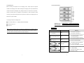
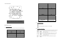
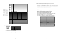
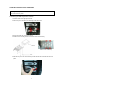
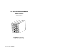
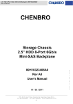
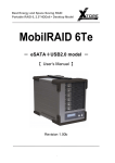
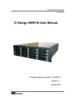
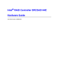
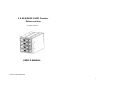
3-4 SAS/SATA II HDD Canister Deluxe version XC-34D1-SA1C-0-R USER’S MANUAL Document number: MAN-00078-B ii Preface Copyright Important Information Under the copyright laws, this publication may not be reproduced or transmitted in any form, Warranty electronic or mechanical, including photocopying, recording, storing in an information retrieval Our product is warranted against defects in materials and workmanship for a period of one system, or translating, in whole or in part, without the prior written consent of manufacturer year from the date of shipment, as evidenced by receipts or other documentation. Manufacturer, at its option, repair or replace equipment that proves to be defective during the Trademarks warranty period. This warranty includes parts and labor. Product and company names mentioned herein are trademarks or trade names of their The media on which you receive software are warranted not to fail to execute programming respective companies. instructions, due to defects in materials and workmanship, for a period of 90 days from date of shipment, as evidenced by receipts or other documentation. Manufacturer will, at its option, repair or replace software media that do not execute programming instructions if manufacturer receives notice of such defects during the warranty period. Manufacturer does not warrant that the operation of the software shall be uninterrupted or error free. National Instruments believes that the information in this document is accurate. The document Changes The Manufacturer reserves the right to revise this publication and to make changes in the content hereof without the obligation of The Manufacturer to notify any person of such revision or changes. has been carefully reviewed for technical accuracy. In the event that technical or typographical errors exist, manufacturer reserves the right to make changes to subsequent editions of this document without prior notice to holders of this edition. The reader should consult National Instruments if errors are suspected. In no event shall manufacturer be liable for any damages arising out of or related to this document or the information contained in it. EXCEPT AS SPECIFIED HEREIN, MANUFACTURER MAKES NO WARRANTIES, EXPRESS OR IMPLIED, AND SPECIFICALLY DISCLAIMS ANY WARRANTY OF MERCHANTABILITY OR FITNESS FOR A PARTICULAR PURPOSE. CUSTOMER’S RIGHT TO RECOVER DAMAGES CAUSED BY FAULT OR NEGLIGENCE ON THE PART OF MANUFACTURER SHALL BE LIMITED TO THE AMOUNT THERETOFORE PAID BY THE CUSTOMER. MANUFACTURER WILL NOT BE LIABLE FOR DAMAGES RESULTING FROM LOSS OF DATA, PROFITS, USE OF PRODUCTS, OR INCIDENTAL OR CONSEQUENTIAL DAMAGES, EVEN IF ADVISED OF THE POSSIBILITY THEREOF. This limitation of the liability of manufacturer will apply regardless of the form of action, whether in contract or tort, including negligence. Any action against manufacturer must be brought within one year after the cause of action accrues. Manufacturer shall not be liable for any delay in performance due to causes beyond its reasonable control. The warranty provided herein does not cover damages, defects, malfunctions, or service failures caused by owner’s failure to follow the manufacturer installation, operation, or maintenance instructions; owner’s modification of the product; owner’s abuse, misuse, or negligent acts; and power failure or surges, fire, flood, accident, actions of third parties, or other events outside reasonable control. iii iv Safety Precautions 9 The equipment has been dropped and/or damaged. Before getting started, please read the following important cautions: 9 The equipment has obvious signs of breakage. All cautions and warnings on the equipment or in the manuals should be noted. 9 Most electronic components are sensitive to electrical static discharge, therefore, be use liquid or detergent for cleaning. The use of a moisture sheet or cloth is sure to ground yourself at all times when installing the internal components. Use a recommended for cleaning. Please disconnect this equipment from the AC outlet before cleaning. Do not grounding wrist strap and place all electronic components in static-shielded devices. Grounding wrist straps can be purchased in any electronic supply store. Do not open the system’s top cover. If opening the cover for maintenance is a must, only a trained technician should do so. Integrated circuits on computer boards are sensitive to static electricity. Before handling a board or integrated circuit, touch an unpainted portion of the system unit chassis for a few seconds. This will help to discharge any static electricity on your body. Place this equipment on a reliable surface when install. A drop or fall could cause injury. Please keep this equipment from away humidity. Do not leave this equipment in an environment unconditioned, out of operation or storage temperature range may damage the equipment. Never pour any liquid into ventilation openings This could cause fire or electrical shock. Make sure the voltage of the power source is within the specification on the label when connecting the equipment to the power outlet. The current load and output power of loads shall be within the specification. This equipment must be connected to reliable grounding before using. Place the power cord out of the way of foot traffic. Do not place anything over the power cord. The power cord must be rated for the product, voltage and current marked on the product’s electrical ratings label. The voltage and current rating of the cord should be greater than the voltage and current rating marked on the product. If the equipment is not used for a long time, disconnect the equipment from mains to avoid being damaged by transient over-voltage. Never open the equipment. For safety reasons, only qualified service personnel should open the equipment. If one of the following situations arise, the equipment should be checked by service personnel: 9 The power cord or plug is damaged. 9 Liquid has penetrated the equipment. 9 The equipment has been exposed to moisture. 9 The equipment does not work well or will not work according to its user‘s manual. v vi Table of Contents CHAPTER 1 INTRODUCTION 1.1 Key features ¾ Support four 3.5” SAS and/or SATA II hard disk drives (HDD) on 3 ODD Bays space. ¾ Enclosure management controller chip on board ¾ SFF8448 compliance SGPIO interface Support through one SFF8087 mini SAS 4i Preface ............................................................................................................ iii Important Information ................................................................................ iii Safety Precautions .....................................................................................v connector CHAPTER 1 INTRODUCTION......................................................................... 1 ¾ Support direct HDD Activity/Fault LEDs signal input ¾ Support HDD Activity LEDs directly from SAS/SATA II HDD ¾ Support buzzer alarm 1.5 SGPIO and SES II Support ................................................................. 7 ¾ Support buzzer-mute button CHAPTER 2 INSTALLATION OVERVIEW ...................................................... 8 ¾ Support Power on, FAN fail, Over temperature LED indicator ¾ Support Fan Control automatic by temperature 1.1 Key features......................................................................................... 1 1.2 Unpacking list ...................................................................................... 2 1.3 Front Panel Features........................................................................... 3 1.4 Rear Panel Features ........................................................................... 4 2.1 Removing the HDD Tray from the enclosure ...................................... 8 vii 1 1.3 Front Panel Features 1.2 Unpacking list Before removing the subsystem from the shipping carton, visually inspect the physical condition of the shipping carton. Exterior damage to the shipping carton may indicate that the contents of the carton are damaged. If any damage is found, do not remove the components; contact the dealer where the subsystem was purchased for further instructions. Before continuing, first unpack the subsystem and verify that the contents of the shipping carton are all there and in good condition. The package contains the following items: ■ One set with HDD tray x 4 1.3.1 front view of 3 to 4 canister (Shipping without HDD installed) ■ Mounting screws x 16 n Buzzer mute o Power LED q Fan Fail LED r Drive tray p Over Temperature LED ■ Jumper x 2 LED indicators Note:Inspect the shipping cartons for evidence of physical damage. If a shipping carton appears damaged, request that the carrier’s agent be present when the carton is opened. LED NAME Keep all contents and packing material for the agent’s inspection. Power LED Color definition Behavior On:when system is powered on Blue Off:when system is powered off On:when system temperature exceeds Over Temperature LED Red threshold temperature Off:when system temperature is normal. On:when system detected fan abnormality Fan fail LED Red Off:when fan is normal operation HDD Activity/Ready : On:when HDD is inserted and detected. Flash:when accessing HDD Blue color Off:when there is no HDD or no detection. On:when HDD is detected as failure by host HDD Failure: Flash:RAID rebuilding Red color Off:when there is no HDD or normal (only supported on HBA) 2 3 1.4 Rear Panel Features Side band 6 A11 Rx 2+ A13 Rx 2- A14 Rx 3+ A16 Rx 3- A17 Tx 0+ B2 Tx 0- B3 Tx 1+ B5 Tx 1- B6 Sideband 7 B8 Sideband 3 B9 Sideband 4 B10 Sideband 5 B11 Tx 2+ B13 Tx 2- B14 Tx 3+ B16 Tx 3- B17 1.4.1 rear view of 3 to 4 canister A1,A4,A7,A12,A15,A18, SIGNAL GROUND n miniSAS host connector o Power input connectors N/C = not connected p Over-Temp Threshold ,Buzzer Setting and HDD Fail LED Input q Fan r Fan connector B1,B4,B7,B12,B15,B18 Power input connectors More details as below Four-pin standard power connectors for +12V/+5V/GND MiniSAS Host Connector A 36-pin Mini SAS connector is used for 4 SAS channels and sideband signals. HDD Activity / Fail LED Input Signal Connector Pins (1) For some HBAs supporting HDD Fail signal output: If used, this Rx 0+ A2 connector should be connected with HDD Fault signal from Rx 0- A3 HBA by external cable. Rx 1+ A5 Rx 1- A6 Sideband 0 A8 Sideband 1 A9 Sideband 2 A10 4 (2) For some HBAs supporting HDD Activity output: If used, this connector should be connected with HDD Activity signal from HBA external cable. (3) It’s left to open, as default, when HBA doesn’t support it. 5 1.5 SGPIO and SES II Support via Sideband Signals of 36-pin mini SAS Pin Status 1,2 3,4 5,6 7,8 Description Open Disable External Access LED input Close Enable External Access LED input Open Access LED from HDD Pin P11 Close Access LED from SGPIO The backplane is designed with one 36-pin mini SAS 4i connector which includes sideband input for LED control. See Table 3 for the pin assignment of the sideband inputs. The sideband on this product supports SGPIO (SFF8485). Open SGPIO Bit2 is HDD Fail, Bit3 is HDD ID ex. ARECA SGPIO Close SGPIO Bit2 is HDD ID, Bit3 is HDD Fail ex. LSI SGPIO currently supports the behavior of HDD Activity and Fault LEDs. The Open Disable SGPIO implementation of SGPIO is vender specific its SGPIO behavior. The HBA, RAID card, or Close Enable SGPIO M/B has to implement SGPIO following SFF8448 pin assignment. Please check with your HBA/RAID card/MB vendor for details. Pin Number Description Pin Number Please check with your AIC/Xtore contact window for the latest support of HBA. 1 GND 2 GND (Some HBAs do not support Activity LED even they use SGPIO) 3 HDD 0 Fail Input 4 HDD 0 Activity Input The pin assignment of the Sideband inputs follows SFF-8448 specifications. 5 HDD 1 Fail Input 6 HDD 1 Activity Input 7 HDD 2 Fail Input 8 HDD 2 Activity Input Signal SGPIO HDD 3 Activity Input Sideband 0 SClock 9 HDD 3 Fail Input 10 Pin Number Description Description Sideband 1 SLoad Sideband 2 Ground Ground 1.2 Mute Sideband 3 3.4 45℃ Sideband 4 SDataOut 5.6 50℃ Sideband 5 SDataIn Sideband 6 Controller Type Sideband 7 Backplane Type Fan Connectors JP1 is used to configure the type. Pin Number Description 1 GND 2 +12V 3 Tach ※ A 3-pin fan connector with failure detection ※ The canister also supports to be managed by IPMI interface 6 7 CHAPTER 2 INSTALLATION OVERVIEW Warning:Before you remove or install the unit, make sure the unit is not turned on or connected to the AC power. 2.1 Removing the HDD Tray from the enclosure 1. Press the latch to the right by the thumb. 2. Pull the tray door outward by the forefinger at the same time. 3. Remove the HDD tray from the enclosure 4. Install the four mounting screws to secure the drive in the disk tray. Bottom view of HDD tray 5. Slide the tray into a slot. Press the tray handle until the latch is closed and locks into place. 8