1
User Manual
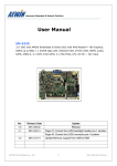
MB-8301
Mini-ITX with onboard Intel® 4th generation Core™ i7/i5/i3/Celeron Mobile
processor, Intel® QM87 chipset, DDR3 up to 16GB, 2 x Intel® Giga LAN,
HDMI, DVI, VGA & LVDS, 4 x SATA, 10 x USB, 6 x COM, GPIO, HD Audio,
PCI-Express X16 & X1 slots, 2 x Mini-PCIe, DC 8V ~ 32V input
Ver.
Release Date
1.0V
2013.11.19
AEWIN Technologies Co., Ltd
Update
Release
1
MB-8300 User Manual
Copyright
The content of this document and software with this product are copyrighted by
AEWIN technologies Co., Ltd,
This document contains proprietary information protected by copyright. All rights are
reserved; no part of this manual may be reproduced, copied, translated or transmitted
in any form or by any means without prior written permission of the manufacturer.
The content of this document is intended to be accurate and reliable; the original
manufacturer assumes no responsibility for any inaccuracies that may be contained in
this manual. The original manufacturer reserves the right to make improvements to the
products described in this manual at any time without prior notice
Trademark
All other product names mentioned herein are used for identification purpose only and
may be trademarks and/or registered trademarks of their respective companies
Limitation of liability
While reasonable efforts have been made to ensure the accuracy of this document,
the manufacturer and distributor assume no liability resulting from errors or omissions
in this document, or from the use of the information contained herein.
For more information or other AEWIN products, please visit our website
http://www.aewin.com.tw.
For technical supports, please send your inquiry to [email protected]
AEWIN Technologies Co., Ltd
2
MB-8300 User Manual
Packing list
Before use this product, please make sure that the following materials have been shipped.
1 x MB-8301 board
1 x SATA cable, L/ 200mm
( p/n: 46L-SATA11-00 )
1 x 12V/5V SATA power cable , L/ 150mm
( p/n: 46L-IPOW41-00 )
1 x CPU cooling Fan
( p/n: 49L-F00050-00 )
1 x CD Driver Utility
p/n: 46L-SATA11-00
p/n: 46L-IPOW41-00
p/n: 49L-F00050-00
Model Name
Description
MB-8301A-Q24
Mini-ITX w/ i7-4700EQ, 2 GLAN,HDMI/DVI/VGA/LVDS, COM, USB,
Mini-PCIe socket, 4 SATA, 8V ~ 32V DC input, PCIe X16 slot
MB-8301A-D27
Mini-ITX w/ i5-4400E , 2 GLAN,HDMI/DVI/VGA/LVDS, COM, USB,
Mini-PCIe socket, 4 SATA, 8V ~ 32V DC input, PCIe X16 slot
MB-8301A-D24
Mini-ITX w/ i3-4100E , 2 GLAN,HDMI/DVI/VGA/LVDS, COM, USB,
Mini-PCIe socket, 4 SATA, 8V ~ 32V DC input, PCIe X16 slot
MB-8301A-D22
Mini-ITX w/ Celeron 2000E , 2 GLAN,HDMI/DVI/VGA/LVDS, COM
Mini-PCIe socket, 4 SATA, 8V ~ 32V DC input, PCIe X16 slot
MB-8301B-Q24
Same as MB-830A-Q24, but come with, PCIe X16 & PCIe X1 slots
MB-8301B-D27
Same as MB-830A-D27, but come with, PCIe X16 & PCIe X1 slots
MB-8301B-D24
Same as MB-830A-D24, but come with, PCIe X16 & PCIe X1 slots
MB-8301B-D22
Same as MB-830A-D22, but come with, PCIe X16 & PCIe X1 slots
* If any of those items are missing or damaged, please contact with sales representative or distributor
AEWIN Technologies Co., Ltd
3
MB-8300 User Manual
Optional Accessory
Photo
Model Name
P/N:
RE-S01
PCIe riser card support 1 x PCIe X16 & 1 x PCI slots
Note: Work with MB-8301B Series only
P/N:
RE-S02
PCIe riser card support 2 x PCI slots
Note: Work with MB-8301B Series only
P/N:
RE-S03
PCIe riser card support 1 x PCIe X16 & 1 x PCIe X1 slots
Note: Work with MB-8301B Series only
P/N:
46L-ICOM38-00
Dual D-Sub 9-pin COM port card, L/ 250mm, with bracket
P/N:
46L-IUSB07-AA
Dual USB cable, L/ 250mm, with bracket
P/N:
46L-IPOW102-00
P4 4-pin to DC Jack lockable power cable, L/ 200mm
AEWIN Technologies Co., Ltd
4
MB-8300 User Manual
Safety Information
To prevent electrical shock hazard, disconnect the power cable from the electrical
outlet before relocating the system.
When adding or removing devices to or from the system, ensure that the power
cables for the devices are unplugged before the signal cables are connected. If
possible, disconnect all power cables from the existing system before you add a
device.
Before connecting or removing signal cables from the motherboard, ensure that all
power cables are unplugged.
Seek professional assistance before using an adapter or extension cord. These
devices could interrupt the grounding circuit.
Make sure that your power supply is set to the correct voltage in your area.
If you are not sure about the voltage of the electrical outlet you are using, contact
your local power company.
If the power supply is broken, do not try to fix it by yourself. Contact a qualified
service technician or your retailer.
Operation Safety
Before installing the motherboard and adding devices on it, carefully read all the
manuals that came with the package.
Before using the product, make sure all cables are correctly connected and the
power cables are not damaged. If you detect any damage, contact your dealer
immediately.
To avoid short circuits, keep paper clips, screws, and staples away from connectors,
slots, sockets and circuitry.
Avoid dust, humidity, and temperature extremes. Do not place the product in any
area where it may become wet.
Place the product on a stable surface.
If you encounter technical problems with the product, contact a qualified service
technician or your retailer.
AEWIN Technologies Co., Ltd
5
MB-8300 User Manual
Contents
Chapter
Chapter
1
General Information ……………………………………….5
1.1
Introduction …………………………………………..……………………...8
1.2
Specification …………………………………………………..………..…...9
1.3
Block Diagram …………………………………………….…….….............11
1.4
Board layout Dimension ……………………………………….……………..12
1.5
IO / Connector ………………………………………………………………….14
2
Hardware installation …………………………………….16
2.1
The location of onboard connectors ..………………..………………….16
2.2
The location of onboard jumpers ………………………………………...18
2.3
The function list of onboard jumpers setting ……………………………19
2.3.1
JP1 for Clean CMOS jumper ……………………………………….…...19
2.3.2
JP3 for Power AT/ATX mode selection …………………………..……20
2.3.3
JP4 for LVDS voltage select ………………………………………..……21
2.3.4
JP4 for LVDS brightness control mode..…………………………..……22
2.4
The pin define of onboard pin header ………………………….……......23
2.4.1
CN1 for Low Pin Count pin-header …………………………..…...........23
2.4.2
CN4 for 8-bit GPIO pin header ………..…….…………………..….......24
2.4.3
CN5 & CN6 for DC out for HDD power …………………………........25
2.4.4
CN7 & CN8 for USB2.0 pin-header ………………........……………..26
2.4.5
CN9 & CN10 for SATA 3.0/2.0 connector ………………………………27
2.4.6
CN11 for SPI programmer pin-heder ……………................................. 28
2.4.7
CN12 for PCI-Express X1 slot...............................................................29
2.4.8
CN14 for COM4, RS232 pin-header ......................................................30
2.4.9
CN16 for front panel pin-header .......................................... 31
2.4.10
CN19 for COM3, RS232 pin-header .......................................................32
2.4.11
CN21 for COM2, RS232/422/485 …………......................................... 33
2.4.12
CN22 for Half-size Mini-PCIe WLAN LED indictor ..................................35
2.4.13
CN23 for Full-size Mini-PCIe WLAN LED indictor................................... 36
2.4.14
CN25 for Full-size Mini-PCIe socket ......................................................37
AEWIN Technologies Co., Ltd
6
MB-8300 User Manual
Chapter
2.4.15
CN26 for Half-size Mini-PCIe sockets ......................................................38
2.4.16
CN27 for SIM holder ………......................................................................39
2.4.17
CN28 for Internal P4 4-pin power input connector ....................................40
2.4.18
CN29 for 4-channel Audio inputs …………….. .........................................41
2.4.19
CN30 for 4-channel Video inputs...............................................................42
2.4.20
CN39 for 24-bit dual channel LVDS connector …………...........................43
2.4.21
CN40 for LVDS backlight pin-header ........................................................45
2.4.22
CPU fan connector & System Fan connector ...........................................46
3
Programming WDT & GPIO ………………………..47
3.1
GPIO DOS sample code ............……………………..……………...…..…47
3.2
WatchDog timer DOS sample code .…………………… ..……….…..…...54
AEWIN Technologies Co., Ltd
7
MB-8300 User Manual
1.1 Introduction
MB-8301, a Mini-ITX board with onboard Intel® Haswell Mobile CPU with integrated Intel® QM87
Express chipset. Onboard display includes HDMI, DVI-D, VGA and 24-bit dual channel LVDS and two
DDR3 SO-DIMM supports a maximum of 16GB DDR3 1600 of system memory.
MB-8301 delivers flexible expansion slots allowing customers to install one PCI-Express X16 card and
two Mini-PCIe cards. It is built with a SIM card holder capable of installing a SIM card with a Full-size
Mini-PCIe 3G module for wireless connection. For half-size Mini-PCIe socket it also supports mSATA
SSD as storage device (Optional). Further more it comes with a PCI-Express X1 slot that can be paired
with AEWIN’s riser card for an additional 1 ~ 3 PCI slots for various application.
On the I/O ports, the MB-8301 provides plenty of connectivity. 1 x Intel® i211AT GbE LAN and 1 x
Intel® i217LM controller, 1 x RS232/422/485 & 5 x RS232, 4 x USB3.0 + 6 x USB2.0, HD Audio, PS/2
Keyboard/Mouse, 4 x SATA with RAID 0/1/5/10 and a LPC pin-header supporting AEWIN’s TPM
module for the added information protection. The MB-8301 accepts a wide range 8V ~ 32V DC input
suitable for a variety of applications in digital signage, industrial system, Military, POS, kiosks, and
factory automation.
About AEWIN
AEWIN offers reliable and solid products which are produced under Management System Standards:
ISO9001-2000 Certificate. The certificate keeps us focused on our quality objectives of management and
environmental production. Its willingness to customize standard products for meet unique customer
needs makes AEWIN different. All ODM projects are welcome. Years of experiences enables AEWIN to
fulfill the customer’s vision, by delivering products to exact specifications. AEWIN R&D team is proud of
its strong engineering background. R&D professionals account for 25% of the AEWIN workforce. We
focus on developing new products for both emerging and established markets
For more information about OEM/ODM, please contact us :
Email: [email protected]
AEWIN Technologies Co., Ltd
TEL: +886-2-8692-6677
8
MB-8300 User Manual
1.2 Specification of board
System
From Factor
Mini-ITX motherboard
CPU
Intel® Core™ i7-4700EQ, 2.4 GHz, Qual-Core / 6M L2, TDP 47W
( MB-8301A-Q24 )
Intel® Core™ i5-4400E,
2.7 GHz, Dual-Core / 3M L2, TDP 37W
( MB-8301A-D27 )
Intel® Core™ i3-4100E ,
2.4 GHz, Dual-Core / 3M L2, TDP 35W
( MB-8301A-D24 )
Chipset
Intel QM87 Express chipset
Memory
2 x 204-pin DDR3 1333/1600 MHz / SODIMM up to 16GB, w/o ECC support
BIOS
AMI SPI BIOS
SSD
Half-size Mini-PCIe socket support mSATA SSD
Watchdog timer
255 levels, 1 ~ 255 sec
Expansion
1 x PCI-Express X16 slot
1 x PCI-Express X1 ( work with riser card for PCIe X1 or PCI 32-bit/33 MHz expansion slots )
1 x Full-size Mini-PCIe socket w/ USB, PCIe signal
1 x Half-size Mini-PCIe socket w/ USB, PCIe or SATA signal
Board Size
170mm x 170mm
Operating Temp.
0°C~60°C (32°F~140°F)
Storage Temp.
.-20°C~80°C (-4°F~176°F)
Operating Hum.
10%~90% (non-condensing)
Display
Chipset
Intel® haswell processor integrated
Display interface
1 x external HDMI 1.4a
1 x external VGA
1 x external DVI-D
1 x internal 24-bit Dual Channel LVDS
I/O
Series Port
Internal : 1 x RS232/422/485 ( COM2 ), 4 x RS232
External : 1 x RS232
SATA
4 x SATA 6Gb/s, w/ RAID 0/1/5/10
USB
External : 4 x USB3.0 + 2 x USB2.0
Internal : 4 x USB2.0
Ethernet
1 x Intel® i211AT PCIe controller
AEWIN Technologies Co., Ltd
9
MB-8300 User Manual
1 x Intel® i217LM PHY support Intel® AMT 9.0
Audio
External : Line-in/out , Mic-in
Internal : Line-out , Mic-in
Digital I/O
8-bit GPIO interface
LPC
1 x LPC 2 x 10-pin header for Optional TPM module
Others
2 x cooling Fan header ( Smart fan support ) , 1 x PS/2 keyboard/Mouse
1 x Front Panel header for power on/off, reset, HDD/power LED indicator
1 x LVDS Backlight/inverter pin-header
Power
Power in
Wide range DC 8V ~ 32V input ( AT/ATX mode select by jumper )
Connector
1 x internal P4 4-pin power connector
Note : All specifications and photos are subject to change without notice
AEWIN Technologies Co., Ltd
10
MB-8300 User Manual
1.3 Block Diagram
Optional
Chip / IC
DDR
1 x DDR3 204-pin SO-DIMM
PCIe
PCI-Express X16 slot
th
4 Intel® Haswell Mobile
DDI
HDMI
DDR
Core™ i7/i5/i3
Level Shifter
1 x DDR3 204-pin SO-DIMM
eDP
DP to LVDS
DDI
DVI-D
X4 DMI
24-bit LVDS
X4 FDI
PCIe
VGA
& USB
VGA
Full-size Mini-PCIe
Intel® QM87
SATA / PCIe
Express Chipset
& USB
PCIe
Intel® I217LM GLAN
Half-size Mini-PCIe
PCIe
Intel® I211AT GLAN
LPC
F81866A Super I/O
USB
4 x USB3.0 + 6 x USB2.0
Watch Dog Timer
H/W Monitor
SATA
4 x SATA3
PS2 Keyboard / Mouse
8-bit GPIO
1 x RS232/422/485
PCIe
PCI-Express X1 slot
5 x RS232
HDA
ALC886-GR
SPI
BIOS
SMbus
1 x SMbus pin header
AEWIN Technologies Co., Ltd
11
MB-8300 User Manual
1.4 Board Layout Dimension
AEWIN Technologies Co., Ltd
12
MB-8300 User Manual
AEWIN Technologies Co., Ltd
13
MB-8300 User Manual
1.5 IO ports
GLAN + USB3.0
Audio
VGA + DVI-D
GLAN + USB3.0
PS2 Key/Mouse + USB2.0
COM + HDMI
Front audio
Half-size Mini-PCIe
DC 8V ~ 32V In
SIM card holder
PCI-Express X16
Full-size Mini-PCIe
RS232/422/485
Intel® Core i7/i5/i3
RS232
Processor
24-bit Dual-CH LVDS
Front Panel
RS232
CPU Fan connector
RS232
SPI Flash
Dual USB2.0
LPC
SATA3
GPIO
AEWIN Technologies Co., Ltd
Intel® QM87
SATA3
14
DDR3 SO-DIMM
MB-8300 User Manual
PS2 Key/Mouse
Dual USB2.0
RS232
HDMI
AEWIN Technologies Co., Ltd
VGA
DVI-D
GLAN
Dual USB3.0
15
GLAN
Audio
Dual USB3.0
PCIe X16 slot
MB-8300 User Manual
2.1 The location of onboard connectors
CN37
CN32
CN30
CN33
CN34
CN35
CN31
CN29
CN38
CN24
CN28
CN26
CN27
CN23
CN25
CN22
CN20
CN16
CN18
CN13
CN15
CN17
CPU Fan
CN19
CN14
CN12
Sys Fan
CN5
CN7
CN9
CN6
CN4
CN8
AEWIN Technologies Co., Ltd
CN1
CN10
CN3
CN2
CN11
16
MB-8300 User Manual
Label
Function
Label
Function
CN1
Low Pin Count
CN22
Half-size Mini-PCIe LED
CN2
SATA3
CN23
Full-size Mini-PCIe LED
CN3
SATA3
CN24
Full-size Mini-PCIe socket
CN4
SATA power
CN25
Half-size Mini-PCIe socket
CN5
SATA power
CN26
SIM card holder
CN6
GPIO
CN27
SMBUS pin header
CN7
USB 2.0 Pin header
CN28
P4 4-pin power input connector
CN8
USB 2.0 Pin header
CN29
RJ45 LAN + Dual USB 3.0
CN9
SATA3
CN30
RJ45 LAN + Dual USB 3.0
CN10
SATA3
CN31
PS2 keyboard/mouse + Dual USB 2.0
CN11
SPI Programmer
CN32
Audio jack
CN12
PCI-Express X1 slot
CN33
VGA connector
CN13
Power on/off, Reset, HDD/Power LED
CN34
COM1
CN14
LVDS backlight inverter
CN35
HDMI connector
CN15
COM4
CN36
N/C
CN16
COM3
CN37
DVI-D connector
CN17
COM5
CN38
Front Audio header
CN18
24-bit LVDS
CN39
N/C
CN19
COM6
CN40
N/C
CN20
COM2
CN41
N/C
CN21
PCI-Express X16 slot
CN42
N/C
AEWIN Technologies Co., Ltd
17
MB-8300 User Manual
2.2 The location of onboard jumpers
JP6
JP2
JP3
JP4
JP1
JP5
Label
Function
JP1
Panel Voltage ( VCC ) select
JP2
COM3 Pin-9 select mode ( RI/5V/12V )
JP3
COM4 Pin-9 select mode ( RI/5V/12V )
JP4
LVDS backlight control mode select
JP5
CMOS Clear jumper
JP6
AT/ATX power mode jumper select
AEWIN Technologies Co., Ltd
18
MB-8300 User Manual
2.3 The function list of onboard jumpers setting
-
2.3.1 : JP1 for Panel Voltage select
JP1
Closed Pin
Result
1-2 *
+3.3V
3-4
+5V
5-6
+12V
* Default setting
1
2
JP1
5
AEWIN Technologies Co., Ltd
6
19
MB-8300 User Manual
-
2.3.2: JP2 for COM3 box header Pin-8 function select
JP2
Closed Pin
Result
1-2 *
RI
3-4
+5V
5-6
+12V
* Default setting
5
1
JP2
6
AEWIN Technologies Co., Ltd
2
20
MB-8300 User Manual
-
2.3.3: JP3 for COM4 box header Pin-8 function select
JP3
Closed Pin
Result
1-2 *
RI
3-4
+5V
5-6
+12V
* Default setting
5
1
JP3
6
AEWIN Technologies Co., Ltd
2
21
MB-8300 User Manual
- 2.3.4 : JP4 for LVDS brightness control mode
JP4
Closed Pin
Result
1-2
PWM mode
2-3 *
DC Level
* Default setting
3
JP4
1
AEWIN Technologies Co., Ltd
22
MB-8300 User Manual
-
2.3.1 : JP5 for Clear CMOS
If you want to clean the CMOS data, set jumper to 2-3 just for few seconds, Then,
Move the jumper back to 1-2 pin
JP5
Closed Pin
Result
1-2 *
Normal
2-3
Clear CMOS
* Default setting
3
JP5
1
AEWIN Technologies Co., Ltd
23
MB-8300 User Manual
-
2.3.2: JP6 for ATX / AT mode
JP6
Closed Pin
Result
1-2 *
ATX mode
2-3
AT mode
* Default setting
3
JP6
1
AEWIN Technologies Co., Ltd
24
MB-8300 User Manual
2.4 The pin define of onboard pin header
- 2.4.1 : CN1 for Low Pin Count pin-header
CN1 : 2 x 7 header , pitch 2.0 mm
Pin
Signal
Pin
Signal
1
+3.3V
2
LAD0
3
LAD1
4
LAD2
5
LAD3
6
LFRAME
7
Reset
8
+5V
9
LCLK
10
LPME
11
GND
13
SERIRQ
Key
14
LDRQ
2
1
13
1
CN1
14
AEWIN Technologies Co., Ltd
2
25
MB-8300 User Manual
-
2.4.2 : CN4 & CN5 for 4-pin HDD power
CN4 : 4-pin wafer for SATA power connector
Pin
Signal
Pin
Signal
1
+12V
2
GND
3
GND
4
+5V
Note: Maximum output current 12V/1A, 5V/1A
CN5 : 4-pin wafer for SATA power connector
Pin
Signal
Pin
Signal
1
+12V
2
GND
3
GND
4
+5V
Note: Maximum output current 12V/1A, 5V/1A
4
CN4
1
4
1
CN5
AEWIN Technologies Co., Ltd
26
MB-8300 User Manual
2.4.3 : CN6 for 8-bit GPIO
CN6 : 2 x 6 header , pitch 2.0 mm
Pin
Signal
Pin
Signal
1
+3.3V
2
GPIO0
3
GPIO1
4
GPIO2
5
GPIO3
6
GPIO4
7
GPIO5
8
GPIO6
9
GPIO7
10
Key
11
+5V
12
GND
2
12
11
1
CN6
2
AEWIN Technologies Co., Ltd
1
27
MB-8300 User Manual
-
2.4.4 : CN7 & CN8 for USB 6/7 , USB 8/9
CN7: 2 x 5 header , pitch 2.54 mm
Pin
Signal
Pin
Signal
1
+5V
2
+5V
3
USB6_ data-
4
USB7_data-
5
USB6_ data+
6
USB7_data+
7
GND
8
GND
9
Key
10
GND
CN8: 2 x 5 header , pitch 2.54 mm
Pin
Signal
Pin
Signal
1
+5V
2
+5V
3
USB8_ data-
4
USB9_data-
5
USB8_ data+
6
USB9_data+
7
GND
8
GND
9
Key
10
GND
10
9
CN7
2
1
10
9
CN8
2
1
AEWIN Technologies Co., Ltd
28
MB-8300 User Manual
-
2.4.5 : CN11 for SPI programmer
CN11 : 2 x 4 header , pitch 2.54 mm
Pin
Signal
Pin
Signal
1
+3.3V
2
GND
3
CS_N ( Chip Select )
4
SCLK ( Serial Clock)
5
MISO ( Master Input, Slave Output )
6
MOSI ( Master Output, Slave Input )
7
N/C
8
FLASH_IO
7
1
CN11
8
2
AEWIN Technologies Co., Ltd
29
MB-8300 User Manual
-
2.4.6 : CN12 for PCI-Express X1 slot
Note: This slot could work with AEWIN’s RE-S0X riser card to get PCIe X16 & PCI expansion slots
Regarding the PCIe X16 slot, The Max. power that could support is 35W PCIe add-on card
Pin
Side B
Side A
1
+12V
PRSNT1
2
+12V
+12V
3
+12V
+12V
4
GND
GND
5
SMCLK
TCK
6
SMDAT
TDI
7
GND
TOD
8
+3.3V
TMS
9
RST
+3.3V
10
+3.3V AUX
+3.3V
11
WAKE
PWRGD
Key Notch
12
Reserved
GND
13
GND
REFCLK+
14
HSOp
REFCLK-
15
HSOn
GND
16
GND
HSIp
17
PRSNT2
HSIn
18
GND
GND
AEWIN Technologies Co., Ltd
Configuration of MB-8300C with RE-S01 riser card
30
MB-8300 User Manual
-
2.4.7 : CN13 for Front panel
CN13 : 2 x 4 header , pitch 2.54 mm
Pin
Signal
Pin
Signal
1
HDD_LED+
2
Power_LED+
3
HDD_LED-
4
GND
5
GND
6
GND
7
RESET+
8
Power Switch
8
CN13
AEWIN Technologies Co., Ltd
31
2
7
1
MB-8300 User Manual
-
2.4.8 : CN14 for LVDS Backlight pin header
CN14: 1 x 5 wafer , Pitch : Pitch 2.0 mm
Pin
Signal
Pin
Signal
1
+12V
2
GND
3
Backlight Enable
4
Backlight Control
5
+5V
5
CN14
1
AEWIN Technologies Co., Ltd
32
MB-8300 User Manual
-
2.4.9 : CN15 for COM4 box header
CN15 : 2 x 5 header, pitch 2.00 mm
Pin
Signal
Pin
Signal
1
DCD, Data carrier detect
2
DSR, Data set ready
3
RXD, Receive Data
4
RTS, Request to send
5
TXD, Send Data
6
CTS, Clear to se
7
DTR, Data Terminal Ready
8
RI, Ring indicator
9
GND
10
N/C
2
10
CN15
1
9
AEWIN Technologies Co., Ltd
33
MB-8300 User Manual
-
2.4.10 : CN16 for COM3 box header
CN16 : 2 x 5 header, pitch 2.00 mm
Pin
Signal
Pin
Signal
1
DCD, Data carrier detect
2
DSR, Data set ready
3
RXD, Receive Data
4
RTS, Request to send
5
TXD, Send Data
6
CTS, Clear to se
7
DTR, Data Terminal Ready
8
RI, Ring indicator
9
GND
10
N/C
2
10
1
9
AEWIN Technologies Co., Ltd
CN16
34
MB-8300 User Manual
-
2.4.11 : CN17 for COM5 box header
CN17 : 2 x 5 header, pitch 2.00 mm
Pin
Signal
Pin
Signal
1
DCD, Data carrier detect
2
DSR, Data set ready
3
RXD, Receive Data
4
RTS, Request to send
5
TXD, Send Data
6
CTS, Clear to se
7
DTR, Data Terminal Ready
8
RI, Ring indicator
9
GND
10
N/C
2
10
CN17
1
9
AEWIN Technologies Co., Ltd
35
MB-8300 User Manual
-
2.4.12 : CN18 for 24-bit Dual Channel LVDS
CN18 : connector type : DF13A-40DP-1.25V
Pin
Signal
Pin
Signal
Pin
Signal
1
LVDS_VCC
15
LVDSA_1+
29
GND
2
LVDS_VCC
16
LVDSB_1+
30
GND
3
LVDS_VCC
17
GND
31
DDC_Clock
4
LVDS_VCC
18
GND
32
DDC_Data
5
GND
19
LVDSA_2-
33
GND
6
GND
20
LVDSB_2-
34
GND
7
LVDSA_0-
21
LVDSA_2+
35
LVDSA_3-
8
LVDSB_0-
22
LVDSB_2+
36
LVDSB_3-
9
LVDSA_0+
23
GND
37
LVDSA_3+
10
LVDSB_0+
24
GND
38
LVDSB_3+
11
GND
25
LVDSA_Clock-
39
SMB_Clock
12
GND
26
LVDSB_Clock-
40
SMB_Data
13
LVDSA_1-
27
LVDSA_Clock+
14
LVDSB_1-
28
LVDSB_Clock+
39
40
CN18
1
2
AEWIN Technologies Co., Ltd
36
MB-8300 User Manual
-
2.4.13 : CN19 for COM6 box header
CN19 : 2 x 5 header, pitch 2.00 mm
Pin
Signal
Pin
Signal
1
DCD, Data carrier detect
2
DSR, Data set ready
3
RXD, Receive Data
4
RTS, Request to send
5
TXD, Send Data
6
CTS, Clear to se
7
DTR, Data Terminal Ready
8
RI, Ring indicator
9
GND
10
N/C
2
10
1
9
AEWIN Technologies Co., Ltd
CN19
37
MB-8300 User Manual
-
2.4.14 : CN20 for COM2 , RS232/422/485
Note: COM2 RS-232/422/485 can be set by BIOS setting. Default is RS-232.
CN20 : 2 x 5 header , Pitch 2.00 mm
Pin
RS232 mode
RS422 mode
RS485 mode
1
DCD, Data carrier detect
TXD-
TXD-
2
DSR, Data set ready
3
RXD, Received Data
TXD+
TXD+
4
RTS, Request to send
5
TXD, Transmitted Data
6
CTS, Clear to sent
7
DTR, Data terminal ready
8
RI, Ring indicator
9
GND
10
N/C
2
RXD+
RXD-
10
CN20
1
9
AEWIN Technologies Co., Ltd
38
MB-8300 User Manual
-
2.4.15 : CN22 for Half-size Mini-PCIe WLAN LED indictor
CN22 : 1 x 2 , 2-pin wafer
Pin
Signal
Pin
Signal
1
LED_WLAN
2
+3.3V
Note: Half-size Mini-PCIe card could support USB , SATA or PCIe signal.
You can select different mode in the BIOS . The default setting is PCIE signal.
1
AEWIN Technologies Co., Ltd
2
CN22
39
MB-8300 User Manual
-
2.4.16 : CN23 for Full-size Mini-PCIe WLAN LED indictor
CN23 : 1 x 2 , 2-pin wafer
Pin
Signal
Pin
Signal
1
LED_WLAN
2
+3.3V
1
2
CN23
AEWIN Technologies Co., Ltd
40
MB-8300 User Manual
- 2.4.17 : CN24 for Full-size Mini-PCIe socket
Pin
Signal
Pin
Signal
1
WAKE
27
GND
2
+3.3V AUX
28
+1.5V
3
N/C
29
GND
4
GND
30
SMBCLK
5
N/C
31
PETN0
6
+1.5V
32
SMBDATA
7
CLKREQ
33
PETP0
8
UIM_PWR
34
GND
9
GND
35
GND
10
UIM_DATA
36
USB_D-
11
REFCLK-
37
GND
12
UIM_CLK
38
USB_D+
13
REFCLK+
39
+3.3V AUX
14
UIM_RESET
40
GND
15
GND
41
+3.3V AUX
16
UIM_VPP
42
LED_WWAN
17
UIM_C8
43
GND
18
GND
44
LED_WLAN
19
UIM_C4
45
N/C
20
W_Disable
46
N/C
21
GND
47
N/C
22
PERST
48
+1.5V
23
PERN0
49
N/C
24
+3.3V AUX
50
GND
25
PERP0
51
N/C
26
GND
52
+3.3V AUX
AEWIN Technologies Co., Ltd
CN24
41
MB-8300 User Manual
-
2.4.18 : CN25 for Half-size Mini-PCIe socket.
Note: Half-size Mini-PCIe card could support SATA or PCIe signal. The default setting is PCIE signal.
You can select different mode in the BIOS
Pin
Signal
Pin
Signal
1
WAKE
27
GND
2
+3.3V AUX
28
+1.5V
3
Reserved
29
GND
4
GND
30
SMBCLK
5
Reserved
31
PETN0
6
+1.5V
32
SMBDATA
7
CLKREQ
33
PETP0
8
Reserved
34
GND
9
GND
35
GND
10
UIM_DATA
36
USB_D-
11
REFCLK-
37
Reserved
12
Reserved
38
USB_D+
13
REFCLK+
39
Reserved
14
Reserved
40
GND
15
GND
41
Reserved
16
Reserved
42
LED_WWAN
17
Reserved
43
Reserved
18
GND
44
LED_WLAN
19
Reserved
45
Reserved
20
Reserved
46
N/C
21
GND
47
Reserved
22
PERST
48
+1.5V
23
PERN0
49
Reserved
24
+3.3V AUX
50
GND
25
PERP0
51
Reserved
26
GND
52
+3.3V
AEWIN Technologies Co., Ltd
CN25
42
MB-8300 User Manual
-
2.4.19 : CN26 for SIM holder
CN26 : SIM card holder
Pin
Signal
Pin
Signal
C1
VCC
C2
RESET
C3
CLOCK
C4
Reserved
C5
GND
C6
VPP
C7
I/O
C8
Reserved
C1
C4
CN26
C5
C8
AEWIN Technologies Co., Ltd
43
MB-8300 User Manual
-
2.4.16 : CN27 for SMBUS pin header
CN27 : 1 x 5 pin header , 2.00 mm pitch
Pin
Signal
Pin
Signal
1
+5V
2
Clock
3
Data
4
N/C
5
GND
CN27
1
AEWIN Technologies Co., Ltd
44
5
MB-8300 User Manual
-
2.4.17 : CN28 for internal 4-pin power input
CN28 : ATX 2 x 2
Pin
Signal
Pin
Signal
1
GND
2
GND
3
8V ~ 32V DC input
4
8V ~ 32V DC input
3
1
4
2
CN28
AEWIN Technologies Co., Ltd
45
MB-8300 User Manual
-
2.4.13 : CN38 for front panel Audio pin header
CN38 : 2 x 5 header, pitch 2.00 mm
Pin
Signal
Pin
Signal
1
Mic-In_L
2
GND
3
Mic-In_R
4
N/C
5
Line-Out_R
6
Mic-In_JD
7
GND
8
N/C
9
Line-Out_L
10
Line-Out_JD
10
9
CN38
2
1
AEWIN Technologies Co., Ltd
46
MB-8300 User Manual
3. BIOS setting Menu
-
3.1 Main Menu
The Main Menu of BIOS Setup Utility provide a quick overview of basic system information and the
ability to change the system Date, time ……………..
AEWIN Technologies Co., Ltd
47
MB-8300 User Manual
-
3.2 Advanced Menu
The Advanced Menu of BIOS Setup Utility allows users to configure advanced system settings.
AEWIN Technologies Co., Ltd
48
MB-8300 User Manual
-
3.2.1 Advanced Menu
PCI Express Setting:
Description: This item manually sets the maximum read request size of the PCI Express device or
allows the system BIOS to choose the value (Auto). The options are Auto, 128 Bytes, 256 Bytes,
512 Bytes, 1024 Bytes, 2048 Bytes and 4096 Bytes.
AEWIN Technologies Co., Ltd
49
MB-8300 User Manual
-
3.2.2 Advanced Menu
ACPI Setting:
Enable ACPI Auto Configuration
< Disable >
Description : Use this feature to configure Advanced Configuration and Power Interface (ACPI)
power management settings for your system.
AEWIN Technologies Co., Ltd
50
MB-8300 User Manual
-
3.2.3 Advanced Menu
Trusted Computing:
Security Device Support
< Disable >
Description : Select Enabled to activate support for trusted platforms (TPM 1.1/1.2) and allow the
BIOS to automatically download the drivers needed to provide support for the platforms specified.
The options are Disable and Enable.
AEWIN Technologies Co., Ltd
51
MB-8300 User Manual
-
3.2.4 Advanced Menu
CPU Configuration:
This item displays the current CPU Revision, Current CPU1 Memory Frequency, Memory Type and
Memory Reference Code Revision.
Hyper-threading :
lntel® Hyper Threading Technology (Available when supported by the OS and the CPU). Select
Enabled to enable Hyper_Threading support to increase CPU performance. The options are Enabled
and Disabled.
Active Processor Cores :
Set to Enabled to use a processor's Second Core and beyond. (Please refer to Intel's web site for
more information.) The options are All, l, 2 and 3.
AEWIN Technologies Co., Ltd
52
MB-8300 User Manual
-
3.2.5 Advanced Menu
SATA Configuration:
When this submenu is selected, the AMI BIOS automatically detects the presence of the IDE
Devices and displays the following items:
SATA Mode Selection :
This item selects the mode for the installed drives. The options are Disabled, IDE Mode, AHCI Mode
and RAID Mode.
AEWIN Technologies Co., Ltd
53
MB-8300 User Manual
-
3.2.6 Advanced Menu
Intel® Rapid Start Technology:
< Disabled >
Description : Intel® Rapid Start Technology enables your system to get up and running faster from
even the deepest sleep, saving time and power consumption.
AEWIN Technologies Co., Ltd
54
MB-8300 User Manual
-
3.2.6 Advanced Menu
Intel® AMT:
< Enabled >
Description : This option enables Intel AMT support. The options are Enabled and Disabled..
AEWIN Technologies Co., Ltd
55
MB-8300 User Manual
-
3.2.6 Advanced Menu
USB Configuration:
This feature enables support for USB function parameters The options are Enabled, and Disabled.
Legacy USB Support:
This feature enables support for legacy USB devices. Select Auto to disable legacy support if USB
devices are not present. Select Disable to have USB devices available only for EFl applications. The
options are Enabled, Disabled and Auto.
AEWIN Technologies Co., Ltd
56
MB-8300 User Manual
-
3.2.6 Advanced Menu
SATA PCIE select:
Select Half-size Mini-PCIe socket to support SATA signal or PCIe signal.
Default is support STAT signal
COM2 port mode:
Select COM2 port to support RS232 , RS-422 or RS485 mode.
Default is RS232 mode
Watch Dog Function:
Allows AMT to reset or power down the system if the operating system or BIOS hangs or crashes.
The options are Disabled, and Enabled.
AEWIN Technologies Co., Ltd
57
MB-8300 User Manual
-
3.2.6 Advanced Menu
F81866 Super IO Configuration:
Description : Select Enabled to enable the onboard serial port. The options are Enabled and
Disabled.
AEWIN Technologies Co., Ltd
58
MB-8300 User Manual
-
3.2.7 Advanced Menu
F81866 H/W monitor:
Smart Fan Mode Configuration
< Enabled/Disabled >
Description : This feature allows the user to check CPU temperature and the fan speed. And also
displays the current voltages of the above voltage monitors
AEWIN Technologies Co., Ltd
59
MB-8300 User Manual
-
3.2.8 Advanced Menu
Smart Fan Mode Configuration
This feature allows the user to decide how the system controls the speeds of the onboard fans. The
CPU temperature and the fan speed are correlative. When the CPU on-die temperature increases,
the fan speed will also increase for effective system cooling. Select "Full Speed" to allow the
onboard fans to run at full speed (of 100% Pulse Width Modulation Duty Cycle) for maximum
cooling.
AEWIN Technologies Co., Ltd
60
MB-8300 User Manual
-
3.2.10 Advanced Menu
Serial Port Console Redirection
Console Redirection
< Disabled >
Description : This feature allows the user to remotely access the entire boot sequence via a serial
console
Default setting is Disabled
AEWIN Technologies Co., Ltd
61
MB-8300 User Manual
-
3.3 Chipset Menu
Serial Port Console Redirection
Console Redirection
< Disabled >
Description : This feature allows the user to remotely access the entire boot sequence via a serial
console
Default setting is Disabled
AEWIN Technologies Co., Ltd
62
MB-8300 User Manual
-
3.3.1 Chipset Menu
PCH LAN Controller :
Select Enabled to enable the onboard gigabit Ethernet controller. The settings are Enabled and
Disabled
Wake on LAN :
Select Enabled to enable the capability to ‘wake-up’ the system from the S5~power state (Soft Off
State) through the Ethernet controller. The settings are Enabled and Disabled.
Restore AC Power Loss :
Use this feature to set the power state after a power outage. Select Power-Off for the system power
to remain off after a power loss. Select Power-On for the system power to be turned on after a
power loss. Select Last State to allow the system to resume its’ last power state before a power
lost. The options are Power-On, Power-Off and Last State.
AEWIN Technologies Co., Ltd
63
MB-8300 User Manual
-
3.3.2 Chipset Menu
PCI Express Configuration:
Description: Use this feature to enable or disable PCIe slot Option ROMs. The options are Disabled
and Enabled.
AEWIN Technologies Co., Ltd
64
MB-8300 User Manual
-
3.3.3 Chipset Menu
PCH Azalia Configuration:
Description: Select Enabled to enable the Azalia High Definition Audio feature. The settings are
Enabled and Disabled.
AEWIN Technologies Co., Ltd
65
MB-8300 User Manual
-
3.3.4 Chipset Menu
VT-d Capability: (Available when supported by the CPU)
VT-d
< Disabled/enabled >
Description: Select Enabled to enable Intel's \/irtualization Technology support for Direct l/O VT-d
by reporting the I/O device assignments to VMM through the DMAR ACPI Tables. This feature offers
fully-protected I/O resource sharing across the lntel platforms, providing the user with greater
reliability, security and availability in networking and data-sharing. The settings are Enabled and
Disabled.
AEWIN Technologies Co., Ltd
66
MB-8300 User Manual
-
3.3.6 Chipset Menu
Graphics Configuration:
Description: Select primary video device that BIOS will use to for output
Default setting is <Auto>
IGT : Integrated Graphics Device.
PEG : PCI Express Graphics
AEWIN Technologies Co., Ltd
67
MB-8300 User Manual
-
3.3.7 Chipset Menu
PCH-IO Configuration:
LCD Control
Description: This feature allows the user to select different LVDS Panel mode , resolution and
backlight control
AEWIN Technologies Co., Ltd
68
MB-8300 User Manual
-
3.3.7 Chipset Menu
Memory Information
This item displays the current Memory Frequency, Memory Type and Memory Reference Code
Revision.
Memory Frequency:
Description: This feature allows the user to select the memory speed. Under normal conditions,
please set this to Auto.
AEWIN Technologies Co., Ltd
69
MB-8300 User Manual
-
3.4 Boot Menu
Boot Configuration:
This feature allows the user to specify which devices are boot devices and the order of priority from
which the systems boots from during startup.
Fast Boot:
This feature allows booting with initialization with a minimal set of devices required to launch an
active boot option. The options are Disabled, and Enabled.
AEWIN Technologies Co., Ltd
70
MB-8300 User Manual
-
3.5 Security Menu
Password Description:
Description:
Administrator Password : Press Enter to create a new, or change an existing Administrator
password.
User Password : Press Enter to create a new, or change an existing User password.
AEWIN Technologies Co., Ltd
71
MB-8300 User Manual
-
3.6 Save & Exit Menu
Description:
Save Change and Reset : When you have completed the system configuration changes, select this
option to leave the BIOS Setup Utility and reboot the computer, so the new system configuration
parameters can take effect. Select Save Changes and Exit from the Exit menu and press <Enter>
Discard Changes and Reset : Select this option to quit the BIOS Setup without making any
permanent changes to the system configuration, and reboot the computer. Select Discard Changes
and Exit from the Exit menu and press <Enter>.
Restored Defaults : To set this feature, select Restore Defaults from the Exit menu and press
<Enter>. These are factory settings designed for maximum system stability, but not for maximum
performance.
AEWIN Technologies Co., Ltd
72
MB-8300 User Manual
4.1 GPIO Sample Program for DOS environment
//AEWIN GPIO Program for MB-8301(DOS Version)
#include <stdio.h>
#include <dos.h>
#include <inlines/pc.h>
#define index_port 0x2E
#define data_port 0x2F
//Super IO Index Port Address
//Super IO Data Port Address
void Enter_sio_config();
void Exit_sio_config();
void help();
int main(int argc, char *argv[])
{
int val, GPIO_SEL;
if (argc!=2){
help();
return;
}
Enter_sio_config();
if(strcmp(argv[1], "-r") == 0){
printf("Read GP80~GP83\n");
outportb(index_port, 0x8A);
val = inportb(data_port);
if ((val&0x01) == 0x00)
printf("GPI80 -> Low\n");
else
printf("GPI80 -> High\n");
if ((val&0x02) == 0x00)
printf("GPI81 -> Low\n");
AEWIN Technologies Co., Ltd
73
MB-8300 User Manual
else
printf("GPI81 -> High\n");
if ((val&0x04) == 0x00)
printf("GPI82 -> Low\n");
else
printf("GPI82 -> High\n");
if ((val&0x08) == 0x00)
printf("GPI83 -> Low\n");
else
printf("GPI83 -> High\n");
}
else if(strcmp(argv[1], "-84h") == 0){
printf("(GPO84 High >> 3.3v)\n");
GPIO_SEL = 0x10;
outportb(index_port, 0x89);
val = inportb(data_port)|GPIO_SEL;
outportb(data_port, val);
}
else if(strcmp(argv[1], "-84l") == 0){
printf("(GPO84 Low >> 0.0v)\n");
GPIO_SEL = 0x10;
outportb(index_port, 0x89);
val = inportb(data_port)&(~GPIO_SEL);
outportb(data_port, val);
}
else if(strcmp(argv[1], "-85h") == 0){
printf("(GPO85 High >> 3.3v)\n");
GPIO_SEL = 0x20;
outportb(index_port, 0x89);
val = inportb(data_port)|GPIO_SEL;
outportb(data_port, val);
}
else if(strcmp(argv[1], "-85l") == 0){
printf("(GPO85 Low >> 0.0v)\n");
AEWIN Technologies Co., Ltd
74
MB-8300 User Manual
GPIO_SEL = 0x20;
outportb(index_port, 0x89);
val = inportb(data_port)&(~GPIO_SEL);
outportb(data_port, val);
}
else if(strcmp(argv[1], "-86h") == 0){
printf("(GPO86 High >> 3.3v)\n");
GPIO_SEL = 0x40;
outportb(index_port, 0x89);
val = inportb(data_port)|GPIO_SEL;
outportb(data_port, val);
}
else if(strcmp(argv[1], "-86l") == 0){
printf("(GPO86 Low >> 0.0v)\n");
GPIO_SEL = 0x40;
outportb(index_port, 0x89);
val = inportb(data_port)&(~GPIO_SEL);
outportb(data_port, val);
}
else if(strcmp(argv[1], "-87h") == 0){
printf("(GPO87 High >> 3.3v)\n");
GPIO_SEL = 0x80;
outportb(index_port, 0x89);
val = inportb(data_port)|GPIO_SEL;
outportb(data_port, val);
}
else if(strcmp(argv[1], "-87l") == 0){
printf("(GPO87 Low >> 0.0v)\n");
GPIO_SEL = 0x80;
outportb(index_port, 0x89);
val = inportb(data_port)&(~GPIO_SEL);
outportb(data_port, val);
}
else{
help();
}
AEWIN Technologies Co., Ltd
75
MB-8300 User Manual
Exit_sio_config();
return;
}
void help()
{
printf("AEWIN GPI Program\n");
printf("Usage:\n");
printf("GPIO -r (Read F81866 GP80~GP83)\n");
printf("GPIO -xh (x=84~87, and set GPx to high)\n");
printf("GPIO -xl (x=84~87, and set GPx to low )\n");
printf("ex:
printf("GPIO -84h (Set GP84 to high)\n");
\n");
}
void Enter_sio_config()
{
outportb(index_port, 0x87);
delay(1);
//delay some time
outportb(index_port, 0x87);
outportb(index_port, 0x07);
outportb(data_port, 0x06);
}
void Exit_sio_config()
{
outportb(index_port, 0xAA);
}
AEWIN Technologies Co., Ltd
76
MB-8300 User Manual
4.2 Watchdog timer Sample Program for DOS environment
//AEWIN Watch dog program for MB-8301(Dos Version)
#include <stdio.h>
#include <string.h>
#include <dos.h>
#include <stdlib.h>
#include <inlines/pc.h>
#define index_port 0x2E
//Super IO Index port address
#define data_port 0x2F
//Super IO Data port address
void Enter_sio_config();
void Exit_sio_config();
void help();
int main(int argc, char *argv[])
{
int data_rw8, time;
if (argc<2){
help();
return;
}
if(strcmp(argv[1], "-s") == 0){
//Show Watchdog Register Settings
Enter_sio_config();
outportb(index_port, 0xF5);
data_rw8 = inportb(data_port)&0x08;
if(data_rw8 == 0x00){
//second mode
outportb(index_port, 0xF6);
data_rw8 = inportb(data_port);
printf("Second mode: %d second\n", data_rw8);
}
AEWIN Technologies Co., Ltd
77
MB-8300 User Manual
else{
//minute mode
outportb(index_port, 0xF6);
data_rw8 = inportb(data_port);
printf("Minute mode: %d minute\n", data_rw8);
}
}
else if(strcmp(argv[1], "-t") ==0 ){
//Set Time-out Value
if(argv[2] == NULL){
help();
return;
}
else{
Enter_sio_config();
outportb(index_port, 0xF6);
outportb(data_port , 0x00);
//Clear Status
outportb(index_port, 0xF5);
data_rw8 = 0x32;
outportb(data_port, data_rw8);
sscanf(argv[2], "%d", &time);
outportb(index_port, 0xF6);
outportb(data_port, time);
if(time==0){
//Disable count
outportb(index_port, 0xF5);
data_rw8 = inportb(data_port)&0xCF;
outportb(data_port , data_rw8);
}
else{
outportb(index_port, 0xFA);
outportb(data_port , 0x01);
//Enable reset function
}
printf("Watchdog Timer will count down for %d second(s)\n", time);
}
}
else if(strcmp(argv[1], "-m") ==0 ){
AEWIN Technologies Co., Ltd
78
MB-8300 User Manual
//Set Time-out Value
if(argv[2] == NULL){
help();
return;
}
else{
Enter_sio_config();
outportb(index_port, 0xF6);
outportb(data_port , 0x00);
outportb(index_port, 0xF5);
data_rw8 = 0x32;
//Clear Status
data_rw8 |= 0x08;
outportb(data_port, data_rw8);
sscanf(argv[2], "%d", &time);
outportb(index_port, 0xF6);
outportb(data_port, time);
if(time==0){
//Disable count
outportb(index_port, 0xF5);
data_rw8 = inportb(data_port)&0xCF;
outportb(data_port , data_rw8);
}
else{
outportb(index_port, 0xFA);
outportb(data_port , 0x01);
//Enable reset function
}
printf("Watchdog Timer will count down for %d minute(s)\n", time);
}
}
Exit_sio_config();
return;
}
void Enter_sio_config()
//Enter W83627EHF Configuration
{
outportb(index_port, 0x87);
delay(1);
AEWIN Technologies Co., Ltd
//Delay some time
79
MB-8300 User Manual
outportb(index_port, 0x87);
outportb(index_port, 0x07);
outportb(data_port , 0x07);
//Super IO Selct Bank Register Number
//Select logical device 7
}
void Exit_sio_config()
{
//Exit W83627EHF Configuration
outportb(index_port, 0xAA);
}
void help()
{
printf("AEWIN Watchdog Timer Program\n");
printf("Usage: WDT -s
(Show Watchdog Register Settings)\n");
printf("Usage: WDT -t xxx (Set Time-out Value)\n");
printf("
xxx = 1 ~ 255 seconds\n");
printf("
xxx = 0 : Time-out Disable \n");
printf("Usage: WDT -m xxx (Set Time-out Value)\n");
printf("
xxx = 1 ~ 255 minutes\n");
printf("
xxx = 0 : Time-out Disable \n");
}
AEWIN Technologies Co., Ltd
80
MB-8300 User Manual
Device Resources
AEWIN Technologies Co., Ltd
81
MB-8300 User Manual